EP1536137A1 - Kraftstoffpumpe für eine Brennkraftmaschine - Google Patents
Kraftstoffpumpe für eine Brennkraftmaschine Download PDFInfo
- Publication number
- EP1536137A1 EP1536137A1 EP04105725A EP04105725A EP1536137A1 EP 1536137 A1 EP1536137 A1 EP 1536137A1 EP 04105725 A EP04105725 A EP 04105725A EP 04105725 A EP04105725 A EP 04105725A EP 1536137 A1 EP1536137 A1 EP 1536137A1
- Authority
- EP
- European Patent Office
- Prior art keywords
- chamber
- fuel pump
- piston
- diaphragm
- oil
- Prior art date
- Legal status (The legal status is an assumption and is not a legal conclusion. Google has not performed a legal analysis and makes no representation as to the accuracy of the status listed.)
- Granted
Links
- 239000000446 fuel Substances 0.000 title claims abstract description 28
- 238000002485 combustion reaction Methods 0.000 title claims abstract description 7
- 238000005086 pumping Methods 0.000 claims abstract description 8
- 230000033228 biological regulation Effects 0.000 claims description 4
- 230000007423 decrease Effects 0.000 claims description 2
- 229910000831 Steel Inorganic materials 0.000 claims 1
- 239000010959 steel Substances 0.000 claims 1
- 238000000926 separation method Methods 0.000 abstract 1
- 238000006073 displacement reaction Methods 0.000 description 3
- 239000012530 fluid Substances 0.000 description 3
- 238000002347 injection Methods 0.000 description 3
- 239000007924 injection Substances 0.000 description 3
- 239000000356 contaminant Substances 0.000 description 2
- 239000002245 particle Substances 0.000 description 2
- 230000002093 peripheral effect Effects 0.000 description 2
- 238000004891 communication Methods 0.000 description 1
- 230000003247 decreasing effect Effects 0.000 description 1
- 230000007812 deficiency Effects 0.000 description 1
- 239000013013 elastic material Substances 0.000 description 1
- 238000011156 evaluation Methods 0.000 description 1
- 239000007788 liquid Substances 0.000 description 1
- 238000000034 method Methods 0.000 description 1
- 238000010992 reflux Methods 0.000 description 1
- 229910001220 stainless steel Inorganic materials 0.000 description 1
- 239000010935 stainless steel Substances 0.000 description 1
Images


Classifications
-
- F—MECHANICAL ENGINEERING; LIGHTING; HEATING; WEAPONS; BLASTING
- F04—POSITIVE - DISPLACEMENT MACHINES FOR LIQUIDS; PUMPS FOR LIQUIDS OR ELASTIC FLUIDS
- F04B—POSITIVE-DISPLACEMENT MACHINES FOR LIQUIDS; PUMPS
- F04B43/00—Machines, pumps, or pumping installations having flexible working members
- F04B43/02—Machines, pumps, or pumping installations having flexible working members having plate-like flexible members, e.g. diaphragms
- F04B43/06—Pumps having fluid drive
- F04B43/067—Pumps having fluid drive the fluid being actuated directly by a piston
-
- F—MECHANICAL ENGINEERING; LIGHTING; HEATING; WEAPONS; BLASTING
- F04—POSITIVE - DISPLACEMENT MACHINES FOR LIQUIDS; PUMPS FOR LIQUIDS OR ELASTIC FLUIDS
- F04B—POSITIVE-DISPLACEMENT MACHINES FOR LIQUIDS; PUMPS
- F04B43/00—Machines, pumps, or pumping installations having flexible working members
- F04B43/0009—Special features
- F04B43/0054—Special features particularities of the flexible members
Definitions
- the present invention relates to a fuel pump for an internal combustion engine.
- the piston comprises an active end surface which is disposed transversely with respect to the above-mentioned axis and defines, together with the cylinder, a first variable-volume chamber adapted to contain the petrol, is configured so as to define, together with the cylinder, a second chamber of substantially constant volume adapted to contain oil, and is lastly provided with an annular gasket keyed on the piston in order to separate the first chamber from the second chamber in a leak-tight manner.
- US-5520523-A1 discloses a diaphragm-type pump including a disk-like diaphragm made of an elastic material which is held between an upper housing and a lower housing.
- the diaphragm which has a flat shape before it is mounted in the pump, is bent along a diaphragm stopper and mounted in the pump; consequently, an urging force is constantly applied to the diaphragm in such a direction as to press it on the diaphragm stopper.
- the diaphragm is deformed in response to reciprocation of a plunger, and when the plunger reaches the bottom dead center and a cylinder chamber is decreased in pressure, the diaphragm is pressed on the diaphragm stopper by the urging force toward the diaphragm stopper and a feed pressure of a feed pump
- US-6071089-A1 discloses a high pressure hydraulic diaphragm pump having a pressure chamber on one side of a diaphragm and a fluid delivery chamber on the other side of the diaphragm with a reciprocating piston assembly including a piston member being provided for pressurizing the hydraulic fluid in the pressure chamber and having the pressure chamber connected with a pressure regulator which maintains the desired discharge pressure of the fluid and in which the piston assembly is combined with a diaphragm positioning mechanism for maintaining the diaphragm at a desired position relative to the piston member so as to assure full stroke of the diaphragm during normal operation of the pump
- US-6554578-B1 relates to a diaphragm pump with a device for controlling the position of a diaphragm separating the conveying chamber from the displacement chamber.
- a pressure sensor is arranged in the displacement chamber, which is connected with an evaluation unit designed for generating a refill signal, which is switched so it actuates a refill valve through an operative connection; advantageously, a second sensor for detecting the piston travel is provided, whose signal is linked with the signal from the pressure sensor.
- the present invention therefore relates to a fuel pump for an internal combustion engine as claimed in the attached claims.
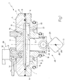
- the plate 8 is bounded axially by two plane surfaces 9, 10 at right angles to the axis 3, the surface 9 being disposed in contact with the surface 6 and having a cylindrical cavity 11 which is obtained through the plate 8 coaxially with respect to the axis 3, and opens externally at the location of the both the surface 9 and the surface 10.
- the cavities 7 and 11 are separated from one another by means of a deformable diaphragm 12 which is made from stainless steel, is welded between the plates 4 and 8 at the location of its peripheral edge, and defines, together with the cavity 7, a variable-volume chamber 13 adapted to contain the petrol provided with an intake ball valve 14 and a delivery ball valve 15 of known type.
- a deformable diaphragm 12 which is made from stainless steel, is welded between the plates 4 and 8 at the location of its peripheral edge, and defines, together with the cavity 7, a variable-volume chamber 13 adapted to contain the petrol provided with an intake ball valve 14 and a delivery ball valve 15 of known type.
- the device 23 comprises a spring 24, which is keyed on the piston 18 coaxially with respect to the axis 3, and is interposed between the plate 8 and the piston 18 in order to provide this piston 18 with its outward stroke, and a cam 25 which is mounted in a rotary manner to rotate about its longitudinal axis 26 perpendicular to the axis 3, and cooperates with a tappet roller 27 coupled in a rotary and axially fixed manner to the piston 18 in order to provide this piston 18 with its return stroke.
- the diaphragm 12, the chamber 20, the piston 18 and the actuation device 23 form a pumping device 28 adapted to use the oil in the chamber 20 to deform the diaphragm 12 and thus to vary the volume of the chamber 13.
- the deformation of the diaphragm 12 is controlled selectively by providing the diaphragm 12 and the piston 18 such that the value of the ratio between the surface of the diaphragm 12 and the surface of the face 19 is at least equal to five.
- the opening of the valve 15 during the return stroke of the piston 18 and, therefore, the quantity of petrol supplied via the valve 15 at each operating cycle of the pump 1 are controlled selectively by a flow regulation device 29 comprising an electromagnetic actuator 30 mounted at the location of the valve 14.
- the actuator 30 comprises an output rod 31 which extends within the valve 14 parallel to the axis 3, and is mounted in a sliding manner in order to move between an operating position (shown in dashed lines in the accompanying Figure), in which the rod 31 is disposed so as to cause the opening of the valve 14, and a rest position (shown in continuous lines in the accompanying Figure), in which the rod 31 is disposed so as to enable the closure of the valve 14.
- valve 15 Since the valve 15 is calibrated so as to open, during the return stroke of the piston 18, only when the valve 14 is closed, the actuation of the actuator 30 makes it possible selectively to control the opening of this valve 15.
- the variant shown in Fig. 2 relates to a pump 32 which differs from the pump 1 in that the intake ball valve 14 is replaced by an intake valve 33 comprising a plate 34 which is mounted at right angles to a longitudinal axis 35 of a duct 36 supplying petrol to the chamber 13 and is provided with a plurality of supply holes 37 obtained through the plate 34 parallel to the axis 35, and a deformable sheet 38 which is secured to the plate 34 at its peripheral edge, is normally disposed in a position closing (Fig. 2) the holes 37, and moves, during the outward stroke of the piston 18, from the closed position to an open position (not shown) of these holes 37 in order to enable the petrol to enter the chamber 13.
- the pump 32 also differs from the pump 1 in that the diaphragm 12 comprises a central portion 39 clamped between two substantially cup-shaped stiffening members 40, one of which (designated hereafter by 40a) is disposed in the chamber 13 and the other of which (designated hereafter by 40b) is disposed in the chamber 20.
- the member 40b is shaped so as to be disposed in contact, during the outward stroke of the piston 18, with a wall 41 bounding the chamber 20 and thus to control the deformation of the diaphragm 12 and is further provided with a plurality of radial channels 42 adapted to enable the oil to pass through the member 40b when this member 40b is disposed in contact with the wall 41.
- the channels 42 are replaced by a plurality of supply channels obtained on the wall 41.
- the valve 43 comprises an outer tubular jacket 47 which is substantially cup-shaped, is housed within the cavity 44 coaxially with respect to the axis 45, and is provided with a plurality of radial holes 48 uniformly distributed about the axis 45 in order to enable oil to be supplied into this jacket 47 and with an axial hole 49.
- the jacket 47 is closed axially by an electromagnet 50 and houses a ball shutter 51 which is coupled in a sliding manner to the jacket 47 and has a ball 52 closing the hole 49.
- the shutter 51 and therefore the ball 52 are normally disposed, under the thrust of a spring 53 interposed between the electromagnet 50 and the shutter 51, in a position (Fig. 2) closing the hole 49, and are displaced by the electromagnet 50, against the action of the spring 53, into a position (not shown) opening the hole 49 in which the oil is supplied to the hole 49 by means of a plurality of supply channels 54 obtained on the outer surface of the ball 52 parallel to the axis 45.
- the electromagnet 50 is excited in order to displace the shutter 51 and therefore the ball 52 into their position opening the hole 49 so as to supply a predetermined initial quantity of oil to the hole 46 and therefore to the chamber 20.
- the initial quantity of oil supplied to the chamber 20 may be maintained constant, in use, by selectively opening the valve 43 in order to supply the chamber 20 with a quantity of oil substantially equal to the quantity of oil emerging from time to time from the chamber 20 as a result of leakage between the portion 17 and the piston 18.
- valve 43 within the oil supply circuit to the chamber 20 makes it possible to supply the petrol suctioned into the chamber 13 directly to the delivery valve 15 and to prevent, in contrast to what happens when using the electromagnetic actuator 30, the losses of energy deriving from the reflux of the petrol suctioned into the chamber 13 through the intake valve 14.
Landscapes
- Engineering & Computer Science (AREA)
- Mechanical Engineering (AREA)
- General Engineering & Computer Science (AREA)
- Reciprocating Pumps (AREA)
- Fuel-Injection Apparatus (AREA)
Priority Applications (1)
| Application Number | Priority Date | Filing Date | Title |
|---|---|---|---|
| PL04105725T PL1536137T3 (pl) | 2003-11-25 | 2004-11-12 | Pompa paliwowa do silnika spalinowego |
Applications Claiming Priority (4)
| Application Number | Priority Date | Filing Date | Title |
|---|---|---|---|
| ITBO20030712 | 2003-11-25 | ||
| ITBO20030712 ITBO20030712A1 (it) | 2003-11-25 | 2003-11-25 | Pompa carburante per un motore a combustione interna. |
| ITBO20040141 | 2004-03-12 | ||
| ITBO20040141 ITBO20040141A1 (it) | 2004-03-12 | 2004-03-12 | Pompa carburante per un motore a combustione interna |
Publications (2)
| Publication Number | Publication Date |
|---|---|
| EP1536137A1 true EP1536137A1 (de) | 2005-06-01 |
| EP1536137B1 EP1536137B1 (de) | 2006-10-25 |
Family
ID=34466446
Family Applications (1)
| Application Number | Title | Priority Date | Filing Date |
|---|---|---|---|
| EP04105725A Expired - Lifetime EP1536137B1 (de) | 2003-11-25 | 2004-11-12 | Kraftstoffpumpe für eine Brennkraftmaschine |
Country Status (9)
| Country | Link |
|---|---|
| US (1) | US20050207912A1 (de) |
| EP (1) | EP1536137B1 (de) |
| CN (1) | CN100572792C (de) |
| AT (1) | ATE343725T1 (de) |
| BR (1) | BRPI0405310A (de) |
| DE (1) | DE602004002920T2 (de) |
| ES (1) | ES2273166T3 (de) |
| PL (1) | PL1536137T3 (de) |
| PT (1) | PT1536137E (de) |
Cited By (2)
| Publication number | Priority date | Publication date | Assignee | Title |
|---|---|---|---|---|
| WO2006058801A1 (de) * | 2004-11-30 | 2006-06-08 | Robert Bosch Gmbh | Membranpumpe und membranpumpenmembran |
| US9885264B2 (en) | 2009-09-30 | 2018-02-06 | Bombardier Recreational Products Inc. | Electronic oil pump |
Families Citing this family (12)
| Publication number | Priority date | Publication date | Assignee | Title |
|---|---|---|---|---|
| US7677155B2 (en) * | 2006-01-13 | 2010-03-16 | Gm Global Technology Operations, Inc. | Statically sealed high pressure fuel pump and method |
| US7794141B2 (en) * | 2006-04-14 | 2010-09-14 | Deka Products Limited Partnership | Thermal and coductivity sensing systems, devices and methods |
| US7861682B2 (en) * | 2007-10-25 | 2011-01-04 | Ford Global Technologies, Llc | Systems and methods for managing camshaft torsional loading |
| GB2470348B (en) * | 2009-04-29 | 2011-06-08 | Flotronic Pumps Ltd | Double-diaphragm pump with unidirectional valve arrangement |
| CN102278587B (zh) * | 2011-07-07 | 2014-10-08 | 北京中清能发动机技术有限公司 | 往复-旋转运动转换机构的机油泵、机油泵本体及设备 |
| CN102536568A (zh) * | 2012-02-08 | 2012-07-04 | 武汉科技大学 | 一种二甲醚发动机用直列隔膜式加压泵 |
| JP5871742B2 (ja) * | 2012-07-30 | 2016-03-01 | 本田技研工業株式会社 | 内燃機関の燃料供給装置 |
| ITRM20130459A1 (it) * | 2013-08-05 | 2015-02-06 | Seko Spa | Pompa autocalibrante con ritorno a molla, in particolare pompa dosatrice autocalibrante con ritorno a molla |
| CN104533777A (zh) * | 2014-12-30 | 2015-04-22 | 米顿罗工业设备(上海)有限公司 | 一种金属隔膜破裂检测结构 |
| DE102016015110A1 (de) * | 2016-12-20 | 2018-06-21 | Fresenius Medical Care Deutschland Gmbh | Verdrängerpumpe für medizinische Flüssigkeiten und Blutbehandlungsvorrichtung mit einer Verdrängerpumpe für medizinische Flüssigkeiten sowie Verfahren zur Steuerung einer Verdrängerpumpe für mediizinische Flüssigkeiten |
| CN114728281B (zh) * | 2019-10-18 | 2023-11-03 | 瞬知(广州)健康科技有限公司 | 用于输注流体的系统和方法 |
| CN112761842A (zh) * | 2020-12-29 | 2021-05-07 | 余姚市舒春机械有限公司 | 一种电喷柴油机一体式燃油泵 |
Citations (5)
| Publication number | Priority date | Publication date | Assignee | Title |
|---|---|---|---|---|
| GB849557A (en) * | 1955-09-22 | 1960-09-28 | Reiners Walter | Improvements in or relating to diaphragm pumps |
| US5520523A (en) * | 1992-06-22 | 1996-05-28 | Nippondenso Co., Ltd. | Diaphragm-type pump |
| US6071089A (en) * | 1998-02-20 | 2000-06-06 | General Motors Corporation | Hydraulic diaphragm pump |
| EP1241338A2 (de) * | 2001-03-15 | 2002-09-18 | Hitachi, Ltd. | Kraftstoffversorgungssystem |
| US6554578B1 (en) * | 1998-06-16 | 2003-04-29 | Bran & Luebbe Gmbh | Diaphragm pump and device for controlling same |
Family Cites Families (1)
| Publication number | Priority date | Publication date | Assignee | Title |
|---|---|---|---|---|
| US4791535A (en) * | 1988-02-11 | 1988-12-13 | Sclafani Vincent J | Security device for fog lights |
-
2004
- 2004-11-12 DE DE602004002920T patent/DE602004002920T2/de not_active Expired - Lifetime
- 2004-11-12 PL PL04105725T patent/PL1536137T3/pl unknown
- 2004-11-12 EP EP04105725A patent/EP1536137B1/de not_active Expired - Lifetime
- 2004-11-12 ES ES04105725T patent/ES2273166T3/es not_active Expired - Lifetime
- 2004-11-12 AT AT04105725T patent/ATE343725T1/de not_active IP Right Cessation
- 2004-11-12 PT PT04105725T patent/PT1536137E/pt unknown
- 2004-11-18 US US10/991,564 patent/US20050207912A1/en not_active Abandoned
- 2004-11-24 BR BR0405310-9A patent/BRPI0405310A/pt not_active IP Right Cessation
- 2004-11-24 CN CNB2004100916527A patent/CN100572792C/zh not_active Expired - Fee Related
Patent Citations (5)
| Publication number | Priority date | Publication date | Assignee | Title |
|---|---|---|---|---|
| GB849557A (en) * | 1955-09-22 | 1960-09-28 | Reiners Walter | Improvements in or relating to diaphragm pumps |
| US5520523A (en) * | 1992-06-22 | 1996-05-28 | Nippondenso Co., Ltd. | Diaphragm-type pump |
| US6071089A (en) * | 1998-02-20 | 2000-06-06 | General Motors Corporation | Hydraulic diaphragm pump |
| US6554578B1 (en) * | 1998-06-16 | 2003-04-29 | Bran & Luebbe Gmbh | Diaphragm pump and device for controlling same |
| EP1241338A2 (de) * | 2001-03-15 | 2002-09-18 | Hitachi, Ltd. | Kraftstoffversorgungssystem |
Cited By (2)
| Publication number | Priority date | Publication date | Assignee | Title |
|---|---|---|---|---|
| WO2006058801A1 (de) * | 2004-11-30 | 2006-06-08 | Robert Bosch Gmbh | Membranpumpe und membranpumpenmembran |
| US9885264B2 (en) | 2009-09-30 | 2018-02-06 | Bombardier Recreational Products Inc. | Electronic oil pump |
Also Published As
| Publication number | Publication date |
|---|---|
| CN1621677A (zh) | 2005-06-01 |
| CN100572792C (zh) | 2009-12-23 |
| ATE343725T1 (de) | 2006-11-15 |
| PT1536137E (pt) | 2007-01-31 |
| PL1536137T3 (pl) | 2007-01-31 |
| DE602004002920T2 (de) | 2007-04-26 |
| US20050207912A1 (en) | 2005-09-22 |
| BRPI0405310A (pt) | 2005-07-19 |
| ES2273166T3 (es) | 2007-05-01 |
| EP1536137B1 (de) | 2006-10-25 |
| DE602004002920D1 (de) | 2006-12-07 |
Similar Documents
| Publication | Publication Date | Title |
|---|---|---|
| EP1536137B1 (de) | Kraftstoffpumpe für eine Brennkraftmaschine | |
| KR101401213B1 (ko) | 오프셋 밸브 축을 갖는 다이어프램 펌프 위치 제어 | |
| EP1788231B1 (de) | Hochdruck-Kraftstoffpumpe | |
| CN103597198B (zh) | 用于燃料泵的入口阀设置 | |
| EP0172421A2 (de) | Pumpe mit hin- und hergehendem Kolben | |
| US4982706A (en) | Valve control apparatus having a magnet valve for internal combustion engines | |
| CN1865687B (zh) | 内燃机引擎燃料泵 | |
| KR101077506B1 (ko) | 개선된 효율을 갖는 피스톤 펌프 | |
| US4149831A (en) | Double-acting differential piston supply pump | |
| US6637410B2 (en) | High pressure fuel supply apparatus | |
| EP1227241B1 (de) | Kraftstoffeinspritzventil und damit ausgerüstete Brennkraftmaschine | |
| JPS6047479B2 (ja) | 多連式往復動ポンプ | |
| EP2082135B1 (de) | Aktive rückschlagventile in membranpumpen mit elektromagnetischer ansteuerung | |
| US3645648A (en) | Hydraulic pulse generator | |
| JPS6085273A (ja) | 多連式往復動ポンプ | |
| JPS60147544A (ja) | 分配型燃料噴射ポンプ | |
| EP1236895B1 (de) | Elektromagnetische Pumpe | |
| KR940002071B1 (ko) | 압력상승시간 조정기구를 지닌 자동조정압력식 전자펌프 | |
| US5188074A (en) | Fuel injection pump for internal combustion engines | |
| US4662828A (en) | Fuel injection pump by means of indirect control with elastic accessory | |
| WO2005078271A1 (en) | Actuating mechanism for hydraulically driven pump-injector for internal combustion engines | |
| JP2561653Y2 (ja) | アクチュエータ | |
| US20250237186A1 (en) | Electromagnetic Suction Valve and Fuel Supply Pump | |
| JPH1122648A (ja) | 燃料ポンプ | |
| RU1801783C (ru) | Гидравлический вырубной пресс |
Legal Events
| Date | Code | Title | Description |
|---|---|---|---|
| PUAI | Public reference made under article 153(3) epc to a published international application that has entered the european phase |
Free format text: ORIGINAL CODE: 0009012 |
|
| AK | Designated contracting states |
Kind code of ref document: A1 Designated state(s): AT BE BG CH CY CZ DE DK EE ES FI FR GB GR HU IE IS IT LI LU MC NL PL PT RO SE SI SK TR |
|
| AX | Request for extension of the european patent |
Extension state: AL HR LT LV MK YU |
|
| 17P | Request for examination filed |
Effective date: 20051129 |
|
| AKX | Designation fees paid |
Designated state(s): AT BE BG CH CY CZ DE DK EE ES FI FR GB GR HU IE IS IT LI LU MC NL PL PT RO SE SI SK TR |
|
| GRAP | Despatch of communication of intention to grant a patent |
Free format text: ORIGINAL CODE: EPIDOSNIGR1 |
|
| GRAS | Grant fee paid |
Free format text: ORIGINAL CODE: EPIDOSNIGR3 |
|
| GRAA | (expected) grant |
Free format text: ORIGINAL CODE: 0009210 |
|
| AK | Designated contracting states |
Kind code of ref document: B1 Designated state(s): AT BE BG CH CY CZ DE DK EE ES FI FR GB GR HU IE IS IT LI LU MC NL PL PT RO SE SI SK TR |
|
| PG25 | Lapsed in a contracting state [announced via postgrant information from national office to epo] |
Ref country code: IT Free format text: LAPSE BECAUSE OF FAILURE TO SUBMIT A TRANSLATION OF THE DESCRIPTION OR TO PAY THE FEE WITHIN THE PRESCRIBED TIME-LIMIT;WARNING: LAPSES OF ITALIAN PATENTS WITH EFFECTIVE DATE BEFORE 2007 MAY HAVE OCCURRED AT ANY TIME BEFORE 2007. THE CORRECT EFFECTIVE DATE MAY BE DIFFERENT FROM THE ONE RECORDED. Effective date: 20061025 Ref country code: NL Free format text: LAPSE BECAUSE OF FAILURE TO SUBMIT A TRANSLATION OF THE DESCRIPTION OR TO PAY THE FEE WITHIN THE PRESCRIBED TIME-LIMIT Effective date: 20061025 Ref country code: FI Free format text: LAPSE BECAUSE OF FAILURE TO SUBMIT A TRANSLATION OF THE DESCRIPTION OR TO PAY THE FEE WITHIN THE PRESCRIBED TIME-LIMIT Effective date: 20061025 Ref country code: AT Free format text: LAPSE BECAUSE OF FAILURE TO SUBMIT A TRANSLATION OF THE DESCRIPTION OR TO PAY THE FEE WITHIN THE PRESCRIBED TIME-LIMIT Effective date: 20061025 Ref country code: SI Free format text: LAPSE BECAUSE OF FAILURE TO SUBMIT A TRANSLATION OF THE DESCRIPTION OR TO PAY THE FEE WITHIN THE PRESCRIBED TIME-LIMIT Effective date: 20061025 Ref country code: LI Free format text: LAPSE BECAUSE OF FAILURE TO SUBMIT A TRANSLATION OF THE DESCRIPTION OR TO PAY THE FEE WITHIN THE PRESCRIBED TIME-LIMIT Effective date: 20061025 Ref country code: CZ Free format text: LAPSE BECAUSE OF FAILURE TO SUBMIT A TRANSLATION OF THE DESCRIPTION OR TO PAY THE FEE WITHIN THE PRESCRIBED TIME-LIMIT Effective date: 20061025 Ref country code: RO Free format text: LAPSE BECAUSE OF FAILURE TO SUBMIT A TRANSLATION OF THE DESCRIPTION OR TO PAY THE FEE WITHIN THE PRESCRIBED TIME-LIMIT Effective date: 20061025 Ref country code: BE Free format text: LAPSE BECAUSE OF FAILURE TO SUBMIT A TRANSLATION OF THE DESCRIPTION OR TO PAY THE FEE WITHIN THE PRESCRIBED TIME-LIMIT Effective date: 20061025 Ref country code: SK Free format text: LAPSE BECAUSE OF FAILURE TO SUBMIT A TRANSLATION OF THE DESCRIPTION OR TO PAY THE FEE WITHIN THE PRESCRIBED TIME-LIMIT Effective date: 20061025 Ref country code: CH Free format text: LAPSE BECAUSE OF FAILURE TO SUBMIT A TRANSLATION OF THE DESCRIPTION OR TO PAY THE FEE WITHIN THE PRESCRIBED TIME-LIMIT Effective date: 20061025 |
|
| REG | Reference to a national code |
Ref country code: GB Ref legal event code: FG4D |
|
| PG25 | Lapsed in a contracting state [announced via postgrant information from national office to epo] |
Ref country code: IE Free format text: LAPSE BECAUSE OF NON-PAYMENT OF DUE FEES Effective date: 20061113 |
|
| REG | Reference to a national code |
Ref country code: CH Ref legal event code: EP |
|
| REG | Reference to a national code |
Ref country code: IE Ref legal event code: FG4D |
|
| PG25 | Lapsed in a contracting state [announced via postgrant information from national office to epo] |
Ref country code: MC Free format text: LAPSE BECAUSE OF NON-PAYMENT OF DUE FEES Effective date: 20061130 |
|
| REF | Corresponds to: |
Ref document number: 602004002920 Country of ref document: DE Date of ref document: 20061207 Kind code of ref document: P |
|
| REG | Reference to a national code |
Ref country code: SE Ref legal event code: TRGR |
|
| PG25 | Lapsed in a contracting state [announced via postgrant information from national office to epo] |
Ref country code: BG Free format text: LAPSE BECAUSE OF FAILURE TO SUBMIT A TRANSLATION OF THE DESCRIPTION OR TO PAY THE FEE WITHIN THE PRESCRIBED TIME-LIMIT Effective date: 20070125 Ref country code: DK Free format text: LAPSE BECAUSE OF FAILURE TO SUBMIT A TRANSLATION OF THE DESCRIPTION OR TO PAY THE FEE WITHIN THE PRESCRIBED TIME-LIMIT Effective date: 20070125 |
|
| REG | Reference to a national code |
Ref country code: PL Ref legal event code: T3 Ref country code: PT Ref legal event code: SC4A Free format text: AVAILABILITY OF NATIONAL TRANSLATION Effective date: 20061123 |
|
| PG25 | Lapsed in a contracting state [announced via postgrant information from national office to epo] |
Ref country code: IS Free format text: LAPSE BECAUSE OF FAILURE TO SUBMIT A TRANSLATION OF THE DESCRIPTION OR TO PAY THE FEE WITHIN THE PRESCRIBED TIME-LIMIT Effective date: 20070225 |
|
| NLV1 | Nl: lapsed or annulled due to failure to fulfill the requirements of art. 29p and 29m of the patents act | ||
| ET | Fr: translation filed | ||
| REG | Reference to a national code |
Ref country code: CH Ref legal event code: PL |
|
| REG | Reference to a national code |
Ref country code: ES Ref legal event code: FG2A Ref document number: 2273166 Country of ref document: ES Kind code of ref document: T3 |
|
| PLBE | No opposition filed within time limit |
Free format text: ORIGINAL CODE: 0009261 |
|
| STAA | Information on the status of an ep patent application or granted ep patent |
Free format text: STATUS: NO OPPOSITION FILED WITHIN TIME LIMIT |
|
| 26N | No opposition filed |
Effective date: 20070726 |
|
| PG25 | Lapsed in a contracting state [announced via postgrant information from national office to epo] |
Ref country code: GR Free format text: LAPSE BECAUSE OF FAILURE TO SUBMIT A TRANSLATION OF THE DESCRIPTION OR TO PAY THE FEE WITHIN THE PRESCRIBED TIME-LIMIT Effective date: 20070126 |
|
| PG25 | Lapsed in a contracting state [announced via postgrant information from national office to epo] |
Ref country code: EE Free format text: LAPSE BECAUSE OF FAILURE TO SUBMIT A TRANSLATION OF THE DESCRIPTION OR TO PAY THE FEE WITHIN THE PRESCRIBED TIME-LIMIT Effective date: 20061025 |
|
| PG25 | Lapsed in a contracting state [announced via postgrant information from national office to epo] |
Ref country code: TR Free format text: LAPSE BECAUSE OF FAILURE TO SUBMIT A TRANSLATION OF THE DESCRIPTION OR TO PAY THE FEE WITHIN THE PRESCRIBED TIME-LIMIT Effective date: 20061025 Ref country code: HU Free format text: LAPSE BECAUSE OF FAILURE TO SUBMIT A TRANSLATION OF THE DESCRIPTION OR TO PAY THE FEE WITHIN THE PRESCRIBED TIME-LIMIT Effective date: 20070426 Ref country code: LU Free format text: LAPSE BECAUSE OF NON-PAYMENT OF DUE FEES Effective date: 20061112 |
|
| PG25 | Lapsed in a contracting state [announced via postgrant information from national office to epo] |
Ref country code: CY Free format text: LAPSE BECAUSE OF FAILURE TO SUBMIT A TRANSLATION OF THE DESCRIPTION OR TO PAY THE FEE WITHIN THE PRESCRIBED TIME-LIMIT Effective date: 20061025 |
|
| PGFP | Annual fee paid to national office [announced via postgrant information from national office to epo] |
Ref country code: ES Payment date: 20091106 Year of fee payment: 6 Ref country code: SE Payment date: 20091027 Year of fee payment: 6 |
|
| PGFP | Annual fee paid to national office [announced via postgrant information from national office to epo] |
Ref country code: PL Payment date: 20091110 Year of fee payment: 6 |
|
| PGFP | Annual fee paid to national office [announced via postgrant information from national office to epo] |
Ref country code: PT Payment date: 20091109 Year of fee payment: 6 |
|
| PGFP | Annual fee paid to national office [announced via postgrant information from national office to epo] |
Ref country code: GB Payment date: 20091102 Year of fee payment: 6 |
|
| REG | Reference to a national code |
Ref country code: PT Ref legal event code: MM4A Free format text: LAPSE DUE TO NON-PAYMENT OF FEES Effective date: 20110512 |
|
| REG | Reference to a national code |
Ref country code: SE Ref legal event code: EUG |
|
| GBPC | Gb: european patent ceased through non-payment of renewal fee |
Effective date: 20101112 |
|
| PG25 | Lapsed in a contracting state [announced via postgrant information from national office to epo] |
Ref country code: PT Free format text: LAPSE BECAUSE OF NON-PAYMENT OF DUE FEES Effective date: 20110512 |
|
| PG25 | Lapsed in a contracting state [announced via postgrant information from national office to epo] |
Ref country code: SE Free format text: LAPSE BECAUSE OF NON-PAYMENT OF DUE FEES Effective date: 20101113 |
|
| PG25 | Lapsed in a contracting state [announced via postgrant information from national office to epo] |
Ref country code: GB Free format text: LAPSE BECAUSE OF NON-PAYMENT OF DUE FEES Effective date: 20101112 |
|
| REG | Reference to a national code |
Ref country code: ES Ref legal event code: FD2A Effective date: 20120110 |
|
| PG25 | Lapsed in a contracting state [announced via postgrant information from national office to epo] |
Ref country code: ES Free format text: LAPSE BECAUSE OF NON-PAYMENT OF DUE FEES Effective date: 20101113 |
|
| REG | Reference to a national code |
Ref country code: PL Ref legal event code: LAPE |
|
| PG25 | Lapsed in a contracting state [announced via postgrant information from national office to epo] |
Ref country code: PL Free format text: LAPSE BECAUSE OF NON-PAYMENT OF DUE FEES Effective date: 20101112 |
|
| PGFP | Annual fee paid to national office [announced via postgrant information from national office to epo] |
Ref country code: DE Payment date: 20131022 Year of fee payment: 10 Ref country code: FR Payment date: 20131121 Year of fee payment: 10 |
|
| REG | Reference to a national code |
Ref country code: DE Ref legal event code: R119 Ref document number: 602004002920 Country of ref document: DE |
|
| REG | Reference to a national code |
Ref country code: FR Ref legal event code: ST Effective date: 20150731 |
|
| PG25 | Lapsed in a contracting state [announced via postgrant information from national office to epo] |
Ref country code: DE Free format text: LAPSE BECAUSE OF NON-PAYMENT OF DUE FEES Effective date: 20150602 |
|
| PG25 | Lapsed in a contracting state [announced via postgrant information from national office to epo] |
Ref country code: FR Free format text: LAPSE BECAUSE OF NON-PAYMENT OF DUE FEES Effective date: 20141201 |