EP1536136A2 - Pompe - Google Patents
Pompe Download PDFInfo
- Publication number
- EP1536136A2 EP1536136A2 EP04027689A EP04027689A EP1536136A2 EP 1536136 A2 EP1536136 A2 EP 1536136A2 EP 04027689 A EP04027689 A EP 04027689A EP 04027689 A EP04027689 A EP 04027689A EP 1536136 A2 EP1536136 A2 EP 1536136A2
- Authority
- EP
- European Patent Office
- Prior art keywords
- pump
- housing
- channel
- membrane
- impeller
- Prior art date
- Legal status (The legal status is an assumption and is not a legal conclusion. Google has not performed a legal analysis and makes no representation as to the accuracy of the status listed.)
- Granted
Links
Images


Classifications
-
- F—MECHANICAL ENGINEERING; LIGHTING; HEATING; WEAPONS; BLASTING
- F04—POSITIVE - DISPLACEMENT MACHINES FOR LIQUIDS; PUMPS FOR LIQUIDS OR ELASTIC FLUIDS
- F04B—POSITIVE-DISPLACEMENT MACHINES FOR LIQUIDS; PUMPS
- F04B43/00—Machines, pumps, or pumping installations having flexible working members
- F04B43/02—Machines, pumps, or pumping installations having flexible working members having plate-like flexible members, e.g. diaphragms
-
- F—MECHANICAL ENGINEERING; LIGHTING; HEATING; WEAPONS; BLASTING
- F04—POSITIVE - DISPLACEMENT MACHINES FOR LIQUIDS; PUMPS FOR LIQUIDS OR ELASTIC FLUIDS
- F04B—POSITIVE-DISPLACEMENT MACHINES FOR LIQUIDS; PUMPS
- F04B23/00—Pumping installations or systems
- F04B23/04—Combinations of two or more pumps
- F04B23/08—Combinations of two or more pumps the pumps being of different types
Definitions
- the invention relates to a pump arrangement for a Reverse osmosis system with a pump housing and with an am Pump housing provided intake manifold and outlet.
- the invention is based on the object, a pump assembly such form and arrange that with small Mass flow for the reverse osmosis advantageous flow conditions are adjustable and the pump assembly cheap is to produce.
- the Pump assembly having a shaft, wherein on a first Part of the shaft, a first impeller and on a second Part of the shaft is a drive for a high-pressure piston pump is arranged.
- the first moving the mass or liquid flow impeller has the advantage over a piston pump that the mass flow is not pulsating promoted and a critical flow velocity in the membrane is not exceeded, as is the case with piston pumps during the charge cycle.
- the second impeller or the drive for the high-pressure piston pump according to the invention is arranged in the same pump housing as the first impeller and is driven by the same rotating shaft as the first impeller. The inventive design is cheaper and simpler due to the simple control without pressure differential valve and the almost wear-free rotating pumps.
- the pump assembly in an open and / or closed circuit for a liquid is integrated.
- This will achieve that the pump arrangement according to the invention simultaneously in various arrangements of circuits can be integrated. It is a closed circuit with one or more Combined open circuits, over which a mass flow is added or removed.
- the pump assembly is a system with at least one closed and at least one open Cycle forms.
- the closed circuit is a membrane brought in.
- the medium gets high for reverse osmosis necessary pressure level circulated.
- About one open circuit becomes the closed circuit constantly supplied to a mass flow at one or more locations is removed again at the closed circuit.
- the intake manifold and the Outlet are associated with the first impeller and the first impeller closes the circuit.
- the closed Circulation thus becomes the fluid through the first impeller circulated under high pressure level. This will achieve that with the first impeller the liquid in Circulation is only circulated.
- the first impeller is not for applying the necessary for the reverse osmosis high pressure levels used.
- the piston high-pressure pump a Inlet and an outlet is associated with the outlet communicates with the circuit via a line.
- the circuit is continuously with the second impeller or with the high-pressure piston pump a certain Mass flow of liquid supplied to the other Place the circuit is removed again. This mass flow is over the inlet designed as an intake fed.
- the first impeller is designed as a low pressure pump and the first Impeller a pressure difference up to 7 bar is adjustable. To circulate the circulation are essentially only the Flow and friction losses through the first impeller applied.
- the first impeller as a rotating hydrodynamic or hydrostatic pump such as a centrifugal pump, Impeller pump or vane pump formed is.
- all rotating pumps can be used, the an approximately continuous fluid flow without Generate charge change.
- the second impeller as Piston high-pressure pump is formed and the second impeller or at the high-pressure piston pump a pressure difference is adjustable up to 100 bar. This ensures that generates the required pressure level for the reverse osmosis and at the same time allows an exchange of liquids is, so that the salt concentration in the circulation does not exceed a certain level.
- the second pump as rotating hydrostatic positive displacement pump such as a vane pump, gear pump, Roots pump or rotary piston pump is formed.
- rotating hydrostatic positive displacement pump such as a vane pump, gear pump, Roots pump or rotary piston pump
- they are all rotating pumps can be used, which is a corresponding Generate pressure level.
- the high-pressure piston pump as an oscillating hydrostatic positive displacement pump such as a piston pump or a piston hydraulic diaphragm pump is trained.
- all oscillating pumps can be used, which is a corresponding Generate pressure level.
- the second part of the shaft as a cam, cranked or as a swash plate as medium or direct drive for at least one in the radial direction to a rotational axis movable piston of the high-pressure piston pump is trained.
- the drive is a cam designed for a piston.
- the wave at least integrally formed with the first impeller and with the Drive is mounted in the pump housing, wherein the pump housing formed in one piece, screwed or cast is. Both pumps are thus immediately adjacent to each other arranged a pump housing.
- the pump housing is compact educated.
- the shaft at least is formed in two parts and the first part of the shaft with the first impeller in a first housing body and the second part of the shaft with the drive in a second from stored first housing body structurally separate housing body is. This will cause the waves to move according to Training the pump made and only during assembly be connected at least rotatably.
- the first part and the second part does not connect inside the case. Thereby is achieved that the first housing body in terms the different pressure levels at the two Pumps opposite second housing body connected is.
- the two shaft parts are via an intermediate shaft or via a chain or belt drive with each other connected. For such an external connection of the two Shaft parts, it is advantageous, the two shaft parts not in flight but in parallel to each other, what brings a chain or belt drive used.
- the second impeller is on the shaft is stored in a pump room and the pump room the inlet and the outlet is assigned, wherein the Outlet connected via a line to the circuit stands. This is compared with the above oscillating pump a rotating, building up the high pressure Pump integrated into the circuit via the outlet. Over the inlet is a feeder for still to be filtered Liquid formed.
- the circuit medium or directly an inlet, a drain and a withdrawal nozzle assigned.
- the inlet is a certain Mass flow of liquid still to be filtered added. This Mass flow corresponds to the sum of the expiration and the Outlet neck discharged mass flow. At the withdrawal nozzle if filtered or treated liquid is removed, whereas concentrate drains off at the drain.
- the inlet is designed as an inlet. This will achieved a simple structure.
- the outlet is designed as a drain is and / or the second impeller or the first Impeller can be used as a hydraulic motor. This will achieve that the high pressure level in various ways is used to drive the high-pressure element.
- the shaft third impeller or a second piston and impeller or the second piston an inlet and an outlet on the pump housing or is assigned to the housing body, wherein the Drain of the circuit is connected to the inlet and / or the impeller or the second piston as a hydraulic motor can be used.
- the Drain of the circuit is connected to the inlet and / or the impeller or the second piston as a hydraulic motor can be used.
- first impeller and the second impeller as vane rotor or rotating positive displacement pump formed are, wherein the second impeller associated with the outlet nozzle and the intake manifold associated with the first impeller connected via the open circuit and the Outlet of the first impeller over an open volume a liquid with the inlet of the second impeller connected is.
- This will be a booster module formed, which works without valves.
- the inlet of at least a pump impeller hydraulically with an external pump or a pressure line is connected and the impeller via the external pump or the pressure line hydraulically driven is.
- This will be an alternative to the drive via a created rotating shaft.
- a third pump element is assigned to the shaft.
- the third pump element is connected to an existing pump circuit connect, via which the drive of the pump assembly he follows.
- the third impeller drivable via the cooling water circuit of a marine engine.
- the deliverable volume flow of the second impeller greater than or different than the can be conveyed volume flow of the first impeller and this difference volume flow between 80 and 100% of the am Removal nozzle corresponds to removable flow.
- At least one part at least a housing and / or a component of the invention Arrangement of chemically resistant material such as For example, saltwater resistant steel, saltwater resistant Bronze and / or plastic is formed.
- chemically resistant material such as For example, saltwater resistant steel, saltwater resistant Bronze and / or plastic is formed.
- Steel can be used for example V4A® or AISI316®.
- At least one part at least a housing and / or a component of the invention Arrangement is coated. This will achieve that the pump assembly is seawater resistant, regardless of the base material is.
- At least one part at least a housing and / or a component of the invention Arrangement for example by electrolytic oxidation, by chemical application or by electrolytic coated metal is coated.
- electrolytic oxidation by chemical application or by electrolytic coated metal is coated.
- nickel chemically applied or an electrolytic Coating of chrome, nickel, silver or gold educated is coated.
- the filter element as a filter or is designed as a membrane.
- the membrane allows the use for reverse osmosis.
- the delivery rate at the sampling nozzle between 1 and 50 liters per hour, in particular between 5 and 20 liters per hour.
- the invention also relates to a reverse osmosis system with at least two pumps mounted in a housing, a circuit integrated into the one of the two pumps and at least one integrated into the cycle Diaphragm, wherein a control valve is provided.
- the task is solved by the fact that in addition to the Both pumps, the control valve and the membrane in one one or more parts housing are arranged.
- the housing is a high-pressure housing, a control housing and a filter housing, wherein in the high-pressure housing, the shaft and the high-pressure piston pump, in the control housing, the control valve and in the filter housing the membrane are arranged or stored.
- the Three sub-housings can be made with the help of clamps or bolts be assembled into a housing.
- the housing is made of a seawater resistant Plastic or metal formed and the housing and the Shaft to a motor (13) are flanged.
- plastic can be mechanically very easy to handle and points in terms the required pressure a sufficiently high Elastic modulus on.
- the high-pressure piston pump has a cylinder and the cylinder is inserted into the housing is.
- the cylinder is made of a wear-resistant metal or made of ceramic.
- the tread be coated for the piston.
- the high pressure housing has a bore having the high-pressure piston pump with the centrifugal pump combines. The shorter this connection, the more efficient the system works.
- the actual pump housing for the centrifugal impeller is provided in the control housing.
- control housing in a first position closes the drain opposite the flushing channel and in one second position the membrane channel opposite the inlet channel closes. In the first position, the control housing only be flowed through in a channel. In the second Position, however, in two channels.
- a pressure relief valve Proceed is over which the overpressure channel controlled closed is.
- the pressure relief valve is electromagnetic or manually controllable.
- the permeate from the Suction container sucked through the flushing channel and over the Inlet of the membrane supplied and then from Membrane via a membrane channel and an outlet are removed becomes.
- the permeate flows through the membrane in the
- the permeate flows through the membrane in the same Direction as in winning drinking water.
- FIGS. 1 to 7 show different variants of Pump assemblies 3 according to the invention shown for the principles of action shown in Figures 8 to 11 can be used.
- the principles of action are in the manner of a circuit 1, namely in closed circuits 1 according to the figures 8 and 9 and in open circuits 1 according to FIGS. 10 and 11 to distinguish.
- a filter element 12 integrated into a circuit 1, which is circulated via a first impeller 6.
- the first Impeller 6 is as a centrifugal or vane pump educated.
- the liquid medium in this cycle 1 depends on the type of medium under a pressure of 5 bis 100 bar.
- the medium is relative to a preferred embodiment Brackish water or sea or salt water.
- the pressure of 5 to 100 bar is replaced by a second Pump wheel 7 generated.
- the circuit 1 is steadily via a feed 1.1 a volume flow of brackish or sea water from an open volume 15 supplied via the second impeller 7.
- the same Volume flow is in the sum of a run 1.2 and taken from a sampling port 1.3 of the circuit 1. For this is via the sampling port 1.3 to the filter element 12 pure water and at the expiry 1.2 retentate or concentrated brackish or seawater taken.
- the second impeller 7 is for generation high pressure level as a vane pump or designed as a piston pump. Both are according to the invention Pump wheels 6, 7 connected via a shaft 5 and are over the shaft 5 is driven by a motor 13.
- FIG. 9 shows, in addition to the above described structure a way of energy recovery.
- the impeller 14 the retentate from the high pressure level to ambient pressure.
- open circuit 1 is the filter element 12 input and output side each via a first Impeller 6 and a second impeller 7 with an open Volume 15 connected.
- the open circuit 1 is opposite the closed only at the withdrawal port 1.3 in the flow direction behind the filter element 12 pure water taken. The introduced via the inlet 1.1 volume flow on brackish or sea water is thus up on the Pure water volume flow through the outlet 1.2 back to the open Volume 15 supplied.
- Connection of the two pump wheels 6, 7 via a Wave 5 is the energy recovery of the high pressure level guaranteed. Apart from the flow and friction losses is in this arrangement, only the amount of energy to raise, by the removal of pure water at Suction nozzle 1.3 is lost.
- the embodiment according to FIG. 11 shows a drive by external pressure.
- the pump assembly 3 is connected according to the invention to any external pump 16 with motor 13.
- the low pressure level of the external pump 16 according to the invention at least sufficient to overcome friction and flow losses in the system.
- the high pressure level required in the system is created by the working as a hydraulic motor and connected via the shaft 5 to the second pump 7 first pump 6.
- Volume flow of the pump 7 and the second pump 7 corresponds to the flow rate of the external pump 16.
- the volume flow of the external pump 16 corresponds to the sum of the volume flow of the pump 6 or of the first pumping wheel and the volume flow at the withdrawal port 1.3. This ensures that the pressure in the system increases, as long as the sampling port 1.3 is closed.
- the volume is taken from or filtered dirt particles as well as losses due to leaks to take into account.
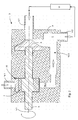
- FIG. 1 A first embodiment of a pump arrangement according to the invention 3 is shown in FIG.
- a shaft 5 is mounted about an axis of rotation 5.1, the first impeller 6 and a drive 8 for a Piston 9a receives.
- the first impeller 6 is considered to be radial compacting centrifugal impeller formed.
- the piston 9a forms a piston high pressure pump.
- This pump assembly 3 is for a closed circuit 1 is provided, which receives a filter element 12 and is circulated by the centrifugal pump 6, see Figure 8-11.
- a closed circuit 1 is within the meaning of the invention the direct connection of an input of the filter element 12 via the first impeller 6 with an output of To understand filter element 12. From the closed Circuit 1 can certainly branch off further circuits or other inflows and outflows may be provided.
- the pressure in the circuit 1 is up to 100 bar and is generated by the piston high-pressure pump 9. This is becoming filtering or through the reverse osmosis process to be cleaned salt or brackish water a cylinder chamber 10th the piston high-pressure pump 9 is supplied via an inlet 10.1. From the cylinder chamber 10, the fluid is via an outlet 10.2 and a line 10.3 fed into the circuit 1.
- the piston 9a of the high pressure piston pump 9 is by means of Nock 8 driven and is by a spring element 9.1 to Cam 8 biased towards.
- the inlet and outlet 10.1, 10.2 is controlled by a respective valve, which by a ball is shown symbolically.
- the outlet 10.2 When sucking fluid through the piston 9a, the outlet 10.2 is closed and the Inlet 10.1 open. During compression, the inlet becomes 10.1 closed and the outlet 10.2 open.
- the oscillating feed of the fluid has according to the invention on the continuously circulated via the centrifugal pump 6 Circuit 1 has no significant influence.
- the amount to fluid, which is fed via the high-pressure piston pump 9 becomes, in the form of retentate and pure water the circulation 1 in the flow direction behind the filter element 12th taken again see Figure 8-9.
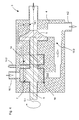
- the high-pressure piston pump 9 by a second impeller 7 is formed.
- the second impeller 7 is formed as a wellgelzellenrad.
- This invention Embodiment of a pump assembly 3 is still simpler in construction than the one described above.
- Inlet 10.1 and the outlet 10.2 are due to the continuous Pumping power of the diegelzellenrads 7 not through a valve closed.
- Both the high pressure stream as well the recirculation flow will be continuous without appreciable impulse fluctuations promoted.
- the pulse fluctuations due the drive of the shaft 5 are, depending on the embodiment if necessary to balance by a flywheel or similar measures.
- the rest of the construction corresponds to that of the pump arrangement 3 according to FIG. 1
- the embodiment according to FIG. 3 has opposite to FIG 1 shows a module for energy recovery according to FIG 9 on.
- a module for energy recovery according to FIG 9 on.
- an inlet 10.1 for the retentate provided via a second piston 9b is relaxed and discharged through an outlet 14.2.
- Inlet 14.1 branches in the flow direction in front of the first impeller 6 off.
- a spool 17 is provided, depending on the position of the second piston 9b the inlet 14.1 or the outlet 14.2 releases.
- the other structure corresponds to the embodiment according to FIG. 1
- the pump arrangement 3 according to FIG Pump assembly 3 of Figure 2 also a module for Recovery of the pressure energy of the retentate.
- the module or the third Impeller 14 is formed as diegelzellenrad.
- the third Impeller 14 for energy recovery is much easier constructed as the arrangement of the second piston 9b with the spool 17.
- the other structure of the pump assembly 3 corresponds to that in Figure 2 and with respect to the inlet 14.1 and the outlet 14.2 that of Figure 3.
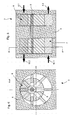
- FIGS. 5 to 7 show pressure-increasing modules, as in open circuits according to the figures 10 and 11 are used.
- the inventive feature that two rotating pumping elements arranged on a shaft 5 are preserved.
- the pressure booster module is used mainly the recovery of the high pressure level.
- the first impeller 6 and the second impeller 7 are as Vane pump wheels formed.
- the first impeller 6 does not serve as in the embodiments according to the figures 1 to 4 as a circulation pump, but as a module for energy recovery.
- FIG. 6 is a sectional view of a vane pump shown.
- FIG. 7 shows a pressure increase module according to the figures 5 and 6.
- the pressure booster module is equipped with a external motor driven. This can be used as a pump or formed based on any other principle be.
- the mass flows and their different Press to feed into circuit 1 and in Circuit 1 through the dimensioning of the individual pump elements to coordinate with each other.
- the invention thereby fixed parameters is an equal number of revolutions for all Pumping organs due to a shaft 5, the different Delivery volumes of the pumping organs the pressure conditions determine.
- pumps with the same volume flow or the same Volume per speed are for generating a high Pressure levels used, the different delivery volumes when using a two-part shaft 5 through different speeds are generated.
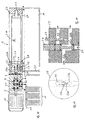
- FIGS. 12 to 14 show a solution for the entire osmosis plant, as for example for the production of drinking water Groundwater or brackish water in third world countries or for the treatment of seawater on pleasure boats and yachts is used.
- the housing 2 shown in Fig. 12 made of plastic formed of three sub-housings arranged side by side are.
- To the high pressure housing 2.1 includes the control housing 2.2 and the filter housing 2.3.
- the high pressure housing 2.1 takes the high-pressure piston pump 9 and is flanged together with the shaft 5 to a motor 13.
- On the opposite side of the engine 13 of the High-pressure housing 2.1 is the centrifugal impeller 6 of the centrifugal pump attached to the shaft 5.
- the membrane 12 is via a mounting flange 2.8 in the control housing 2.2 and a Mounting flange 2.9 fixed in the filter housing 2.3.
- the brackish or seawater to be treated is supplied via the inlet 1.1 and the mechanical pre-filter 11 of the high-pressure piston pump 9 supplied.
- the in a cylinder 9.2 is made of metal, the fluid via a hole 10.3 in the high-pressure housing 2.1 in the housing promoted the centrifugal pump 6, the same time Control housing 2.2 forms.
- Circulation 1 circulated which is necessary for the osmosis has high pressure level.
- the high pressure level is through the piston high-pressure pump 9 is shown.
- the fluid is starting from the inlet channel 2.2a together with the fluid from the High-pressure piston pump 9 through the centrifugal pump 6 in the outlet channel 2.2b promoted.
- the fluid flows into the main channel 2.10 of the filter housing 2.3, attached to the control housing 2.2 connects. From the main channel 2.10 from the fluid flows into the membrane 12. The filtered through the membrane 12 Fluid is called permeate and flows out of the membrane 12 via a removal channel 1.3 from the housing. 2
- the membrane 12 in the receiving flange 2.9 in the filter housing 2.3 stored, the corresponding hole having.
- the circulating and unfiltered fluid Increases concentration in this process can via a trained as a channel expiry 1.2 in the control box 2.2 are derived from the housing 2. For this is the procedure 1.2 via a pressure relief valve with a membrane channel 2.2c connected, the circuit 1 to inlet channel 2.2a closes.
- the membrane 12 can be rinsed after use, is below the housing 2 and der Membrane 12 a Spül matterser 18 arranged and the inlet channel 2.2 a via a Flushing 2.4 and a purge line 2.5 with the volume of Rinse tank 18 connected.
- the rinse tank 18 is at the beginning the osmosis process on the filter housing 2.3 with Permeate filled.
- the rinsing process makes this possible in the rinsing container 18 available permeate instead of highly concentrated Fluids or retentate in the circuit 1 through the membrane To pump 12 and then derive from the housing 2.
- control housing 2.2 and in Figs. 13 and 14 shown control housing are 2.2 not identical. Both have a control valve 2.6, the in the illustrated positions with the membrane channel 2.2c connects to the inlet channel 2.2a. In this position of the Control valve 2.6, it is possible to remove the retentate, is opened in the pressure relief valve 2.7.
- Fig. 13 shows a cross section of the control housing 2.2 according to Fig. 14.
- the operation and the geometry is essential to the invention and in FIGS. 13 and 14 for the Professional presented sufficiently extensive.
- the advantageous ones Dimensions, ratios and sealing measures serve at the same time to explain the operation.
Landscapes
- Engineering & Computer Science (AREA)
- Mechanical Engineering (AREA)
- General Engineering & Computer Science (AREA)
- Separation Using Semi-Permeable Membranes (AREA)
- Reciprocating Pumps (AREA)
- Details Of Reciprocating Pumps (AREA)
- Structures Of Non-Positive Displacement Pumps (AREA)
- Fluid-Driven Valves (AREA)
- Eye Examination Apparatus (AREA)
Applications Claiming Priority (2)
| Application Number | Priority Date | Filing Date | Title |
|---|---|---|---|
| DE10354785A DE10354785A1 (de) | 2003-11-21 | 2003-11-21 | Pumpe |
| DE10354785 | 2003-11-21 |
Publications (3)
| Publication Number | Publication Date |
|---|---|
| EP1536136A2 true EP1536136A2 (fr) | 2005-06-01 |
| EP1536136A3 EP1536136A3 (fr) | 2006-04-05 |
| EP1536136B1 EP1536136B1 (fr) | 2010-07-07 |
Family
ID=34442276
Family Applications (1)
| Application Number | Title | Priority Date | Filing Date |
|---|---|---|---|
| EP04027689A Expired - Lifetime EP1536136B1 (fr) | 2003-11-21 | 2004-11-22 | Pompe |
Country Status (3)
| Country | Link |
|---|---|
| EP (1) | EP1536136B1 (fr) |
| AT (1) | ATE473369T1 (fr) |
| DE (2) | DE10354785A1 (fr) |
Cited By (1)
| Publication number | Priority date | Publication date | Assignee | Title |
|---|---|---|---|---|
| NL1029506C2 (nl) * | 2005-07-13 | 2007-01-16 | Hans Georg Prof Dr Ing Jerie | Filtreerinrichting. |
Citations (4)
| Publication number | Priority date | Publication date | Assignee | Title |
|---|---|---|---|---|
| DE2515785A1 (de) | 1974-04-24 | 1975-10-30 | Messier Hispano Sa | Anordnung zum vermeiden der kavitation bei einer hauptpumpe |
| EP0059275A1 (fr) | 1980-02-20 | 1982-09-08 | Seagold Industries Corporation | Appareil et procédé pour l'osmose inverse à l'aide d'une soupape intégrée |
| DE3719292C1 (de) | 1987-06-10 | 1988-12-29 | Grundfos Internat A S | Pumpvorrichtung zur Aufbereitung von Rohwasser nach dem Prinzip der Umkehrosmose |
| WO2003008076A1 (fr) | 2001-07-16 | 2003-01-30 | Miox Corporation | Systeme de membrane actionne par une pompe a tete double |
Family Cites Families (3)
| Publication number | Priority date | Publication date | Assignee | Title |
|---|---|---|---|---|
| US2349161A (en) * | 1941-08-15 | 1944-05-16 | Interstate Aircraft And Engine | Hydraulic pump |
| DE3941133A1 (de) * | 1989-12-13 | 1991-07-25 | Fresenius Ag | Vorrichtung zur rueckgewinnung von energie bei umkehrosmoseanlagen |
| DE19748997C2 (de) * | 1997-11-06 | 2001-05-23 | Schilling Chemie Gmbh U Produk | Verfahren zum Betrieb einer Umkehrosmoseanlage |
-
2003
- 2003-11-21 DE DE10354785A patent/DE10354785A1/de not_active Withdrawn
-
2004
- 2004-11-22 DE DE502004011360T patent/DE502004011360D1/de not_active Expired - Lifetime
- 2004-11-22 AT AT04027689T patent/ATE473369T1/de active
- 2004-11-22 EP EP04027689A patent/EP1536136B1/fr not_active Expired - Lifetime
Patent Citations (4)
| Publication number | Priority date | Publication date | Assignee | Title |
|---|---|---|---|---|
| DE2515785A1 (de) | 1974-04-24 | 1975-10-30 | Messier Hispano Sa | Anordnung zum vermeiden der kavitation bei einer hauptpumpe |
| EP0059275A1 (fr) | 1980-02-20 | 1982-09-08 | Seagold Industries Corporation | Appareil et procédé pour l'osmose inverse à l'aide d'une soupape intégrée |
| DE3719292C1 (de) | 1987-06-10 | 1988-12-29 | Grundfos Internat A S | Pumpvorrichtung zur Aufbereitung von Rohwasser nach dem Prinzip der Umkehrosmose |
| WO2003008076A1 (fr) | 2001-07-16 | 2003-01-30 | Miox Corporation | Systeme de membrane actionne par une pompe a tete double |
Cited By (1)
| Publication number | Priority date | Publication date | Assignee | Title |
|---|---|---|---|---|
| NL1029506C2 (nl) * | 2005-07-13 | 2007-01-16 | Hans Georg Prof Dr Ing Jerie | Filtreerinrichting. |
Also Published As
| Publication number | Publication date |
|---|---|
| ATE473369T1 (de) | 2010-07-15 |
| EP1536136B1 (fr) | 2010-07-07 |
| DE10354785A1 (de) | 2005-06-23 |
| EP1536136A3 (fr) | 2006-04-05 |
| DE502004011360D1 (de) | 2010-08-19 |
Similar Documents
| Publication | Publication Date | Title |
|---|---|---|
| DE60012530T2 (de) | Kolbenpumpe, verfahren und anlage zum filtrieren von wasser | |
| DE2708311A1 (de) | Vorrichtung zur umkehrosmose- reinigung von wasser oder von anderen medien | |
| DE60315348T2 (de) | Hydraulischer drehzahlsteigernder antrieb für wasserströmungsturbine | |
| DE3141033A1 (de) | Fluessigkeitsfoerdersystem mit energierueckgewinnungseinrichtung | |
| DD267914A5 (de) | Verfahren und vorrichtung zur behandlung von fluessigkeiten mittels membranfilteranlage | |
| EP1204460A1 (fr) | Procede et dispositif pour dessaler de l'eau | |
| DE102009049094A1 (de) | Pumpe für ein Hochdruckreinigungsgerät | |
| DE10066033A1 (de) | Verfahren und Vorrichtung zum Entsalzen von Wasser | |
| EP0055981A1 (fr) | Système de dessalement de l'eau selon le procédé d'osmose inverse | |
| WO1996012125A1 (fr) | Boite de vitesses automatique, notamment pour vehicules a moteur | |
| DE112006000563T5 (de) | Hochdruckpumpe und Verfahren zur Verringerung einer Strömungsmittelvermischung darin | |
| EP1536136A2 (fr) | Pompe | |
| DE102009049095A1 (de) | Pumpe für ein Hochdruckreinigungsgerät | |
| DE102007022022A1 (de) | Hydrostatische Maschine und diese verwendender Wandler | |
| DE3541668A1 (de) | Pumpe | |
| DE4439545A1 (de) | Vorrichtung zur teilweisen Trennung flüssiger Lösungen nach dem Prinzip der Querfiltration | |
| DE102015013916B3 (de) | Vorrichtung zur Wasseraufbereitung | |
| WO1998011979A1 (fr) | Dispositif de pompage pour osmose inverse entraine par un moteur | |
| EP1631369B1 (fr) | Systeme pompe-echangeur de pression d'osmose-inverse | |
| DE102007020298A1 (de) | Kolbenpumpe für ein Hochdruckreinigungsgerät | |
| DE3923722C2 (de) | Kombination von Verdrängerpumpe, insbesondere Kolbenpumpe, und Verdrängermotor, insbesondere Kolbenmotor | |
| DE2850650A1 (de) | Geraet zur durchfuehrung der umkehrosmose | |
| DE102007029326A1 (de) | Kombiniertes Pumpensystem | |
| WO2023006178A1 (fr) | Pompe à piston linéaire sans soupape | |
| DE3831965A1 (de) | Vorrichtung zum entsalzen von fluessigkeiten, vorzugsweise seewasser, nach dem prinzip der umkehr-osmose mit druckuebersetzer |
Legal Events
| Date | Code | Title | Description |
|---|---|---|---|
| PUAI | Public reference made under article 153(3) epc to a published international application that has entered the european phase |
Free format text: ORIGINAL CODE: 0009012 |
|
| AK | Designated contracting states |
Kind code of ref document: A2 Designated state(s): AT BE BG CH CY CZ DE DK EE ES FI FR GB GR HU IE IS IT LI LU MC NL PL PT RO SE SI SK TR |
|
| AX | Request for extension of the european patent |
Extension state: AL HR LT LV MK YU |
|
| RIC1 | Information provided on ipc code assigned before grant |
Ipc: 7F 04B 23/08 B Ipc: 7F 04B 43/02 A Ipc: 7F 04B 23/04 B |
|
| PUAL | Search report despatched |
Free format text: ORIGINAL CODE: 0009013 |
|
| AK | Designated contracting states |
Kind code of ref document: A3 Designated state(s): AT BE BG CH CY CZ DE DK EE ES FI FR GB GR HU IE IS IT LI LU MC NL PL PT RO SE SI SK TR |
|
| AX | Request for extension of the european patent |
Extension state: AL HR LT LV MK YU |
|
| 17P | Request for examination filed |
Effective date: 20061002 |
|
| AKX | Designation fees paid |
Designated state(s): AT BE BG CH CY CZ DE DK EE ES FI FR GB GR HU IE IS IT LI LU MC NL PL PT RO SE SI SK TR |
|
| 17Q | First examination report despatched |
Effective date: 20071122 |
|
| GRAP | Despatch of communication of intention to grant a patent |
Free format text: ORIGINAL CODE: EPIDOSNIGR1 |
|
| GRAS | Grant fee paid |
Free format text: ORIGINAL CODE: EPIDOSNIGR3 |
|
| GRAA | (expected) grant |
Free format text: ORIGINAL CODE: 0009210 |
|
| AK | Designated contracting states |
Kind code of ref document: B1 Designated state(s): AT BE BG CH CY CZ DE DK EE ES FI FR GB GR HU IE IS IT LI LU MC NL PL PT RO SE SI SK TR |
|
| REG | Reference to a national code |
Ref country code: GB Ref legal event code: FG4D Free format text: NOT ENGLISH |
|
| REG | Reference to a national code |
Ref country code: CH Ref legal event code: EP |
|
| REG | Reference to a national code |
Ref country code: IE Ref legal event code: FG4D |
|
| REF | Corresponds to: |
Ref document number: 502004011360 Country of ref document: DE Date of ref document: 20100819 Kind code of ref document: P |
|
| REG | Reference to a national code |
Ref country code: NL Ref legal event code: VDEP Effective date: 20100707 |
|
| PG25 | Lapsed in a contracting state [announced via postgrant information from national office to epo] |
Ref country code: SI Free format text: LAPSE BECAUSE OF FAILURE TO SUBMIT A TRANSLATION OF THE DESCRIPTION OR TO PAY THE FEE WITHIN THE PRESCRIBED TIME-LIMIT Effective date: 20100707 |
|
| PG25 | Lapsed in a contracting state [announced via postgrant information from national office to epo] |
Ref country code: FI Free format text: LAPSE BECAUSE OF FAILURE TO SUBMIT A TRANSLATION OF THE DESCRIPTION OR TO PAY THE FEE WITHIN THE PRESCRIBED TIME-LIMIT Effective date: 20100707 Ref country code: NL Free format text: LAPSE BECAUSE OF FAILURE TO SUBMIT A TRANSLATION OF THE DESCRIPTION OR TO PAY THE FEE WITHIN THE PRESCRIBED TIME-LIMIT Effective date: 20100707 |
|
| PGFP | Annual fee paid to national office [announced via postgrant information from national office to epo] |
Ref country code: AT Payment date: 20101112 Year of fee payment: 7 |
|
| REG | Reference to a national code |
Ref country code: IE Ref legal event code: FD4D |
|
| PG25 | Lapsed in a contracting state [announced via postgrant information from national office to epo] |
Ref country code: CY Free format text: LAPSE BECAUSE OF FAILURE TO SUBMIT A TRANSLATION OF THE DESCRIPTION OR TO PAY THE FEE WITHIN THE PRESCRIBED TIME-LIMIT Effective date: 20100707 Ref country code: BG Free format text: LAPSE BECAUSE OF FAILURE TO SUBMIT A TRANSLATION OF THE DESCRIPTION OR TO PAY THE FEE WITHIN THE PRESCRIBED TIME-LIMIT Effective date: 20101007 Ref country code: PT Free format text: LAPSE BECAUSE OF FAILURE TO SUBMIT A TRANSLATION OF THE DESCRIPTION OR TO PAY THE FEE WITHIN THE PRESCRIBED TIME-LIMIT Effective date: 20101108 Ref country code: PL Free format text: LAPSE BECAUSE OF FAILURE TO SUBMIT A TRANSLATION OF THE DESCRIPTION OR TO PAY THE FEE WITHIN THE PRESCRIBED TIME-LIMIT Effective date: 20100707 Ref country code: IS Free format text: LAPSE BECAUSE OF FAILURE TO SUBMIT A TRANSLATION OF THE DESCRIPTION OR TO PAY THE FEE WITHIN THE PRESCRIBED TIME-LIMIT Effective date: 20101107 |
|
| PGFP | Annual fee paid to national office [announced via postgrant information from national office to epo] |
Ref country code: DE Payment date: 20101119 Year of fee payment: 7 |
|
| PG25 | Lapsed in a contracting state [announced via postgrant information from national office to epo] |
Ref country code: GR Free format text: LAPSE BECAUSE OF FAILURE TO SUBMIT A TRANSLATION OF THE DESCRIPTION OR TO PAY THE FEE WITHIN THE PRESCRIBED TIME-LIMIT Effective date: 20101008 Ref country code: SE Free format text: LAPSE BECAUSE OF FAILURE TO SUBMIT A TRANSLATION OF THE DESCRIPTION OR TO PAY THE FEE WITHIN THE PRESCRIBED TIME-LIMIT Effective date: 20100707 |
|
| PGFP | Annual fee paid to national office [announced via postgrant information from national office to epo] |
Ref country code: GB Payment date: 20101118 Year of fee payment: 7 |
|
| PG25 | Lapsed in a contracting state [announced via postgrant information from national office to epo] |
Ref country code: DK Free format text: LAPSE BECAUSE OF FAILURE TO SUBMIT A TRANSLATION OF THE DESCRIPTION OR TO PAY THE FEE WITHIN THE PRESCRIBED TIME-LIMIT Effective date: 20100707 Ref country code: IE Free format text: LAPSE BECAUSE OF FAILURE TO SUBMIT A TRANSLATION OF THE DESCRIPTION OR TO PAY THE FEE WITHIN THE PRESCRIBED TIME-LIMIT Effective date: 20100707 |
|
| PLBE | No opposition filed within time limit |
Free format text: ORIGINAL CODE: 0009261 |
|
| STAA | Information on the status of an ep patent application or granted ep patent |
Free format text: STATUS: NO OPPOSITION FILED WITHIN TIME LIMIT |
|
| BERE | Be: lapsed |
Owner name: BRAUER, HANS Effective date: 20101130 |
|
| PG25 | Lapsed in a contracting state [announced via postgrant information from national office to epo] |
Ref country code: IT Free format text: LAPSE BECAUSE OF FAILURE TO SUBMIT A TRANSLATION OF THE DESCRIPTION OR TO PAY THE FEE WITHIN THE PRESCRIBED TIME-LIMIT Effective date: 20100707 Ref country code: EE Free format text: LAPSE BECAUSE OF FAILURE TO SUBMIT A TRANSLATION OF THE DESCRIPTION OR TO PAY THE FEE WITHIN THE PRESCRIBED TIME-LIMIT Effective date: 20100707 Ref country code: CZ Free format text: LAPSE BECAUSE OF FAILURE TO SUBMIT A TRANSLATION OF THE DESCRIPTION OR TO PAY THE FEE WITHIN THE PRESCRIBED TIME-LIMIT Effective date: 20100707 Ref country code: RO Free format text: LAPSE BECAUSE OF FAILURE TO SUBMIT A TRANSLATION OF THE DESCRIPTION OR TO PAY THE FEE WITHIN THE PRESCRIBED TIME-LIMIT Effective date: 20100707 Ref country code: SK Free format text: LAPSE BECAUSE OF FAILURE TO SUBMIT A TRANSLATION OF THE DESCRIPTION OR TO PAY THE FEE WITHIN THE PRESCRIBED TIME-LIMIT Effective date: 20100707 |
|
| 26N | No opposition filed |
Effective date: 20110408 |
|
| PG25 | Lapsed in a contracting state [announced via postgrant information from national office to epo] |
Ref country code: ES Free format text: LAPSE BECAUSE OF FAILURE TO SUBMIT A TRANSLATION OF THE DESCRIPTION OR TO PAY THE FEE WITHIN THE PRESCRIBED TIME-LIMIT Effective date: 20101018 Ref country code: MC Free format text: LAPSE BECAUSE OF NON-PAYMENT OF DUE FEES Effective date: 20101130 |
|
| REG | Reference to a national code |
Ref country code: DE Ref legal event code: R097 Ref document number: 502004011360 Country of ref document: DE Effective date: 20110408 |
|
| PG25 | Lapsed in a contracting state [announced via postgrant information from national office to epo] |
Ref country code: BE Free format text: LAPSE BECAUSE OF NON-PAYMENT OF DUE FEES Effective date: 20101130 |
|
| PGFP | Annual fee paid to national office [announced via postgrant information from national office to epo] |
Ref country code: FR Payment date: 20111130 Year of fee payment: 8 Ref country code: CH Payment date: 20111123 Year of fee payment: 8 |
|
| PG25 | Lapsed in a contracting state [announced via postgrant information from national office to epo] |
Ref country code: HU Free format text: LAPSE BECAUSE OF FAILURE TO SUBMIT A TRANSLATION OF THE DESCRIPTION OR TO PAY THE FEE WITHIN THE PRESCRIBED TIME-LIMIT Effective date: 20110108 Ref country code: LU Free format text: LAPSE BECAUSE OF NON-PAYMENT OF DUE FEES Effective date: 20101122 |
|
| PG25 | Lapsed in a contracting state [announced via postgrant information from national office to epo] |
Ref country code: TR Free format text: LAPSE BECAUSE OF FAILURE TO SUBMIT A TRANSLATION OF THE DESCRIPTION OR TO PAY THE FEE WITHIN THE PRESCRIBED TIME-LIMIT Effective date: 20100707 |
|
| REG | Reference to a national code |
Ref country code: CH Ref legal event code: PL |
|
| REG | Reference to a national code |
Ref country code: AT Ref legal event code: MM01 Ref document number: 473369 Country of ref document: AT Kind code of ref document: T Effective date: 20121122 |
|
| GBPC | Gb: european patent ceased through non-payment of renewal fee |
Effective date: 20121122 |
|
| PG25 | Lapsed in a contracting state [announced via postgrant information from national office to epo] |
Ref country code: CH Free format text: LAPSE BECAUSE OF NON-PAYMENT OF DUE FEES Effective date: 20121130 Ref country code: AT Free format text: LAPSE BECAUSE OF NON-PAYMENT OF DUE FEES Effective date: 20121122 Ref country code: LI Free format text: LAPSE BECAUSE OF NON-PAYMENT OF DUE FEES Effective date: 20121130 |
|
| REG | Reference to a national code |
Ref country code: FR Ref legal event code: ST Effective date: 20130731 |
|
| REG | Reference to a national code |
Ref country code: DE Ref legal event code: R119 Ref document number: 502004011360 Country of ref document: DE Effective date: 20130601 |
|
| PG25 | Lapsed in a contracting state [announced via postgrant information from national office to epo] |
Ref country code: DE Free format text: LAPSE BECAUSE OF NON-PAYMENT OF DUE FEES Effective date: 20130601 |
|
| PG25 | Lapsed in a contracting state [announced via postgrant information from national office to epo] |
Ref country code: GB Free format text: LAPSE BECAUSE OF NON-PAYMENT OF DUE FEES Effective date: 20121122 Ref country code: FR Free format text: LAPSE BECAUSE OF NON-PAYMENT OF DUE FEES Effective date: 20121130 |