EP1536136A2 - Pump - Google Patents
Pump Download PDFInfo
- Publication number
- EP1536136A2 EP1536136A2 EP04027689A EP04027689A EP1536136A2 EP 1536136 A2 EP1536136 A2 EP 1536136A2 EP 04027689 A EP04027689 A EP 04027689A EP 04027689 A EP04027689 A EP 04027689A EP 1536136 A2 EP1536136 A2 EP 1536136A2
- Authority
- EP
- European Patent Office
- Prior art keywords
- pump
- housing
- channel
- membrane
- impeller
- Prior art date
- Legal status (The legal status is an assumption and is not a legal conclusion. Google has not performed a legal analysis and makes no representation as to the accuracy of the status listed.)
- Granted
Links
Images


Classifications
-
- F—MECHANICAL ENGINEERING; LIGHTING; HEATING; WEAPONS; BLASTING
- F04—POSITIVE - DISPLACEMENT MACHINES FOR LIQUIDS; PUMPS FOR LIQUIDS OR ELASTIC FLUIDS
- F04B—POSITIVE-DISPLACEMENT MACHINES FOR LIQUIDS; PUMPS
- F04B43/00—Machines, pumps, or pumping installations having flexible working members
- F04B43/02—Machines, pumps, or pumping installations having flexible working members having plate-like flexible members, e.g. diaphragms
-
- F—MECHANICAL ENGINEERING; LIGHTING; HEATING; WEAPONS; BLASTING
- F04—POSITIVE - DISPLACEMENT MACHINES FOR LIQUIDS; PUMPS FOR LIQUIDS OR ELASTIC FLUIDS
- F04B—POSITIVE-DISPLACEMENT MACHINES FOR LIQUIDS; PUMPS
- F04B23/00—Pumping installations or systems
- F04B23/04—Combinations of two or more pumps
- F04B23/08—Combinations of two or more pumps the pumps being of different types
Definitions
- the invention relates to a pump arrangement for a Reverse osmosis system with a pump housing and with an am Pump housing provided intake manifold and outlet.
- the invention is based on the object, a pump assembly such form and arrange that with small Mass flow for the reverse osmosis advantageous flow conditions are adjustable and the pump assembly cheap is to produce.
- the Pump assembly having a shaft, wherein on a first Part of the shaft, a first impeller and on a second Part of the shaft is a drive for a high-pressure piston pump is arranged.
- the first moving the mass or liquid flow impeller has the advantage over a piston pump that the mass flow is not pulsating promoted and a critical flow velocity in the membrane is not exceeded, as is the case with piston pumps during the charge cycle.
- the second impeller or the drive for the high-pressure piston pump according to the invention is arranged in the same pump housing as the first impeller and is driven by the same rotating shaft as the first impeller. The inventive design is cheaper and simpler due to the simple control without pressure differential valve and the almost wear-free rotating pumps.
- the pump assembly in an open and / or closed circuit for a liquid is integrated.
- This will achieve that the pump arrangement according to the invention simultaneously in various arrangements of circuits can be integrated. It is a closed circuit with one or more Combined open circuits, over which a mass flow is added or removed.
- the pump assembly is a system with at least one closed and at least one open Cycle forms.
- the closed circuit is a membrane brought in.
- the medium gets high for reverse osmosis necessary pressure level circulated.
- About one open circuit becomes the closed circuit constantly supplied to a mass flow at one or more locations is removed again at the closed circuit.
- the intake manifold and the Outlet are associated with the first impeller and the first impeller closes the circuit.
- the closed Circulation thus becomes the fluid through the first impeller circulated under high pressure level. This will achieve that with the first impeller the liquid in Circulation is only circulated.
- the first impeller is not for applying the necessary for the reverse osmosis high pressure levels used.
- the piston high-pressure pump a Inlet and an outlet is associated with the outlet communicates with the circuit via a line.
- the circuit is continuously with the second impeller or with the high-pressure piston pump a certain Mass flow of liquid supplied to the other Place the circuit is removed again. This mass flow is over the inlet designed as an intake fed.
- the first impeller is designed as a low pressure pump and the first Impeller a pressure difference up to 7 bar is adjustable. To circulate the circulation are essentially only the Flow and friction losses through the first impeller applied.
- the first impeller as a rotating hydrodynamic or hydrostatic pump such as a centrifugal pump, Impeller pump or vane pump formed is.
- all rotating pumps can be used, the an approximately continuous fluid flow without Generate charge change.
- the second impeller as Piston high-pressure pump is formed and the second impeller or at the high-pressure piston pump a pressure difference is adjustable up to 100 bar. This ensures that generates the required pressure level for the reverse osmosis and at the same time allows an exchange of liquids is, so that the salt concentration in the circulation does not exceed a certain level.
- the second pump as rotating hydrostatic positive displacement pump such as a vane pump, gear pump, Roots pump or rotary piston pump is formed.
- rotating hydrostatic positive displacement pump such as a vane pump, gear pump, Roots pump or rotary piston pump
- they are all rotating pumps can be used, which is a corresponding Generate pressure level.
- the high-pressure piston pump as an oscillating hydrostatic positive displacement pump such as a piston pump or a piston hydraulic diaphragm pump is trained.
- all oscillating pumps can be used, which is a corresponding Generate pressure level.
- the second part of the shaft as a cam, cranked or as a swash plate as medium or direct drive for at least one in the radial direction to a rotational axis movable piston of the high-pressure piston pump is trained.
- the drive is a cam designed for a piston.
- the wave at least integrally formed with the first impeller and with the Drive is mounted in the pump housing, wherein the pump housing formed in one piece, screwed or cast is. Both pumps are thus immediately adjacent to each other arranged a pump housing.
- the pump housing is compact educated.
- the shaft at least is formed in two parts and the first part of the shaft with the first impeller in a first housing body and the second part of the shaft with the drive in a second from stored first housing body structurally separate housing body is. This will cause the waves to move according to Training the pump made and only during assembly be connected at least rotatably.
- the first part and the second part does not connect inside the case. Thereby is achieved that the first housing body in terms the different pressure levels at the two Pumps opposite second housing body connected is.
- the two shaft parts are via an intermediate shaft or via a chain or belt drive with each other connected. For such an external connection of the two Shaft parts, it is advantageous, the two shaft parts not in flight but in parallel to each other, what brings a chain or belt drive used.
- the second impeller is on the shaft is stored in a pump room and the pump room the inlet and the outlet is assigned, wherein the Outlet connected via a line to the circuit stands. This is compared with the above oscillating pump a rotating, building up the high pressure Pump integrated into the circuit via the outlet. Over the inlet is a feeder for still to be filtered Liquid formed.
- the circuit medium or directly an inlet, a drain and a withdrawal nozzle assigned.
- the inlet is a certain Mass flow of liquid still to be filtered added. This Mass flow corresponds to the sum of the expiration and the Outlet neck discharged mass flow. At the withdrawal nozzle if filtered or treated liquid is removed, whereas concentrate drains off at the drain.
- the inlet is designed as an inlet. This will achieved a simple structure.
- the outlet is designed as a drain is and / or the second impeller or the first Impeller can be used as a hydraulic motor. This will achieve that the high pressure level in various ways is used to drive the high-pressure element.
- the shaft third impeller or a second piston and impeller or the second piston an inlet and an outlet on the pump housing or is assigned to the housing body, wherein the Drain of the circuit is connected to the inlet and / or the impeller or the second piston as a hydraulic motor can be used.
- the Drain of the circuit is connected to the inlet and / or the impeller or the second piston as a hydraulic motor can be used.
- first impeller and the second impeller as vane rotor or rotating positive displacement pump formed are, wherein the second impeller associated with the outlet nozzle and the intake manifold associated with the first impeller connected via the open circuit and the Outlet of the first impeller over an open volume a liquid with the inlet of the second impeller connected is.
- This will be a booster module formed, which works without valves.
- the inlet of at least a pump impeller hydraulically with an external pump or a pressure line is connected and the impeller via the external pump or the pressure line hydraulically driven is.
- This will be an alternative to the drive via a created rotating shaft.
- a third pump element is assigned to the shaft.
- the third pump element is connected to an existing pump circuit connect, via which the drive of the pump assembly he follows.
- the third impeller drivable via the cooling water circuit of a marine engine.
- the deliverable volume flow of the second impeller greater than or different than the can be conveyed volume flow of the first impeller and this difference volume flow between 80 and 100% of the am Removal nozzle corresponds to removable flow.
- At least one part at least a housing and / or a component of the invention Arrangement of chemically resistant material such as For example, saltwater resistant steel, saltwater resistant Bronze and / or plastic is formed.
- chemically resistant material such as For example, saltwater resistant steel, saltwater resistant Bronze and / or plastic is formed.
- Steel can be used for example V4A® or AISI316®.
- At least one part at least a housing and / or a component of the invention Arrangement is coated. This will achieve that the pump assembly is seawater resistant, regardless of the base material is.
- At least one part at least a housing and / or a component of the invention Arrangement for example by electrolytic oxidation, by chemical application or by electrolytic coated metal is coated.
- electrolytic oxidation by chemical application or by electrolytic coated metal is coated.
- nickel chemically applied or an electrolytic Coating of chrome, nickel, silver or gold educated is coated.
- the filter element as a filter or is designed as a membrane.
- the membrane allows the use for reverse osmosis.
- the delivery rate at the sampling nozzle between 1 and 50 liters per hour, in particular between 5 and 20 liters per hour.
- the invention also relates to a reverse osmosis system with at least two pumps mounted in a housing, a circuit integrated into the one of the two pumps and at least one integrated into the cycle Diaphragm, wherein a control valve is provided.
- the task is solved by the fact that in addition to the Both pumps, the control valve and the membrane in one one or more parts housing are arranged.
- the housing is a high-pressure housing, a control housing and a filter housing, wherein in the high-pressure housing, the shaft and the high-pressure piston pump, in the control housing, the control valve and in the filter housing the membrane are arranged or stored.
- the Three sub-housings can be made with the help of clamps or bolts be assembled into a housing.
- the housing is made of a seawater resistant Plastic or metal formed and the housing and the Shaft to a motor (13) are flanged.
- plastic can be mechanically very easy to handle and points in terms the required pressure a sufficiently high Elastic modulus on.
- the high-pressure piston pump has a cylinder and the cylinder is inserted into the housing is.
- the cylinder is made of a wear-resistant metal or made of ceramic.
- the tread be coated for the piston.
- the high pressure housing has a bore having the high-pressure piston pump with the centrifugal pump combines. The shorter this connection, the more efficient the system works.
- the actual pump housing for the centrifugal impeller is provided in the control housing.
- control housing in a first position closes the drain opposite the flushing channel and in one second position the membrane channel opposite the inlet channel closes. In the first position, the control housing only be flowed through in a channel. In the second Position, however, in two channels.
- a pressure relief valve Proceed is over which the overpressure channel controlled closed is.
- the pressure relief valve is electromagnetic or manually controllable.
- the permeate from the Suction container sucked through the flushing channel and over the Inlet of the membrane supplied and then from Membrane via a membrane channel and an outlet are removed becomes.
- the permeate flows through the membrane in the
- the permeate flows through the membrane in the same Direction as in winning drinking water.
- FIGS. 1 to 7 show different variants of Pump assemblies 3 according to the invention shown for the principles of action shown in Figures 8 to 11 can be used.
- the principles of action are in the manner of a circuit 1, namely in closed circuits 1 according to the figures 8 and 9 and in open circuits 1 according to FIGS. 10 and 11 to distinguish.
- a filter element 12 integrated into a circuit 1, which is circulated via a first impeller 6.
- the first Impeller 6 is as a centrifugal or vane pump educated.
- the liquid medium in this cycle 1 depends on the type of medium under a pressure of 5 bis 100 bar.
- the medium is relative to a preferred embodiment Brackish water or sea or salt water.
- the pressure of 5 to 100 bar is replaced by a second Pump wheel 7 generated.
- the circuit 1 is steadily via a feed 1.1 a volume flow of brackish or sea water from an open volume 15 supplied via the second impeller 7.
- the same Volume flow is in the sum of a run 1.2 and taken from a sampling port 1.3 of the circuit 1. For this is via the sampling port 1.3 to the filter element 12 pure water and at the expiry 1.2 retentate or concentrated brackish or seawater taken.
- the second impeller 7 is for generation high pressure level as a vane pump or designed as a piston pump. Both are according to the invention Pump wheels 6, 7 connected via a shaft 5 and are over the shaft 5 is driven by a motor 13.
- FIG. 9 shows, in addition to the above described structure a way of energy recovery.
- the impeller 14 the retentate from the high pressure level to ambient pressure.
- open circuit 1 is the filter element 12 input and output side each via a first Impeller 6 and a second impeller 7 with an open Volume 15 connected.
- the open circuit 1 is opposite the closed only at the withdrawal port 1.3 in the flow direction behind the filter element 12 pure water taken. The introduced via the inlet 1.1 volume flow on brackish or sea water is thus up on the Pure water volume flow through the outlet 1.2 back to the open Volume 15 supplied.
- Connection of the two pump wheels 6, 7 via a Wave 5 is the energy recovery of the high pressure level guaranteed. Apart from the flow and friction losses is in this arrangement, only the amount of energy to raise, by the removal of pure water at Suction nozzle 1.3 is lost.
- the embodiment according to FIG. 11 shows a drive by external pressure.
- the pump assembly 3 is connected according to the invention to any external pump 16 with motor 13.
- the low pressure level of the external pump 16 according to the invention at least sufficient to overcome friction and flow losses in the system.
- the high pressure level required in the system is created by the working as a hydraulic motor and connected via the shaft 5 to the second pump 7 first pump 6.
- Volume flow of the pump 7 and the second pump 7 corresponds to the flow rate of the external pump 16.
- the volume flow of the external pump 16 corresponds to the sum of the volume flow of the pump 6 or of the first pumping wheel and the volume flow at the withdrawal port 1.3. This ensures that the pressure in the system increases, as long as the sampling port 1.3 is closed.
- the volume is taken from or filtered dirt particles as well as losses due to leaks to take into account.
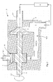
- FIG. 1 A first embodiment of a pump arrangement according to the invention 3 is shown in FIG.
- a shaft 5 is mounted about an axis of rotation 5.1, the first impeller 6 and a drive 8 for a Piston 9a receives.
- the first impeller 6 is considered to be radial compacting centrifugal impeller formed.
- the piston 9a forms a piston high pressure pump.
- This pump assembly 3 is for a closed circuit 1 is provided, which receives a filter element 12 and is circulated by the centrifugal pump 6, see Figure 8-11.
- a closed circuit 1 is within the meaning of the invention the direct connection of an input of the filter element 12 via the first impeller 6 with an output of To understand filter element 12. From the closed Circuit 1 can certainly branch off further circuits or other inflows and outflows may be provided.
- the pressure in the circuit 1 is up to 100 bar and is generated by the piston high-pressure pump 9. This is becoming filtering or through the reverse osmosis process to be cleaned salt or brackish water a cylinder chamber 10th the piston high-pressure pump 9 is supplied via an inlet 10.1. From the cylinder chamber 10, the fluid is via an outlet 10.2 and a line 10.3 fed into the circuit 1.
- the piston 9a of the high pressure piston pump 9 is by means of Nock 8 driven and is by a spring element 9.1 to Cam 8 biased towards.
- the inlet and outlet 10.1, 10.2 is controlled by a respective valve, which by a ball is shown symbolically.
- the outlet 10.2 When sucking fluid through the piston 9a, the outlet 10.2 is closed and the Inlet 10.1 open. During compression, the inlet becomes 10.1 closed and the outlet 10.2 open.
- the oscillating feed of the fluid has according to the invention on the continuously circulated via the centrifugal pump 6 Circuit 1 has no significant influence.
- the amount to fluid, which is fed via the high-pressure piston pump 9 becomes, in the form of retentate and pure water the circulation 1 in the flow direction behind the filter element 12th taken again see Figure 8-9.
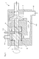
- the high-pressure piston pump 9 by a second impeller 7 is formed.
- the second impeller 7 is formed as a wellgelzellenrad.
- This invention Embodiment of a pump assembly 3 is still simpler in construction than the one described above.
- Inlet 10.1 and the outlet 10.2 are due to the continuous Pumping power of the diegelzellenrads 7 not through a valve closed.
- Both the high pressure stream as well the recirculation flow will be continuous without appreciable impulse fluctuations promoted.
- the pulse fluctuations due the drive of the shaft 5 are, depending on the embodiment if necessary to balance by a flywheel or similar measures.
- the rest of the construction corresponds to that of the pump arrangement 3 according to FIG. 1
- the embodiment according to FIG. 3 has opposite to FIG 1 shows a module for energy recovery according to FIG 9 on.
- a module for energy recovery according to FIG 9 on.
- an inlet 10.1 for the retentate provided via a second piston 9b is relaxed and discharged through an outlet 14.2.
- Inlet 14.1 branches in the flow direction in front of the first impeller 6 off.
- a spool 17 is provided, depending on the position of the second piston 9b the inlet 14.1 or the outlet 14.2 releases.
- the other structure corresponds to the embodiment according to FIG. 1
- the pump arrangement 3 according to FIG Pump assembly 3 of Figure 2 also a module for Recovery of the pressure energy of the retentate.
- the module or the third Impeller 14 is formed as diegelzellenrad.
- the third Impeller 14 for energy recovery is much easier constructed as the arrangement of the second piston 9b with the spool 17.
- the other structure of the pump assembly 3 corresponds to that in Figure 2 and with respect to the inlet 14.1 and the outlet 14.2 that of Figure 3.
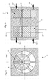
- FIGS. 5 to 7 show pressure-increasing modules, as in open circuits according to the figures 10 and 11 are used.
- the inventive feature that two rotating pumping elements arranged on a shaft 5 are preserved.
- the pressure booster module is used mainly the recovery of the high pressure level.
- the first impeller 6 and the second impeller 7 are as Vane pump wheels formed.
- the first impeller 6 does not serve as in the embodiments according to the figures 1 to 4 as a circulation pump, but as a module for energy recovery.
- FIG. 6 is a sectional view of a vane pump shown.
- FIG. 7 shows a pressure increase module according to the figures 5 and 6.
- the pressure booster module is equipped with a external motor driven. This can be used as a pump or formed based on any other principle be.
- the mass flows and their different Press to feed into circuit 1 and in Circuit 1 through the dimensioning of the individual pump elements to coordinate with each other.
- the invention thereby fixed parameters is an equal number of revolutions for all Pumping organs due to a shaft 5, the different Delivery volumes of the pumping organs the pressure conditions determine.
- pumps with the same volume flow or the same Volume per speed are for generating a high Pressure levels used, the different delivery volumes when using a two-part shaft 5 through different speeds are generated.
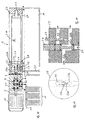
- FIGS. 12 to 14 show a solution for the entire osmosis plant, as for example for the production of drinking water Groundwater or brackish water in third world countries or for the treatment of seawater on pleasure boats and yachts is used.
- the housing 2 shown in Fig. 12 made of plastic formed of three sub-housings arranged side by side are.
- To the high pressure housing 2.1 includes the control housing 2.2 and the filter housing 2.3.
- the high pressure housing 2.1 takes the high-pressure piston pump 9 and is flanged together with the shaft 5 to a motor 13.
- On the opposite side of the engine 13 of the High-pressure housing 2.1 is the centrifugal impeller 6 of the centrifugal pump attached to the shaft 5.
- the membrane 12 is via a mounting flange 2.8 in the control housing 2.2 and a Mounting flange 2.9 fixed in the filter housing 2.3.
- the brackish or seawater to be treated is supplied via the inlet 1.1 and the mechanical pre-filter 11 of the high-pressure piston pump 9 supplied.
- the in a cylinder 9.2 is made of metal, the fluid via a hole 10.3 in the high-pressure housing 2.1 in the housing promoted the centrifugal pump 6, the same time Control housing 2.2 forms.
- Circulation 1 circulated which is necessary for the osmosis has high pressure level.
- the high pressure level is through the piston high-pressure pump 9 is shown.
- the fluid is starting from the inlet channel 2.2a together with the fluid from the High-pressure piston pump 9 through the centrifugal pump 6 in the outlet channel 2.2b promoted.
- the fluid flows into the main channel 2.10 of the filter housing 2.3, attached to the control housing 2.2 connects. From the main channel 2.10 from the fluid flows into the membrane 12. The filtered through the membrane 12 Fluid is called permeate and flows out of the membrane 12 via a removal channel 1.3 from the housing. 2
- the membrane 12 in the receiving flange 2.9 in the filter housing 2.3 stored, the corresponding hole having.
- the circulating and unfiltered fluid Increases concentration in this process can via a trained as a channel expiry 1.2 in the control box 2.2 are derived from the housing 2. For this is the procedure 1.2 via a pressure relief valve with a membrane channel 2.2c connected, the circuit 1 to inlet channel 2.2a closes.
- the membrane 12 can be rinsed after use, is below the housing 2 and der Membrane 12 a Spül matterser 18 arranged and the inlet channel 2.2 a via a Flushing 2.4 and a purge line 2.5 with the volume of Rinse tank 18 connected.
- the rinse tank 18 is at the beginning the osmosis process on the filter housing 2.3 with Permeate filled.
- the rinsing process makes this possible in the rinsing container 18 available permeate instead of highly concentrated Fluids or retentate in the circuit 1 through the membrane To pump 12 and then derive from the housing 2.
- control housing 2.2 and in Figs. 13 and 14 shown control housing are 2.2 not identical. Both have a control valve 2.6, the in the illustrated positions with the membrane channel 2.2c connects to the inlet channel 2.2a. In this position of the Control valve 2.6, it is possible to remove the retentate, is opened in the pressure relief valve 2.7.
- Fig. 13 shows a cross section of the control housing 2.2 according to Fig. 14.
- the operation and the geometry is essential to the invention and in FIGS. 13 and 14 for the Professional presented sufficiently extensive.
- the advantageous ones Dimensions, ratios and sealing measures serve at the same time to explain the operation.
Landscapes
- Engineering & Computer Science (AREA)
- Mechanical Engineering (AREA)
- General Engineering & Computer Science (AREA)
- Separation Using Semi-Permeable Membranes (AREA)
- Reciprocating Pumps (AREA)
- Details Of Reciprocating Pumps (AREA)
- Structures Of Non-Positive Displacement Pumps (AREA)
- Fluid-Driven Valves (AREA)
- Eye Examination Apparatus (AREA)
Abstract
Description
Die Erfindung bezieht sich auf eine Pumpenanordnung für ein Umkehrosmosesystem mit einem Pumpengehäuse und mit einem am Pumpengehäuse vorgesehenen Ansaugstutzen und Auslassstutzen.The invention relates to a pump arrangement for a Reverse osmosis system with a pump housing and with an am Pump housing provided intake manifold and outlet.
Es ist bereits eine Pumpenanordnung für ein Umkehrosmosesystem aus der WO 03 008 076 (HERRINGTON et al) bekannt. Dieses System umfasst als Druckmodul eine oszillierende Zweikolbenpumpe. Hierzu ist ein Differenzdruckventil den beiden Kolben zugeordnet, dass die Energierückgewinnung gewährleistet. Die Frequenz und die Amplitude der Zweikolbenpumpe sind maßgebend für die Druckwelle, die wiederum die Qualität des Permeats und des Durchsatzes sicherstellt.It is already a pump assembly for a reverse osmosis system from WO 03 008 076 (HERRINGTON et al). This system comprises an oscillating printing module Two piston pump. For this purpose, a differential pressure valve is the associated with both pistons that ensures energy recovery. Frequency and amplitude of the two-piston pump are decisive for the pressure wave, which in turn the Ensures quality of permeate and throughput.
Der Erfindung liegt die Aufgabe zugrunde, eine Pumpenanordnung derart auszubilden und anzuordnen, dass bei kleinen Masseströmen für die Umkehrosmose vorteilhafte Strömungsbedingungen einstellbar sind und die Pumpenanordnung billig herzustellen ist.The invention is based on the object, a pump assembly such form and arrange that with small Mass flow for the reverse osmosis advantageous flow conditions are adjustable and the pump assembly cheap is to produce.
Gelöst wird die Aufgabe erfindungsgemäß dadurch, dass die Pumpenanordnung eine Welle aufweist, wobei auf einem ersten Teil der Welle ein erstes Pumpenrad und auf einem zweiten Teil der Welle ein Antrieb für eine Kolbenhochdruckpumpe angeordnet ist.The object is achieved according to the invention that the Pump assembly having a shaft, wherein on a first Part of the shaft, a first impeller and on a second Part of the shaft is a drive for a high-pressure piston pump is arranged.
Hierdurch wird erreicht, dass über das erste Pumpenrad ein
Masse- bzw. Flüssigkeitsstrom mit hohem Druckniveau und mit
einer stetigen Geschwindigkeit gefördert wird und gleichzeitig
mit dem zweiten Pumpenrad oder mit dem Antrieb für
eine Kolbenhochdruckpumpe das hohe Druckniveau für die Umkehrosmose
einstellbar ist. Das erste den Masse- bzw. Flüssigkeitsstrom
bewegende Pumpenrad hat gegenüber einer
Kolbenpumpe den Vorteil, dass der Massestrom nicht
pulsierend gefördert wird und eine kritische Strömungsgeschwindigkeit
in der Membrane nicht unterschritten wird,
wie es bei Kolbenpumpen beim Ladungswechsel der Fall ist.
Das zweite Pumpenrad oder der Antrieb für die
Kolbenhochdruckpumpe ist erfindungsgemäß in dem gleichen
Pumpengehäuse wie das erste Pumpenrad angeordnet und wird
durch die gleiche rotierende Welle angetrieben wie das
erste Pumpenrad.
Die erfindungsgemäße Ausbildung ist aufgrund der einfachen
Steuerung ohne Druckdifferenzventil und der nahezu verschleißfreien
rotierenden Pumpen billiger und einfacher
aufgebaut.This ensures that via the first impeller a mass or liquid flow is conveyed at high pressure level and at a steady speed and simultaneously with the second impeller or with the drive for a high-pressure piston pump, the high pressure level for the reverse osmosis is adjustable. The first moving the mass or liquid flow impeller has the advantage over a piston pump that the mass flow is not pulsating promoted and a critical flow velocity in the membrane is not exceeded, as is the case with piston pumps during the charge cycle. The second impeller or the drive for the high-pressure piston pump according to the invention is arranged in the same pump housing as the first impeller and is driven by the same rotating shaft as the first impeller.
The inventive design is cheaper and simpler due to the simple control without pressure differential valve and the almost wear-free rotating pumps.
Vorteilhaft ist es hierzu auch, dass die Pumpenanordnung in einen offenen und/oder in einen geschlossenen Kreislauf für eine Flüssigkeit integriert ist. Dadurch wird erreicht, dass die erfindungsgemäße Pumpenanordnung gleichzeitig in verschiedene Anordnungen von Kreisläufen integrierbar ist. Dabei ist ein geschlossener Kreislauf mit einem oder mehreren offenen Kreisläufen kombinierbar, über die ein Massestrom zu- oder abgeführt wird.It is advantageous for this purpose that the pump assembly in an open and / or closed circuit for a liquid is integrated. This will achieve that the pump arrangement according to the invention simultaneously in various arrangements of circuits can be integrated. It is a closed circuit with one or more Combined open circuits, over which a mass flow is added or removed.
Eine diesbezügliche bevorzugte Möglichkeit ist gemäß einer Weiterbildung, dass die Pumpenanordnung ein System mit zumindest einem geschlossenen und zumindest einem offenen Kreislauf bildet. Im geschlossenen Kreislauf ist eine Membran eingebracht. Das Medium wird unter hohem für die Umkehrosmose notwendigem Druckniveau umgewälzt. Über einen offenen Kreislauf wird dem geschlossenen Kreislauf ständig ein Massestrom zugeführt, der an einer oder mehreren Stellen am geschlossenen Kreislauf wieder entnommen wird.A related preferred option is according to a Continuing that the pump assembly is a system with at least one closed and at least one open Cycle forms. In the closed circuit is a membrane brought in. The medium gets high for reverse osmosis necessary pressure level circulated. About one open circuit becomes the closed circuit constantly supplied to a mass flow at one or more locations is removed again at the closed circuit.
Ferner ist es vorteilhaft, dass der Ansaugstutzen und der Auslassstutzen dem ersten Pumpenrad zugeordnet sind und das erste Pumpenrad den Kreislauf schließt. Im geschlossenen Kreislauf wird somit die Flüssigkeit durch das erste Pumpenrad unter hohem Druckniveau umgewälzt. Dadurch wird erreicht, dass mit dem ersten Pumpenrad die Flüssigkeit im Kreislauf nur umgewälzt wird. Das erste Pumpenrad wird nicht zum Aufbringen des für die Umkehrosmose notwendigen hohen Druckniveaus eingesetzt.Furthermore, it is advantageous that the intake manifold and the Outlet are associated with the first impeller and the first impeller closes the circuit. In the closed Circulation thus becomes the fluid through the first impeller circulated under high pressure level. This will achieve that with the first impeller the liquid in Circulation is only circulated. The first impeller is not for applying the necessary for the reverse osmosis high pressure levels used.
Vorteilhaft ist es auch, dass der Kolbenhochdruckpumpe ein Einlass und ein Auslass zugeordnet ist, wobei der Auslass über eine Leitung mit dem Kreislauf in Verbindung steht. Über den Auslass wird dem Kreislauf kontinuierlich mit dem zweiten Pumpenrad oder mit der Kolbenhochdruckpumpe ein gewisser Massestrom an Flüssigkeit zugeführt, der an anderer Stelle des Kreislaufs wieder entnommen wird. Dieser Massestrom wird über den als Ansaugstutzen ausgebildeten Einlass zugeführt.It is also advantageous that the piston high-pressure pump a Inlet and an outlet is associated with the outlet communicates with the circuit via a line. About the outlet, the circuit is continuously with the second impeller or with the high-pressure piston pump a certain Mass flow of liquid supplied to the other Place the circuit is removed again. This mass flow is over the inlet designed as an intake fed.
Gemäß einer bevorzugten Ausführungsform der erfindungsgemäßen Lösung ist schließlich vorgesehen, dass das erste Pumpenrad als Niederdruckpumpe ausgebildet ist und am ersten Pumpenrad eine Druckdifferenz bis zu 7 bar einstellbar ist. Zum Umwälzen des Kreislaufs sind im Wesentlichen nur die Strömungs- und Reibungsverluste durch das erste Pumpenrad aufzubringen.According to a preferred embodiment of the invention Solution is finally provided that the first impeller is designed as a low pressure pump and the first Impeller a pressure difference up to 7 bar is adjustable. To circulate the circulation are essentially only the Flow and friction losses through the first impeller applied.
Von besonderer Bedeutung ist für die vorliegende Erfindung, dass das erste Pumpenrad als rotierende hydrodynamische oder hydrostatische Pumpe wie beispielsweise eine Kreiselpumpe, Impellerpumpe oder Flügelzellenpumpe ausgebildet ist. Prinzipiell sind alle rotierenden Pumpen einsetzbar, die einen annähernd kontinuierlichen Flüssigkeitsstrom ohne Ladungswechsel erzeugen.Of particular importance for the present invention, that the first impeller as a rotating hydrodynamic or hydrostatic pump such as a centrifugal pump, Impeller pump or vane pump formed is. In principle, all rotating pumps can be used, the an approximately continuous fluid flow without Generate charge change.
Im Zusammenhang mit der erfindungsgemäßen Ausbildung und Anordnung ist es von Vorteil, dass das zweite Pumpenrad als Kolbenhochdruckpumpe ausgebildet ist und am zweiten Pumpenrad oder an der Kolbenhochdruckpumpe eine Druckdifferenz bis zu 100 bar einstellbar ist. Dadurch wird erreicht, dass das für die Umkehrosmose erforderliche Druckniveau erzeugt wird und gleichzeitig ein Austausch von Flüssigkeiten ermöglicht wird, damit die Salzkonzentration im Kreislauf ein gewisses Maß nicht überschreitet.In connection with the embodiment of the invention and Arrangement, it is advantageous that the second impeller as Piston high-pressure pump is formed and the second impeller or at the high-pressure piston pump a pressure difference is adjustable up to 100 bar. This ensures that generates the required pressure level for the reverse osmosis and at the same time allows an exchange of liquids is, so that the salt concentration in the circulation does not exceed a certain level.
Vorteilhaft ist es ferner, dass das zweite Pumpenrad als rotierende hydrostatische Verdrängerpumpe wie beispielsweise eine Flügelzellenpumpe, Zahnradpumpe, Wälzkolbenpumpe oder Rotationskolbenpumpe ausgebildet ist. Prinzipiell sind alle rotierenden Pumpen einsetzbar, die ein entsprechendes Druckniveau erzeugen.It is also advantageous that the second pump as rotating hydrostatic positive displacement pump such as a vane pump, gear pump, Roots pump or rotary piston pump is formed. In principle, they are all rotating pumps can be used, which is a corresponding Generate pressure level.
Außerdem ist es vorteilhaft, dass die Kolbenhochdruckpumpe als oszillierende hydrostatische Verdrängerpumpe wie beispielsweise eine Kolbenpumpe oder eine Kolben-Hydromembranpumpe ausgebildet ist. Prinzipiell sind alle oszillierenden Pumpen einsetzbar, die ein entsprechendes Druckniveau erzeugen.It is also advantageous that the high-pressure piston pump as an oscillating hydrostatic positive displacement pump such as a piston pump or a piston hydraulic diaphragm pump is trained. In principle, all oscillating pumps can be used, which is a corresponding Generate pressure level.
Ferner ist es vorteilhaft, dass der zweite Teil der Welle als Nocke, gekröpft oder als Taumelscheibe als mittel- oder unmittelbarer Antrieb für zumindest einen in radialer Richtung zu einer Drehachse bewegbaren Kolben der Kolbenhochdruckpumpe ausgebildet ist. Dadurch wird erreicht, dass die zum Antrieb des ersten Pumpenrads vorgesehene Welle gleichzeitig eine oszillierende zweite Pumpe antreibt. In einem bevorzugten Ausführungsbeispiel ist der Antrieb als Nocke für einen Kolben ausgebildet.Furthermore, it is advantageous that the second part of the shaft as a cam, cranked or as a swash plate as medium or direct drive for at least one in the radial direction to a rotational axis movable piston of the high-pressure piston pump is trained. This ensures that the for driving the first impeller shaft provided simultaneously an oscillating second pump drives. In one preferred embodiment, the drive is a cam designed for a piston.
Um die Komplexität der erfindungsgemäßen Pumpenanordnung zu begrenzen, ist es von Vorteil, dass die Welle zumindest einteilig ausgebildet mit dem ersten Pumpenrad und mit dem Antrieb in dem Pumpengehäuse gelagert ist, wobei das Pumpengehäuse einteilig, verschraubt oder gegossen ausgebildet ist. Beide Pumpen sind somit unmittelbar nebeneinander in einem Pumpengehäuse angeordnet. Das Pumpengehäuse ist kompakt ausgebildet.To the complexity of the pump assembly according to the invention limit, it is advantageous that the wave at least integrally formed with the first impeller and with the Drive is mounted in the pump housing, wherein the pump housing formed in one piece, screwed or cast is. Both pumps are thus immediately adjacent to each other arranged a pump housing. The pump housing is compact educated.
Schließlich ist es von Vorteil, dass die Welle wenigstens zweiteilig ausgebildet ist und der erste Teil der Welle mit dem ersten Pumpenrad in einem ersten Gehäusekörper und der zweite Teil der Welle mit dem Antrieb in einem zweiten vom ersten Gehäusekörper baulich getrennten Gehäusekörper gelagert ist. Dadurch wird erreicht, dass die Wellen je nach Ausbildung der Pumpe hergestellt und erst beim Zusammenbau zumindest drehfest verbunden werden. In einem besonderen Ausführungsbeispiel ist vorgesehen, den ersten Teil und den zweiten Teil nicht innerhalb des Gehäuses zu verbinden. Dadurch wird erreicht, dass der erste Gehäusekörper hinsichtlich der unterschiedlichen Druckniveaus an dem den beiden Pumpen gegenüberliegenden zweiten Gehäusekörper angeschlossen ist. Die beiden Wellenteile sind über eine Zwischenwelle oder über einen Ketten- bzw. Riemenantrieb miteinander verbunden. Für eine solche externe Verbindung der beiden Wellenteile ist es von Vorteil, die beiden Wellenteile nicht in Flucht, sondern parallel zueinander anzuordnen, was einen Ketten- bzw. Riemenantrieb zum Einsatz bringt.After all, it is beneficial that the shaft at least is formed in two parts and the first part of the shaft with the first impeller in a first housing body and the second part of the shaft with the drive in a second from stored first housing body structurally separate housing body is. This will cause the waves to move according to Training the pump made and only during assembly be connected at least rotatably. In a special Embodiment is provided, the first part and the second part does not connect inside the case. Thereby is achieved that the first housing body in terms the different pressure levels at the two Pumps opposite second housing body connected is. The two shaft parts are via an intermediate shaft or via a chain or belt drive with each other connected. For such an external connection of the two Shaft parts, it is advantageous, the two shaft parts not in flight but in parallel to each other, what brings a chain or belt drive used.
Vorteilhaft ist es hierzu auch, dass der dem Antrieb auf dem zweiten Teil der Welle zugeordnete Kolben in einem Zylinderraum im Pumpengehäuse oder im zweiten Gehäusekörper gelagert ist und dem Zylinderraum der Einlass und der Auslass zugeordnet ist, wobei der Auslass über eine Leitung mit dem Kreislauf in Verbindung steht. Dadurch wird erreicht, dass eine oszillierende und den Hochdruck aufbauende Pumpe über den Auslass in den Kreislauf integriert ist und über den Einlass eine Zuführung für noch zu filternde Flüssigkeit gebildet ist.It is also advantageous for this that the drive on the second part of the shaft associated piston in a cylinder chamber in the pump housing or in the second housing body is stored and the cylinder chamber, the inlet and the outlet is assigned, the outlet via a line connected with the circulation. This will achieve that an oscillating and the high pressure building up Pump is integrated into the circuit via the outlet and via the inlet a feeder for still to be filtered Liquid is formed.
Letztlich ist es von Vorteil, dass das zweite Pumpenrad auf der Welle in einem Pumpenraum gelagert ist und dem Pumpenraum der Einlass und der Auslass zugeordnet ist, wobei der Auslass über eine Leitung mit dem Kreislauf in Verbindung steht. Dadurch wird gegenüber der vorstehend beschriebenen oszillierenden Pumpe eine rotierende, den Hochdruck aufbauende Pumpe über den Auslass in den Kreislauf integriert. Über den Einlass ist eine Zuführung für noch zu filternde Flüssigkeit gebildet.Ultimately, it is an advantage that the second impeller is on the shaft is stored in a pump room and the pump room the inlet and the outlet is assigned, wherein the Outlet connected via a line to the circuit stands. This is compared with the above oscillating pump a rotating, building up the high pressure Pump integrated into the circuit via the outlet. Over the inlet is a feeder for still to be filtered Liquid formed.
Vorteilhaft ist es hierzu auch, dass dem Kreislauf mitteloder unmittelbar ein Zulauf, ein Ablauf und ein Entnahmestutzen zugeordnet ist. Durch den Zulauf wird ein gewisser Massestrom noch zu filternder Flüssigkeit aufgenommen. Dieser Massestrom entspricht der Summe des am Ablauf und am Entnahmestutzen abgeführten Massestroms. Am Entnahmestutzen wird gefilterte bzw. aufbereitete Flüssigkeit entnommen, wohingegen am Ablauf Konzentrat abfließt.It is also advantageous for this purpose that the circuit medium or directly an inlet, a drain and a withdrawal nozzle assigned. By the inlet is a certain Mass flow of liquid still to be filtered added. This Mass flow corresponds to the sum of the expiration and the Outlet neck discharged mass flow. At the withdrawal nozzle if filtered or treated liquid is removed, whereas concentrate drains off at the drain.
Eine zusätzliche Möglichkeit ist gemäß einer Weiterbildung, dass der Einlass als Zulauf ausgebildet ist. Dadurch wird ein einfacher Aufbau erreicht.An additional possibility is according to a development, that the inlet is designed as an inlet. This will achieved a simple structure.
Ferner ist es vorteilhaft, dass im offenen Kreislauf der Auslass des zweiten Pumpenrades oder der Auslass der Kolbenhochdruckpumpe unmittelbar über den Kreislauf mit dem Ansaugstutzen des ersten Pumpenrades in Verbindung steht. Dadurch wird erreicht, dass das erste Pumpenrad hydraulisch mit dem zweiten Pumpenrad oder mit der Kolbenhochdruckpumpe gekoppelt ist. Der im offenen Kreislauf abzuführende und nicht gefilterte Massestrom mit hohem Druckniveau wird somit als hydraulischer Motor zum Antreiben des Hochdruckelements eingesetzt.Furthermore, it is advantageous that in the open circuit of Outlet of the second impeller or the outlet of the high-pressure piston pump immediately across the circuit with the Inlet of the first impeller is in communication. This ensures that the first impeller hydraulically with the second impeller or with the high-pressure piston pump is coupled. The discharged in the open circuit and Unfiltered mass flow with high pressure level is thus as a hydraulic motor for driving the high pressure element used.
Vorteilhaft ist es auch, dass der Auslass als Ablauf ausgebildet ist und/oder das zweite Pumpenrad oder das erste Pumpenrad als Hydromotor einsetzbar ist. Dadurch wird erreicht, dass das hohe Druckniveau auf verschiedenste Weisen genutzt wird, um das Hochdruckelement anzutreiben.It is also advantageous that the outlet is designed as a drain is and / or the second impeller or the first Impeller can be used as a hydraulic motor. This will achieve that the high pressure level in various ways is used to drive the high-pressure element.
Gemäß einer bevorzugten Ausführungsform der erfindungsgemäßen Lösung ist schließlich vorgesehen, dass der Welle ein drittes Pumpenrad oder ein zweiter Kolben und dem Pumpenrad oder dem zweiten Kolben ein Einlass und ein Auslass am Pumpengehäuse oder am Gehäusekörper zugeordnet ist, wobei der Ablauf des Kreislaufs mit dem Einlass verbunden ist und/oder das Pumpenrad oder der zweite Kolben als Hydromotor einsetzbar ist. Dadurch wird erreicht, dass das Umwälzen der Flüssigkeit getrennt vom Einspeisen der Flüssigkeit und getrennt von der Rückgewinnung der Druckenergie über jeweils eine Pumpe erfolgt. Hierbei werden die für die jeweilige Aufgabe speziellen Eigenschaften der einsetzbaren Pumpen ausgenutzt und ein einfacher Aufbau der Pumpenanordnung erreicht.According to a preferred embodiment of the invention Solution is finally provided that the shaft third impeller or a second piston and impeller or the second piston an inlet and an outlet on the pump housing or is assigned to the housing body, wherein the Drain of the circuit is connected to the inlet and / or the impeller or the second piston as a hydraulic motor can be used. This ensures that the circulation the liquid separated from the feeding of the liquid and separated from the recovery of the pressure energy one pump each. Here are the for each Task special properties of usable Pump used and a simple construction of the pump assembly reached.
Von besonderer Bedeutung ist für die vorliegende Erfindung, dass das erste Pumpenrad und das zweite Pumpenrad als Flügelzellenrotor oder rotierende Verdrängerpumpe ausgebildet sind, wobei der dem zweiten Pumpenrad zugeordnete Auslassstutzen und der dem ersten Pumpenrad zugeordnete Ansaugstutzen über den offenen Kreislauf verbunden sind und der Auslassstutzen des ersten Pumpenrads über ein offenes Volumen einer Flüssigkeit mit dem Einlass des zweiten Pumpenrads verbunden ist. Dadurch wird ein Druckerhöhungsmodul gebildet, das auch ohne Ventile funktioniert.Of particular importance for the present invention, that the first impeller and the second impeller as vane rotor or rotating positive displacement pump formed are, wherein the second impeller associated with the outlet nozzle and the intake manifold associated with the first impeller connected via the open circuit and the Outlet of the first impeller over an open volume a liquid with the inlet of the second impeller connected is. This will be a booster module formed, which works without valves.
Im Zusammenhang mit der erfindungsgemäßen Ausbildung und Anordnung ist es von Vorteil, dass zumindest eine Welle mittel- oder unmittelbar manuell und/oder über einen Elektro- und/oder über einen Verbrennungsmotor antreibbar ist. Dadurch ist das Druckerhöhungsmodul mit jedem beliebigen Motor kombinierbar. In Extremsituationen ist auch eine Dampfmaschine als Motor einsetzbar. Die erforderliche Drehzahl der Pumpenwelle wird über ein einfaches Stirnradgetriebe zwischen Motor und Pumpenwelle modifiziert.In connection with the embodiment of the invention and Arrangement, it is advantageous that at least one shaft directly or indirectly and / or via an electrical and / or driven by an internal combustion engine is. This makes the booster module with any one Motor can be combined. In extreme situations is also one Steam engine can be used as a motor. The required speed the pump shaft is via a simple spur gear modified between engine and pump shaft.
Vorteilhaft ist es ferner, dass der Einlass von zumindest einem Pumpenrad hydraulisch mit einer externen Pumpe oder einer Druckleitung verbunden ist und das Pumpenrad über die externe Pumpe oder die Druckleitung hydraulisch antreibbar ist. Dadurch wird eine Alternative zum Antrieb über eine drehende Welle geschaffen. Neben dem Hochdruck- und Umwälzmodul ist ein drittes Pumpenelement der Welle zugeordnet. Das dritte Pumpenelement ist an einen bestehenden Pumpenkreislauf anzuschließen, über den der Antrieb der Pumpenanordnung erfolgt. Beispielsweise ist das dritte Pumpenrad über den Kühlwasserkreislauf eines Schiffsmotors antreibbar.It is also advantageous that the inlet of at least a pump impeller hydraulically with an external pump or a pressure line is connected and the impeller via the external pump or the pressure line hydraulically driven is. This will be an alternative to the drive via a created rotating shaft. In addition to the high pressure and circulation module a third pump element is assigned to the shaft. The third pump element is connected to an existing pump circuit connect, via which the drive of the pump assembly he follows. For example, the third impeller drivable via the cooling water circuit of a marine engine.
Hierzu ist es vorteilhaft, dass der förderbare Volumenstrom des zweiten Pumpenrades größer oder unterschiedlich dem förderbaren Volumenstrom des ersten Pumpenrades ist und dieser Differenzvolumenstrom zwischen 80 und 100 % dem am Entnahmestutzen entnehmbaren Volumenstrom entspricht. Dadurch wird erfindungsgemäß erreicht, dass ein über die beiden Pumpen verbundenes Filtersystem von einem niedrigen Druckniveau zu Beginn auf ein hohes Druckniveau gebracht werden kann, obwohl das zweite Pumprad über eine externe Pumpe mit niedrigen Druckniveau angetrieben wird. Das erste Pumprad ist über eine Welle mit dem zweiten Pumprad verbunden und bildet einen Hydromotor. Dieses System ermöglicht die Einstellung eines hohen Druckniveaus ohne Hochdruckpumpe.For this purpose, it is advantageous that the deliverable volume flow of the second impeller greater than or different than the can be conveyed volume flow of the first impeller and this difference volume flow between 80 and 100% of the am Removal nozzle corresponds to removable flow. Thereby is achieved according to the invention that one over the two Pump connected filter system from a low Pressure level initially brought to a high pressure level can be, although the second pump wheel via an external Pump is driven at low pressure level. The first Pump wheel is connected via a shaft with the second pump and forms a hydraulic motor. This system allows the setting of a high pressure level without high-pressure pump.
Außerdem ist es vorteilhaft, dass zumindest ein Teil zumindest eines Gehäuses und/oder eines Bauteils der erfindungsgemäßen Anordnung aus chemisch beständigem Material wie beispielsweise salzwasserbeständigem Stahl, salzwasserbeständiger Bronze und/oder Kunststoff ausgebildet ist. Als Stahl ist beispielsweise V4A® oder AISI316® einsetzbar.Moreover, it is advantageous that at least one part at least a housing and / or a component of the invention Arrangement of chemically resistant material such as For example, saltwater resistant steel, saltwater resistant Bronze and / or plastic is formed. When Steel can be used for example V4A® or AISI316®.
Ferner ist es vorteilhaft, dass zumindest ein Teil zumindest eines Gehäuses und/oder eines Bauteils der erfindungsgemäßen Anordnung beschichtet ist. Dadurch wird erreicht, dass die Pumpenanordnung unabhängig vom Grundmaterial seewasserbeständig ist.Furthermore, it is advantageous that at least one part at least a housing and / or a component of the invention Arrangement is coated. This will achieve that the pump assembly is seawater resistant, regardless of the base material is.
Hierzu ist es vorteilhaft, dass zumindest ein Teil zumindest eines Gehäuses und/oder eines Bauteils der erfindungsgemäßen Anordnung beispielsweise durch elektrolytische Oxidation, durch chemisches Auftragen oder durch elektrolytisch aufgebrachtes Metall beschichtet ist. Hierzu wird beispielsweise Nickel chemisch aufgetragen oder eine elektrolytische Beschichtung aus Chrom, Nickel, Silber oder Gold gebildet.For this purpose, it is advantageous that at least one part at least a housing and / or a component of the invention Arrangement for example by electrolytic oxidation, by chemical application or by electrolytic coated metal is coated. For this purpose is For example, nickel chemically applied or an electrolytic Coating of chrome, nickel, silver or gold educated.
Schließlich ist es von Vorteil, dass zumindest ein Teil zumindest eines Gehäuses und/oder eines Bauteils der erfindungsgemäßen Anordnung mit einer die tribologischen Eigenschaften verbessernden Schicht beschichtet ist. Dadurch wird erreicht, dass die Reibung, der Verschleiß und die Schmierung optimiert und dadurch Energie eingespart wird.Finally, it is advantageous that at least a part at least a housing and / or a component of the invention Arrangement with one of the tribological properties is coated with improving layer. Thereby is achieved that the friction, the wear and the Optimized lubrication and thereby energy is saved.
Vorteilhaft ist es hierzu auch, dass zumindest ein Teil des Zylinderraums oder eines metallischen Bauteils chemisch mit Nickel und mit einer Einlagerung aus Teflon® beschichtet ist. Dadurch wird erreicht, dass als Gehäusematerial Aluminium einsetzbar ist und die Kolbenhochdruckpumpe sehr einfach für Drücke bis über 60 bar auslegbar ist.It is also advantageous for this that at least a part of the Cylinder space or a metallic component with chemically Nickel and coated with Teflon® is. This ensures that the housing material is aluminum can be used and the piston high pressure pump very simple for pressures up to more than 60 bar can be interpreted.
Letztlich ist es von Vorteil, dass zumindest ein Teil eines Kunststoffbauteils galvanisch und/oder chemisch mit einer metallischen Schicht beschichtet ist.Ultimately it is an advantage that at least a part of a Plastic component galvanically and / or chemically with a coated metallic layer.
Prinzipiell erhalten die verschiedensten Grundmaterialien ihre erfindungsgemäße Beständigkeit erst durch Beschichtungsverfahren, die zu den verschiedenen vorstehend genannten Beschichtungen führen. Hierzu ist das Verfahren zum Beschichten eines Bauteils aus einer Aluminiumlegierung oder eines Bauteils aus Kunststoff durch chemische Vernicklung mit einer Einlagerung aus Teflon® besonders vorteilhaft.In principle, the most diverse basic materials are obtained their resistance according to the invention only by coating methods, those to the various above mentioned Coatings lead. This is the process for coating a component made of an aluminum alloy or a plastic component by chemical nickel plating with a storage of Teflon® particularly advantageous.
Vorteilhaft ist es auch, dass das System bestehend aus der erfindungsgemäßen Pumpenanordnung mit zumindest einem Kreislauf und zumindest einem im Flüssigkeitskreislauf integrierten Filterelement kombiniert ist.It is also advantageous that the system consisting of the Pump assembly according to the invention with at least one Circuit and at least one integrated in the fluid circuit Filter element is combined.
Eine zusätzliche Möglichkeit ist gemäß einer Weiterbildung, dass im Kreislauf zumindest ein Filterelement oder mehrere Filterelemente in Reihe oder parallel angeordnet sind.An additional possibility is according to a development, that in the circuit at least one filter element or more Filter elements are arranged in series or in parallel.
Ferner ist es vorteilhaft, dass das Filterelement als Filter oder als Membrane ausgebildet ist. Die Membrane ermöglicht den Einsatz für die Umkehrosmose. Furthermore, it is advantageous that the filter element as a filter or is designed as a membrane. The membrane allows the use for reverse osmosis.
Vorteilhaft ist es auch, dass das System zur Umkehrosmose und zur Wasseraufbereitung einsetzbar ist. Das entsprechend hohe Druckniveau wird durch die erfindungsgemäße Ausbildung der Pumpen und der Antriebe erreicht.It is also advantageous that the system for reverse osmosis and can be used for water treatment. The corresponding high pressure level is due to the inventive design reached the pumps and drives.
Gemäß einer bevorzugten Ausführungsform der erfindungsgemäßen Lösung ist schließlich vorgesehen, dass die Förderleistung am Entnahmestutzen zwischen 1 und 50 Liter pro Stunde, im Besonderen zwischen 5 und 20 Liter pro Stunde beträgt.According to a preferred embodiment of the invention Solution is finally provided that the delivery rate at the sampling nozzle between 1 and 50 liters per hour, in particular between 5 and 20 liters per hour.
Die Erfindung bezieht sich ebenso auf eine Umkehrosmoseanlage mit mindestens zwei in einem Gehäuse gelagerten Pumpen, einem Kreislauf in den eine der beiden Pumpen integriert sind und mindestens einer in den Kreislauf integrierten Membrane, wobei ein Steuerventil vorgesehen ist.The invention also relates to a reverse osmosis system with at least two pumps mounted in a housing, a circuit integrated into the one of the two pumps and at least one integrated into the cycle Diaphragm, wherein a control valve is provided.
Gelöst wird die Aufgabe Dadurch, dass zusätzlich zu den beiden Pumpen, das Steuerventil und die Membrane in einem ein- oder mehrteiligen Gehäuse angeordnet sind.The task is solved by the fact that in addition to the Both pumps, the control valve and the membrane in one one or more parts housing are arranged.
Dadurch wird erreicht, dass keine Schläuche oder Rohre als Leitungen vorzusehen sind, da alle Leitungen durch Bohrungen und Ausnehmungen im Gehäuse gebildet sind. Die Anlage kann dadurch äußerst kompakt gebaut werden.This ensures that no hoses or pipes than Lines are to be provided, as all lines through holes and recesses are formed in the housing. The attachment This makes it extremely compact.
Hierzu ist es vorteilhaft, dass das Gehäuse ein Hochdruckgehäuse, ein Steuergehäuse und ein Filtergehäuse aufweist, wobei im Hochdruckgehäuse die Welle und die Kolbenhochdruckpumpe, im Steuergehäuse das Steuerventil und im Filtergehäuse die Membrane angeordnet bzw. gelagert sind. Die drei Teilgehäuse können mit Hilfe von Klemmen oder Bolzen zu einem Gehäuse zusammengesetzt werden. For this purpose, it is advantageous for the housing to be a high-pressure housing, a control housing and a filter housing, wherein in the high-pressure housing, the shaft and the high-pressure piston pump, in the control housing, the control valve and in the filter housing the membrane are arranged or stored. The Three sub-housings can be made with the help of clamps or bolts be assembled into a housing.
Hinsichtlich der Umkehrosmose von Salzwasser ist es vorteilhaft, dass das Gehäuse aus einem seewasserbeständigen Kunststoff oder Metall gebildet und das Gehäuse und die Welle an einen Motor (13) anflanschbar sind. Kunststoff läst sich mechanisch sehr einfach bearbeiten und weist hinsichtlich des erforderlichen Drucks ein ausreichend hohes Elastizitätsmodul auf.With regard to the reverse osmosis of salt water, it is advantageous that the housing is made of a seawater resistant Plastic or metal formed and the housing and the Shaft to a motor (13) are flanged. plastic can be mechanically very easy to handle and points in terms the required pressure a sufficiently high Elastic modulus on.
Es ist vorteilhaft, dass die Kolbenhochdruckpumpe einen Zylinder aufweist und der Zylinder in das Gehäuse eingesetzt ist. Der Zylinder ist aus einem verschleißfesten Metall oder aus Keramik. Wie eingangs beschrieben, kann die Lauffläche für den Kolben beschichtet sein.It is advantageous that the high-pressure piston pump has a cylinder and the cylinder is inserted into the housing is. The cylinder is made of a wear-resistant metal or made of ceramic. As described above, the tread be coated for the piston.
Es ist vorteilhaft, dass das Hochdruckgehäuse eine Bohrung aufweist, die die Kolbenhochdruckpumpe mit der Kreiselpumpe verbindet. Je kürzer diese Verbindung ist, desto effizienter arbeitet das System.It is advantageous that the high pressure housing has a bore having the high-pressure piston pump with the centrifugal pump combines. The shorter this connection, the more efficient the system works.
Ferner ist es vorteilhaft, dass das Kreiselpumpenrad auf der Welle befestigt und zwischen dem Hochdruckgehäuse und dem Steuergehäuse angeordnet ist. Das eigentliche Pumpengehäuse für das Kreiselpumpenrad ist im Steuergehäuse vorgesehen.Furthermore, it is advantageous that the Kreiselpumpenrad on attached to the shaft and between the high pressure housing and is arranged the control housing. The actual pump housing for the centrifugal impeller is provided in the control housing.
Hinsichtlich eines einfachen Aufbaus ist es vorteilhaft,
dass das Steuergehäuse
Hierzu ist es vorteilhaft, dass an den Spülkanal eine Spülleitung anschließt und die Spülleitung den Spülkanal mit einem Spülbehälter verbindet. Diese Ausgestaltung vereinfacht die Pflege der Membrane die nach Gebrauch gespült werden sollte.For this purpose, it is advantageous that a flushing line to the flushing channel connects and the flushing line with the flushing channel a rinsing container connects. This embodiment is simplified Care of the membrane, which is rinsed after use should be.
Ferner ist es vorteilhaft, dass die Membrane zylindrisch
ausgebildet ist und das Filtergehäuse
Es ist vorteilhaft, dass das Steuergehäuse zumindest fünf
Bohrungen aufweist, die jeweils einen Kanal bilden, wobei
Ergänzend ist es vorteilhaft, dass im Steuergehäuse ein Steuerventil vorgesehen ist, dass in einer ersten Position den Ablauf gegenüber dem Spülkanal verschließt und in einer zweiten Position den Membrankanal gegenüber dem Einlasskanal verschließt. In der ersten Position kann das Steuergehäuse nur in einem Kanal durchströmt werden. In der zweiten Position hingegen in zwei Kanälen.In addition, it is advantageous that in the control housing a Control valve is provided that in a first position closes the drain opposite the flushing channel and in one second position the membrane channel opposite the inlet channel closes. In the first position, the control housing only be flowed through in a channel. In the second Position, however, in two channels.
Es ist vorteilhaft, dass im Steuergehäuse ein Überdruckventil vorgehen ist, über das der Überdruckkanal geregelt verschließbar ist. Das Überdruckventil ist elektromagnetisch oder manuell steuerbar.It is advantageous that in the control housing, a pressure relief valve Proceed is over which the overpressure channel controlled closed is. The pressure relief valve is electromagnetic or manually controllable.
Mit dieser Vorrichtung kann ein Verfahren betrieben werden,
bei dem
Hierzu ist es vorteilhaft, dass das Permeat aus dem Spülbehälter durch den Spülkanal angesaugt und über den Einlasskanal der Membrane zugeführt und anschließend von der Membrane über den Membrankanal und den Ablauf abgeführt wird. Das Permeat durchströmt dabei die Membrane in der Das Permeat durchströmt dabei die Membrane in der gleichen Richtung wie bei dem gewinnen von Trinkwasser.For this purpose, it is advantageous that the permeate from the Suction container sucked through the flushing channel and over the Inlet of the membrane supplied and then from Membrane via a membrane channel and an outlet are removed becomes. The permeate flows through the membrane in the The permeate flows through the membrane in the same Direction as in winning drinking water.
Weitere Vorteile und Einzelheiten der Erfindung sind in den Patentansprüchen und in der Beschreibung erläutert und in den Figuren dargestellt. Es zeigt:
Figur 1- eine schematische Schnittansicht einer Pumpenanordnung bestehend aus einer Hochdruck-Kolbenpumpe und einer Umwälz-Kreiselpumpe;
Figur 2- eine schematische Schnittansicht einer Pumpenanordnung bestehend aus einer HochdruckFlügelzellenpumpe und einer Umwälz-Kreiselpumpe;
Figur 3- eine schematische Schnittansicht einer Pumpenanordnung bestehend aus einer Hochdruck-Kolbenpumpe, einer Kolbenpumpe als Hydromotor und einer Umwälz-Kreiselpumpe;
Figur 4- eine schematische Schnittansicht einer Pumpenanordnung bestehend aus einer Hochdruck-Flügelzellenpumpe, einer Flügelzellenpumpe als Hydromotor und einer Umwälz-Kreiselpumpe;
Figur 5- ein Druckerhöhungsmodul mit zwei Flügelzellenpumpen und einer Schnittführung A-A';
Figur 6- eine Schnittansicht der Flügelzellenpumpe gemäß Figur 5;
Figur 7- ein Druckerhöhungsmodul mit eigenem Antrieb;
Figur 8- einen geschlossenen Kreislauf ohne Energierückgewinnung;
Figur 9- einen geschlossenen Kreislauf mit Energierückgewinnung;
Figur 10- einen offenen Kreislauf mit eigenem Antrieb;
- Figur 11
- einen offenen Kreislauf mit einem Antrieb über Fremddruck;
Figur 12- einen Querschnitt eines Gesamtsystems mit einem dreiteiligen Gehäuse;
Figur 13- einen Querschnitt eines Steuergehäuses;
Figur 14- einen gegenüber Fig. 13 um 90° gedrehten Querschnitt des Steuergehäuses.
- FIG. 1
- a schematic sectional view of a pump assembly consisting of a high-pressure piston pump and a circulating centrifugal pump;
- FIG. 2
- a schematic sectional view of a pump assembly consisting of a high pressure paddle pump and a circulating centrifugal pump;
- FIG. 3
- a schematic sectional view of a pump assembly consisting of a high-pressure piston pump, a piston pump as a hydraulic motor and a circulating centrifugal pump;
- FIG. 4
- a schematic sectional view of a pump assembly consisting of a high-pressure vane pump, a vane pump as a hydraulic motor and a circulating centrifugal pump;
- FIG. 5
- a pressure increase module with two vane pumps and a cutting guide A-A ';
- FIG. 6
- a sectional view of the vane pump according to Figure 5;
- FIG. 7
- a pressure booster module with its own drive;
- FIG. 8
- a closed cycle without energy recovery;
- FIG. 9
- a closed cycle with energy recovery;
- FIG. 10
- an open circuit with its own drive;
- FIG. 11
- an open circuit with a drive via external pressure;
- FIG. 12
- a cross-section of an overall system with a three-part housing;
- FIG. 13
- a cross section of a control housing;
- FIG. 14
- a comparison with FIG. 13 rotated by 90 ° cross-section of the control housing.
In den Figuren 1 bis 7 sind verschiedene Varianten von
erfindungsgemäßen Pumpenanordnungen 3 dargestellt, die für
die in den Figuren 8 bis 11 dargestellten Wirkungsprinzipien
einsetzbar sind.FIGS. 1 to 7 show different variants of
Die Wirkungsprinzipien sind nach Art eines Kreislaufs 1,
nämlich in geschlossene Kreisläufe 1 gemäß den Figuren 8
und 9 sowie in offene Kreisläufe 1 gemäß den Figuren 10 und
11 zu unterscheiden. Bei den geschlossenen Kreisläufen 1
ist ein Filterelement 12 in einen Kreislauf 1 eingebunden,
der über ein erstes Pumpenrad 6 umgewälzt wird. Das erste
Pumpenrad 6 ist als Kreiselpumpe oder Flügelzellenpumpe
ausgebildet. Das flüssige Medium in diesem Kreislauf 1
steht je nach Art des Mediums unter einem Druck von 5 bis
100 bar. Das Medium ist bezüglich eines bevorzugten Ausführungsbeispiels
Brackwasser oder Meer beziehungsweise Salzwasser.
Der Druck von 5 bis 100 bar wird durch ein zweites
Pumpenrad 7 erzeugt. The principles of action are in the manner of a
Dem Kreislauf 1 wird stetig über einen Zulauf 1.1 ein Volumenstrom
an Brack- oder Meerwasser aus einem offenen Volumen
15 über das zweite Pumpenrad 7 zugeführt. Der gleiche
Volumenstrom wird in der Summe an einem Ablauf 1.2 und an
einem Entnahmestutzen 1.3 des Kreislaufs 1 entnommen. Hierzu
wird über den Entnahmestutzen 1.3 an dem Filterelement
12 Reinwasser und an dem Ablauf 1.2 Retentat beziehungsweise
aufkonzentriertes Brack- beziehungsweise Meerwasser
entnommen.The
Am Entnahmestutzen 1.3 ist ein Überstrom- oder Druckhalteventil
1.4 vorgesehen. Das zweite Pumpenrad 7 ist zur Erzeugung
des hohen Druckniveaus als Flügelzellenpumpe oder
als Kolbenpumpe ausgebildet. Erfindungsgemäß sind beide
Pumpenräder 6, 7 über eine Welle 5 verbunden und werden über
die Welle 5 durch einen Motor 13 angetrieben.At the sampling port 1.3 is an overcurrent or pressure relief valve
1.4 provided. The
Die Darstellung gemäß Figur 9 zeigt neben dem vorstehend
beschriebenen Aufbau eine Möglichkeit der Energierückgewinnung.
Hierzu wird die Druckenergie des am Ablauf 1.2 entnommenen
Retentats über ein drittes Pumpenrad 14 dem Antriebsstrang
zugeführt. Im Pumpenrad 14 wird das Retentat
von dem hohen Druckniveau auf Umgebungsdruck entspannt.The illustration according to FIG. 9 shows, in addition to the above
described structure a way of energy recovery.
For this purpose, the pressure energy of the extracted 1.2 at the outlet
Retentats via a
Gemäß den Figuren 10 und 11 ist ein offener Kreislauf 1
dargestellt. Im offenen Kreislauf 1 ist das Filterelement
12 eingangs- und ausgangsseitig über jeweils ein erstes
Pumpenrad 6 und ein zweites Pumpenrad 7 mit einem offenen
Volumen 15 verbunden. Dem offenen Kreislauf 1 wird gegenüber
dem geschlossenen lediglich am Entnahmestutzen 1.3
in Strömungsrichtung hinter dem Filterelement 12 Reinwasser
entnommen. Der über den Zulauf 1.1 eingebrachte Volumenstrom
an Brack- oder Meerwasser wird somit bis auf den
Reinwasser-Volumenstrom über den Ablauf 1.2 wieder dem offenen
Volumen 15 zugeführt.According to FIGS. 10 and 11, an open circuit is 1
shown. In
Nach dem Ausführungsbeispiel gemäß Figur 10 werden die beiden
Pumpenräder 6, 7 über eine Welle 5 und einen an der
Welle 5 angeordneten Motor 13 angetrieben. Durch die erfindungsgemäße
Verbindung der beiden Pumpenräder 6, 7 über eine
Welle 5 ist die Energierückgewinnung des hohen Druckniveaus
gewährleistet. Abgesehen von den Strömungs- und Reibungsverlusten
ist bei dieser Anordnung nur der Energiebetrag
aufzubringen, der durch die Entnahme von Reinwasser am
Entnahmestutzen 1.3 verloren geht.According to the embodiment of Figure 10, the two
Das Ausführungsbeispiel gemäß Figur 11 zeigt einen Antrieb
durch Fremddruck. Die Pumpenanordnung 3 ist erfindungsgemäß
an eine beliebige externe Pumpe 16 mit Motor 13 angeschlossen.
Das niedrige Druckniveau der externen Pumpe 16 reicht
erfindungsgemäß zumindest aus um Reibungs- und Strömungsverluste
im System zu überwinden. Das erforderliche hohe
Druckniveau im System entsteht durch die als Hydromotor arbeitende
und über die Welle 5 mit der zweiten Pumpe 7 verbundene
erste Pumpe 6. Das hohe Druckniveau entsteht durch
die unterschiedlichen Fördervolumina bei gleicher Drehzahl
der beiden Pumpen 6, 7. Erfindungsgemäß gilt, dass der Volumenstrom
der Pumpe 7 beziehungsweise des zweiten Pumprades
7 dem Volumenstrom der externen Pumpe 16 entspricht.
Der Volumenstrom der externen Pumpe 16 wiederum entspricht
der Summe des Volumenstroms der Pumpe 6 beziehungsweise des
ersten Pumprades und dem Volumenstrom am Entnahmestutzen
1.3. Dadurch ist gewährleistet, dass der Druck im System
steigt, solange der Entnahmestutzen 1.3 geschlossen
ist. Die Volumenströme lassen sich wie folgt darstellen:
Bei der Volumenstrombilanz ist das Volumen an entnommenen oder gefilterten Schmutzpartikeln sowie Verluste durch Leckagen zu berücksichtigen.In the volumetric flow balance, the volume is taken from or filtered dirt particles as well as losses due to leaks to take into account.
Ein erstes Ausführungsbeispiel einer erfindungsgemäßen Pumpenanordnung
3 ist in Figur 1 dargestellt. In einem Pumpengehäuse
4 ist eine Welle 5 um eine Drehachse 5.1 gelagert,
die das erste Pumpenrad 6 und einen Antrieb 8 für einen
Kolben 9a aufnimmt. Das erste Pumpenrad 6 ist als radial
verdichtendes Kreiselpumpenrad ausgebildet. Der Kolben 9a
bildet eine Kolbenhochdruckpumpe 9.A first embodiment of a pump arrangement according to the
Diese Pumpenanordnung 3 ist für einen geschlossenen Kreislauf
1 vorgesehen, der ein Filterelement 12 aufnimmt und
durch die Kreiselpumpe 6 umgewälzt wird, siehe Figur 8-11.
Bei einem geschlossenen Kreislauf 1 ist im Sinne der Erfindung
die direkte Verbindung eines Eingangs des Filterelements
12 über das erste Pumpenrad 6 mit einem Ausgang des
Filterelements 12 zu verstehen. Von dem geschlossenen
Kreislauf 1 können durchaus weitere Kreisläufe abzweigen
oder sonstige Zu- und Abläufe vorgesehen sein.This
Über einen Ansaugstutzen 4.1 und einen Auslassstutzen 4.2
ist der Kreislauf 1 mit dem Filterelement 12 an die Kreiselpumpe
6 angeschlossen.Via an intake 4.1 and an outlet 4.2
is the
Der Druck im Kreislauf 1 beträgt bis zu 100 bar und wird
durch die Kolbenhochdruckpumpe 9 erzeugt. Hierzu wird zu
filterndes beziehungsweise durch das Umkehrosmoseverfahren
zu reinigendes Salz- oder Brackwasser einem Zylinderraum 10
der Kolbenhochdruckpumpe 9 über einen Einlass 10.1 zugeführt.
Vom Zylinderraum 10 wird das Fluid über einen Auslass
10.2 und eine Leitung 10.3 in den Kreislauf 1 eingespeist. The pressure in the
Der Kolben 9a der Kolbenhochdruckpumpe 9 wird mittels der
Nocke 8 angetrieben und ist durch ein Federelement 9.1 zur
Nocke 8 hin vorgespannt. Der Ein- und Auslass 10.1, 10.2
ist über jeweils ein Ventil geregelt, das durch eine Kugel
symbolisch dargestellt ist. Beim Ansaugen von Fluid durch
den Kolben 9a wird der Auslass 10.2 geschlossen und der
Einlass 10.1 geöffnet. Beim Verdichten wird der Einlass
10.1 geschlossen und der Auslass 10.2 geöffnet.The
Die oszillierende Einspeisung des Fluids hat erfindungsgemäß
auf den kontinuierlich über die Kreiselpumpe 6 umgewälzten
Kreislauf 1 keinen maßgeblichen Einfluss. Die Menge
an Fluid, die über die Kolbenhochdruckpumpe 9 eingespeist
wird, wird in Form von Retentat und Reinwasser dem Kreislauf
1 in Strömungsrichtung hinter dem Filterelement 12
wieder entnommen siehe Figur 8-9.The oscillating feed of the fluid has according to the invention
on the continuously circulated via the
Gemäß Figur 2 wird die Kolbenhochdruckpumpe 9 durch ein
zweites Pumpenrad 7 gebildet. Das zweite Pumpenrad 7 ist
als eine Flügelzellenrad ausgebildet. Dieses erfindungsgemäß
Ausführungsbeispiel einer Pumpenanordnung 3 ist noch
einfacher aufgebaut als die vorstehend beschriebene. Der
Einlass 10.1 und der Auslass 10.2 sind aufgrund der kontinuierlichen
Pumpleistung des Flügelzellenrads 7 nicht durch
ein Ventil geschlossen. Sowohl der Hochdruckstrom als auch
der Umwälzstrom werden kontinuierlich ohne nennenswerte Impulsschwankungen
gefördert. Die Impulsschwankungen aufgrund
des Antriebes der Welle 5 sind je nach Ausführungsform ggf.
durch eine Schwungmasse oder ähnliche Maßnahmen auszugleichen.
Der übrige Aufbau entspricht dem der Pumpenanordnung
3 gemäß Figur 1.According to Figure 2, the high-
Das Ausführungsbeispiel gemäß Figur 3 weist gegenüber dem
gemäß Figur 1 ein Modul zur Energierückgewinnung gemäß Figur
9 auf. Hierzu ist im Kreislauf 1 ein Einlass 10.1 für
das Retentat vorgesehen, das über einen zweiten Kolben 9b
entspannt und über einen Auslass 14.2 abgeführt wird. Der
Einlass 14.1 zweigt in Strömungsrichtung vor dem erste Pumpenrad
6 ab. Hierzu ist ein Steuerschieber 17 vorgesehen,
der je nach Stellung des zweiten Kolbens 9b den Einlass
14.1 oder den Auslass 14.2 freigibt. Durch das Modul
zur Energierückgewinnung wird das hohe Druckniveau des Retentats
genutzt. Der sonstige Aufbau entspricht dem Ausführungsbeispiel
gemäß Figur 1.The embodiment according to FIG. 3 has opposite to FIG
1 shows a module for energy recovery according to FIG
9 on. For this purpose, in the
Die Pumpenanordnung 3 gemäß Figur 4 weist gegenüber der
Pumpenanordnung 3 nach Figur 2 ebenfalls ein Modul zur
Rückgewinnung der Druckenergie des Retentats auf. In diesem
Ausführungsbeispiel ist das Modul beziehungsweise das dritte
Pumpenrad 14 als Flügelzellenrad ausgebildet. Das dritte
Pumpenrad 14 zur Energierückgewinnung ist wesentlich einfacher
aufgebaut wie die Anordnung des zweiter Kolbens 9b mit
dem Steuerschieber 17. Der sonstige Aufbau der Pumpenanordnung
3 entspricht dem in Figur 2 und hinsichtlich des Einlasses
14.1 und des Auslasses 14.2 dem nach Figur 3.The
In den Figuren 5 bis 7 sind Druckerhöhungsmodule dargestellt,
wie sie in offenen Kreisläufen nach den Figuren 10
und 11 zum Einsatz kommen. Das erfindungsgemäße Merkmal,
dass zwei rotierende Pumporgane auf einer Welle 5 angeordnet
sind bleibt erhalten. Das Druckerhöhungsmodul dient
hauptsächlich der Rückgewinnung des hohen Druckniveaus.FIGS. 5 to 7 show pressure-increasing modules,
as in open circuits according to the figures 10
and 11 are used. The inventive feature,
that two rotating pumping elements arranged on a
Gemäß Figur 5 erfolgt der Kraftfluss durch das Fluid über
die Einlassöffnung 4.1 auf das erste Pumpenrad 6. Von dort
über die Welle 5 auf das zweite Pumpenrad 7 und wieder auf
das Fluid, das über den Auslass 10.2 den Kreislauf 1 s. Figur
10 und 11 schließt. According to FIG. 5, the flow of force through the fluid takes place via
the inlet opening 4.1 on the
Das erste Pumpenrad 6 und das zweite Pumpenrad 7 sind als
Flügelzellenpumpräder ausgebildet. Das erste Pumpenrad 6
dient nicht wie in den Ausführungsbeispielen gemäß den Figuren
1 bis 4 als Umwälzpumpe, sondern als Modul zur Energierückgewinnung.The
In Figur 6 ist eine Schnittansicht einer Flügelzellenpumpe dargestellt.FIG. 6 is a sectional view of a vane pump shown.
Figur 7 zeigt ein Druckerhöhungsmodul entsprechend den Figuren 5 und 6. Das Druckerhöhungsmodul wird jedoch mit einem externen Motor angetrieben. Dieser kann als Pumpe oder auf einem beliebig anderen Prinzip basierend ausgebildet sein.FIG. 7 shows a pressure increase module according to the figures 5 and 6. However, the pressure booster module is equipped with a external motor driven. This can be used as a pump or formed based on any other principle be.
Prinzipiell sind die Massenströme und deren unterschiedlichen
Drücke zur Einspeisung in den Kreislauf 1 und im
Kreislauf 1 durch die Dimensionierung der einzelnen Pumporgane
aufeinander abzustimmen. Der erfindungsgemäß dabei
feste Parameter ist eine gleiche Umdrehungszahl für alle
Pumporgane aufgrund einer Welle 5, wobei die unterschiedlichen
Fördervolumina der Pumporgane die Druckverhältnisse
bestimmen.In principle, the mass flows and their different
Press to feed into
Auch Pumpen mit gleichem Volumenstrom beziehungsweise gleichem
Volumen pro Drehzahl sind zum Erzeugen eines hohen
Druckniveaus einsetzbar, wobei die unterschiedlichen Fördervolumina
bei Einsatz einer zweiteiligen Welle 5 durch
unterschiedliche Drehzahlen erzeugt werden.Also pumps with the same volume flow or the same
Volume per speed are for generating a high
Pressure levels used, the different delivery volumes
when using a two-
Die Fig. 12 bis 14 zeigen eine Lösung für die gesamte Osmoseanlage, wie sie bspw. zur Gewinnung von Trinkwasser aus Grund- oder Brackwasser in Ländern der dritten Welt oder zum Aufbereiten von Seewasser auf Sportbooten und Jachten zum Einsatz kommt.FIGS. 12 to 14 show a solution for the entire osmosis plant, as for example for the production of drinking water Groundwater or brackish water in third world countries or for the treatment of seawater on pleasure boats and yachts is used.
Das in Fig. 12 dargestellte Gehäuse 2 aus Kunststoff ist
aus drei Teilgehäusen gebildet, die nebeneinander angeordnet
sind. An das Hochdruckgehäuse 2.1 schließt das Steuergehäuse
2.2 und daran das Filtergehäuse 2.3 an. Das Hochdruckgehäuse
2.1 nimmt die Kolbenhochdruckpumpe 9 auf und
ist zusammen mit der Welle 5 an einen Motor 13 angeflanscht.
Auf der dem Motor 13 gegenüberliegenden Seite des
Hochdruckgehäuses 2.1 ist das Kreiselpumpenrad 6 der Kreiselpumpe
auf der Welle 5 befestigt. Die Membrane 12 wird
über einen Aufnahmeflansch 2.8 im Steuergehäuse 2.2 und einen
Aufnahmeflansch 2.9 im Filtergehäuse 2.3 fixiert.The
Das aufzubereitende Brack- oder Seewasser wird über den Zulauf
1.1 und die mechanischen Vorfilter 11 der Kolbenhochdruckpumpe
9 zugeführt. Mit Hilfe des Kolbens 9a, der in
einem Zylinder 9.2 aus Metall geführt ist, wird das Fluid
über eine Bohrung 10.3 im Hochdruckgehäuse 2.1 in das Gehäuse
der Kreiselpumpe 6 gefördert, das gleichzeitig das
Steuergehäuse 2.2 bildet.The brackish or seawater to be treated is supplied via the inlet
1.1 and the mechanical pre-filter 11 of the high-
Im Steuergehäuse 2.2 wird mit Hilfe der Kreiselpumpe 6 ein
Kreislauf 1 umgewälzt, der ein für die Osmose notwendiges
hohes Druckniveau aufweist. Das hohe Druckniveau wird durch
die Kolbenhochdruckpumpe 9 erzeigt. Das Fluid wird ausgehend
vom Einlasskanal 2.2a zusammen mit dem Fluid aus der
Kolbenhochdruckpumpe 9 durch die Kreiselpumpe 6 in den Auslasskanal
2.2b gefördert.In the control housing 2.2 is using the centrifugal pump 6 a
Vom Auslasskanal 2.2b aus strömt das Fluid in den Hauptkanal
2.10 des Filtergehäuses 2.3, das an das Steuergehäuse
2.2 anschließt. Vom Hauptkanal 2.10 aus strömt das Fluid
in die Membrane 12. Das durch die Membrane 12 gefilterte
Fluid wird als Permeat bezeichnet und fließt aus der Membrane
12 über einen Entnahmekanal 1.3 aus dem Gehäuse 2.
Hierzu ist die Membrane 12 im Aufnahmeflansch 2.9 im Filtergehäuse
2.3 gelagert, der eine entsprechende Bohrung
aufweist.From the outlet channel 2.2b, the fluid flows into the main channel
2.10 of the filter housing 2.3, attached to the control housing
2.2 connects. From the main channel 2.10 from the fluid flows
into the
Das im Kreislauf befindliche und nicht gefilterte Fluid
nimmt bei diesem Prozess ständig an Konzentration zu und
kann über einen als Kanal ausgebildeten Ablauf 1.2 im Steuergehäuse
2.2 aus den Gehäuse 2 abgeleitet werden. Hierzu
ist der Ablauf 1.2 über ein Überdruckventil mit einem Membrankanal
2.2c verbunden, der den Kreislauf 1 zu Einlasskanal
2.2a schließt.The circulating and unfiltered fluid
Increases concentration in this process
can via a trained as a channel expiry 1.2 in the control box
2.2 are derived from the
Damit die Membrane 12 nach Gebrauch gespült werden kann,
ist unterhalb des Gehäuses 2 bzw. der Membrane 12 ein Spülbehälter
18 angeordnet und der Einlasskanal 2.2a über einen
Spülkanal 2.4 und eine Spülleitung 2.5 mit dem Volumen des
Spülbehälters 18 verbunden. Der Spülbehälter 18 wird zu Beginn
des Osmoseverfahrens über das Filtergehäuse 2.3 mit
Permeat gefüllt. Der Spülvorgang ermöglicht das im Spülbehälter
18 vorhandene Permeat anstatt des hoch konzentrierten
Fluids bzw. Retentat im Kreislauf 1 durch die Membrane
12 zu pumpen und anschließend aus dem Gehäuse 2 abzuleiten.So that the
Das in Fig. 12 dargestellte Steuergehäuse 2.2 und das in den Fig. 13 und 14 dargestellte Steuergehäuse 2.2 sind nicht baugleich. Beide weisen ein Steuerventil 2.6 auf, das in den dargestellten Stellungen den Membrankanal 2.2c mit dem Einlasskanal 2.2a verbindet. In dieser Position des Steuerventils 2.6 besteht die Möglichkeit, das Retentat abzuführen, in dem Überdruckventil 2.7 geöffnet wird. The illustrated in Fig. 12 control housing 2.2 and in Figs. 13 and 14 shown control housing are 2.2 not identical. Both have a control valve 2.6, the in the illustrated positions with the membrane channel 2.2c connects to the inlet channel 2.2a. In this position of the Control valve 2.6, it is possible to remove the retentate, is opened in the pressure relief valve 2.7.
Für die zum Spülen notwendigen Position des Steuerventils
2.6 wird dieses nach oben bewegt, bis die Verbindung
zwischen Membrankanal 2.2c und Einlasskanal 2.2a geschlossen
ist. In dieser Stellung ist der Einlasskanal 2.2a mit
dem Spülkanal 2.4 und der Membrankanal 2.2c mit dem Ablauf
1.2 verbunden. Das Permeat zum Spülen der Membrane 12
wird über den Einlasskanal 2.2a in die Membrane 12 gepumpt
und nach der Membrane 12 über den Membrankanal 2.2c in den
Ablauf 1.2 geleitet und abgeführt.For the necessary for flushing position of the control valve
2.6 this is moved up until the connection
between membrane channel 2.2c and inlet channel 2.2a closed
is. In this position, the inlet channel 2.2a with
the flushing channel 2.4 and the membrane channel 2.2c with the sequence
1.2 connected. The permeate for rinsing the membrane 12th
is pumped into the
Fig. 13 zeigt einen Querschnitt des Steuergehäuses 2.2 gemäß Fig. 14. Die Funktionsweise und die Geometrie ist erfindungswesentlich und in den Figuren 13 und 14 für den Fachmann ausreichend umfangreich dargestellt. Die vorteilhaften Abmessungen, Verhältnisse und Dichtungsmaßnahmen dienen gleichzeitig zur Erläuterung der Funktionsweise.Fig. 13 shows a cross section of the control housing 2.2 according to Fig. 14. The operation and the geometry is essential to the invention and in FIGS. 13 and 14 for the Professional presented sufficiently extensive. The advantageous ones Dimensions, ratios and sealing measures serve at the same time to explain the operation.
Claims (25)
dadurch gekennzeichnet, dass die Pumpenanordnung (3) eine Welle (5) aufweist, wobei auf einem ersten Teil der Welle (5) ein erstes Pumpenrad (6) und auf einem zweiten Teil der Welle (5) ein Antrieb (8) für eine Kolbenhochdruckpumpe (9) angeordnet ist.Pump arrangement (3) for a reverse osmosis system with a pump housing (4) and with an inlet pipe (4.1) and outlet pipe (4.2) provided on the pump housing (4),
characterized in that the pump arrangement (3) has a shaft (5), wherein on a first part of the shaft (5) a first impeller (6) and on a second part of the shaft (5) a drive (8) for a high-pressure piston pump (9) is arranged.
dadurch gekennzeichnet, dass zusätzlich zu den beiden Pumpen (6, 9), das Steuerventil (2.6) und die Membrane (12) in einem ein- oder mehrteiligen Gehäuse (2) angeordnet sind.Reverse osmosis system with at least two in a housing (2) arranged pumps (6, 9), a circuit (1) into which one of the two pumps (6) and at least one membrane (12) are integrated, wherein a control valve (2.6) is provided .
characterized in that in addition to the two pumps (6, 9), the control valve (2.6) and the diaphragm (12) are arranged in a one- or multi-part housing (2).
dadurch gekennzeichnet, dass die Pumpenanordnung (3) ein System mit zumindest einem geschlossenen und einem offenen Kreislauf (1) bildet.Device according to at least one of the preceding claims,
characterized in that the pump arrangement (3) forms a system with at least one closed and one open circuit (1).
dadurch gekennzeichnet, dass der Ansaugstutzen (4.1) und der Auslassstutzen (4.2) dem ersten Pumpenrad (6) zugeordnet sind und das erste Pumpenrad (6) einen Kreislauf (1) schließt.Device according to at least one of the preceding claims,
characterized in that the intake manifold (4.1) and the outlet port (4.2) are associated with the first impeller (6) and the first impeller (6) includes a circuit (1).
dadurch gekennzeichnet, dass das Gehäuse (2) ein Hochdruckgehäuse (2.1), ein Steuergehäuse (2.2) und ein Filtergehäuse (2.3) aufweist, wobei im Hochdruckgehäuse (2.1) die Welle (5) und die Kolbenhochdruckpumpe (9), im Steuergehäuse (2.2) das Steuerventil (2.6) und im Filtergehäuse (2.3) die Membrane (12) angeordnet bzw. gelagert sind.Device according to at least one of the preceding claims,
characterized in that the housing (2) has a high pressure housing (2.1), a control housing (2.2) and a filter housing (2.3), wherein in the high pressure housing (2.1) the shaft (5) and the high pressure piston pump (9), in the control housing (2.2 ) the control valve (2.6) and in the filter housing (2.3) the membrane (12) are arranged or mounted.
dadurch gekennzeichnet, dass
characterized in that
dadurch gekennzeichnet, dass das Permeat aus dem Spülbehälter (18) durch den Spülkanal (2.4) angesaugt und über den Einlasskanal (2.2a) der Membrane (12) zugeführt und anschließend von der Membrane (12) über den Membrankanal (2.2c) und den Ablauf (1.2) abgeführt wird.Method according to claim 24,
characterized in that the permeate from the washing container (18) sucked through the flushing channel (2.4) and fed via the inlet channel (2.2a) of the membrane (12) and then from the membrane (12) via the membrane channel (2.2c) and the Drain (1.2) is discharged.
Applications Claiming Priority (2)
| Application Number | Priority Date | Filing Date | Title |
|---|---|---|---|
| DE10354785A DE10354785A1 (en) | 2003-11-21 | 2003-11-21 | pump |
| DE10354785 | 2003-11-21 |
Publications (3)
| Publication Number | Publication Date |
|---|---|
| EP1536136A2 true EP1536136A2 (en) | 2005-06-01 |
| EP1536136A3 EP1536136A3 (en) | 2006-04-05 |
| EP1536136B1 EP1536136B1 (en) | 2010-07-07 |
Family
ID=34442276
Family Applications (1)
| Application Number | Title | Priority Date | Filing Date |
|---|---|---|---|
| EP04027689A Expired - Lifetime EP1536136B1 (en) | 2003-11-21 | 2004-11-22 | Pump |
Country Status (3)
| Country | Link |
|---|---|
| EP (1) | EP1536136B1 (en) |
| AT (1) | ATE473369T1 (en) |
| DE (2) | DE10354785A1 (en) |
Cited By (1)
| Publication number | Priority date | Publication date | Assignee | Title |
|---|---|---|---|---|
| NL1029506C2 (en) * | 2005-07-13 | 2007-01-16 | Hans Georg Prof Dr Ing Jerie | Liquid filtration device, for e.g. removing silt from sea water, comprises filter vessel with filter dividing it into chambers connected to pump and hydromotor |
Citations (4)
| Publication number | Priority date | Publication date | Assignee | Title |
|---|---|---|---|---|
| DE2515785A1 (en) | 1974-04-24 | 1975-10-30 | Messier Hispano Sa | ARRANGEMENT TO AVOID CAVITATION IN A MAIN PUMP |
| EP0059275A1 (en) | 1980-02-20 | 1982-09-08 | Seagold Industries Corporation | Reverse osmosis apparatus and method of using integral valve |
| DE3719292C1 (en) | 1987-06-10 | 1988-12-29 | Grundfos Internat A S | Pump device for the treatment of raw water according to the principle of reverse osmosis |
| WO2003008076A1 (en) | 2001-07-16 | 2003-01-30 | Miox Corporation | Dual head pump driven membrane system |
Family Cites Families (3)
| Publication number | Priority date | Publication date | Assignee | Title |
|---|---|---|---|---|
| US2349161A (en) * | 1941-08-15 | 1944-05-16 | Interstate Aircraft And Engine | Hydraulic pump |
| DE3941133A1 (en) * | 1989-12-13 | 1991-07-25 | Fresenius Ag | Device for recovering energy in reverse osmosis systems - uses throttle valve in retentate line replace by pump coupled to feed pump with smaller delivery rate |
| DE19748997C2 (en) * | 1997-11-06 | 2001-05-23 | Schilling Chemie Gmbh U Produk | Process for operating a reverse osmosis system |
-
2003
- 2003-11-21 DE DE10354785A patent/DE10354785A1/en not_active Withdrawn
-
2004
- 2004-11-22 DE DE502004011360T patent/DE502004011360D1/en not_active Expired - Lifetime
- 2004-11-22 AT AT04027689T patent/ATE473369T1/en active
- 2004-11-22 EP EP04027689A patent/EP1536136B1/en not_active Expired - Lifetime
Patent Citations (4)
| Publication number | Priority date | Publication date | Assignee | Title |
|---|---|---|---|---|
| DE2515785A1 (en) | 1974-04-24 | 1975-10-30 | Messier Hispano Sa | ARRANGEMENT TO AVOID CAVITATION IN A MAIN PUMP |
| EP0059275A1 (en) | 1980-02-20 | 1982-09-08 | Seagold Industries Corporation | Reverse osmosis apparatus and method of using integral valve |
| DE3719292C1 (en) | 1987-06-10 | 1988-12-29 | Grundfos Internat A S | Pump device for the treatment of raw water according to the principle of reverse osmosis |
| WO2003008076A1 (en) | 2001-07-16 | 2003-01-30 | Miox Corporation | Dual head pump driven membrane system |
Cited By (1)
| Publication number | Priority date | Publication date | Assignee | Title |
|---|---|---|---|---|
| NL1029506C2 (en) * | 2005-07-13 | 2007-01-16 | Hans Georg Prof Dr Ing Jerie | Liquid filtration device, for e.g. removing silt from sea water, comprises filter vessel with filter dividing it into chambers connected to pump and hydromotor |
Also Published As
| Publication number | Publication date |
|---|---|
| ATE473369T1 (en) | 2010-07-15 |
| EP1536136B1 (en) | 2010-07-07 |
| DE10354785A1 (en) | 2005-06-23 |
| EP1536136A3 (en) | 2006-04-05 |
| DE502004011360D1 (en) | 2010-08-19 |
Similar Documents
| Publication | Publication Date | Title |
|---|---|---|
| DE60012530T2 (en) | PISTON PUMP, METHOD AND APPARATUS FOR FILTRATING WATER | |
| DE2708311A1 (en) | DEVICE FOR REVERSE OSMOSIS CLEANING OF WATER OR OTHER MEDIA | |
| DE60315348T2 (en) | HYDRAULIC SPEED INCREASING DRIVE FOR WATER FLOW TURBINE | |
| DE3141033A1 (en) | LIQUID CONVEYING SYSTEM WITH ENERGY RECOVERY DEVICE | |
| DD267914A5 (en) | METHOD AND DEVICE FOR TREATING FLUIDS BY MEANS OF MEMBRANE FILTER | |
| EP1204460A1 (en) | Method and device for desalting water | |
| DE102009049094A1 (en) | Pump for a high-pressure cleaning device | |
| DE10066033A1 (en) | Method and device for desalting water | |
| EP0055981A1 (en) | Water desalination system using the reverse osmosis process | |
| WO1996012125A1 (en) | Automatic gearbox, in particular for motor vehicles | |
| DE112006000563T5 (en) | High pressure pump and method for reducing fluid mixing therein | |
| EP1536136A2 (en) | Pump | |
| DE102009049095A1 (en) | Pump for a high-pressure cleaning device | |
| DE102007022022A1 (en) | Hydrostatic machine and converter using it | |
| DE3541668A1 (en) | Pump | |
| DE4439545A1 (en) | Transverse filtration pump assembly | |
| DE102015013916B3 (en) | Device for water treatment | |
| WO1998011979A1 (en) | Motor-driven reverse-osmosis pumping device | |
| EP1631369B1 (en) | Pump-pressure-exchanger system for reverse osmosis processes | |
| DE102007020298A1 (en) | Piston pump for a high-pressure cleaner | |
| DE3923722C2 (en) | Combination of displacement pump, in particular piston pump, and displacement motor, in particular piston motor | |
| DE2850650A1 (en) | Reverse osmosis separating device - with pass through and outlet valves operated by sliding pump piston | |
| DE102007029326A1 (en) | Combined water pump system, has housing, in which low pressure pumping unit is arranged, where low pressure drain of low pressure pump system coupled with low pressure supply of high-pressure pump system | |
| WO2023006178A1 (en) | Valveless linear piston pump | |
| DE3831965A1 (en) | Apparatus for desalting liquids, preferably sea water, by the reverse osmosis principle with a booster |
Legal Events
| Date | Code | Title | Description |
|---|---|---|---|
| PUAI | Public reference made under article 153(3) epc to a published international application that has entered the european phase |
Free format text: ORIGINAL CODE: 0009012 |
|
| AK | Designated contracting states |
Kind code of ref document: A2 Designated state(s): AT BE BG CH CY CZ DE DK EE ES FI FR GB GR HU IE IS IT LI LU MC NL PL PT RO SE SI SK TR |
|
| AX | Request for extension of the european patent |
Extension state: AL HR LT LV MK YU |
|
| RIC1 | Information provided on ipc code assigned before grant |
Ipc: 7F 04B 23/08 B Ipc: 7F 04B 43/02 A Ipc: 7F 04B 23/04 B |
|
| PUAL | Search report despatched |
Free format text: ORIGINAL CODE: 0009013 |
|
| AK | Designated contracting states |
Kind code of ref document: A3 Designated state(s): AT BE BG CH CY CZ DE DK EE ES FI FR GB GR HU IE IS IT LI LU MC NL PL PT RO SE SI SK TR |
|
| AX | Request for extension of the european patent |
Extension state: AL HR LT LV MK YU |
|
| 17P | Request for examination filed |
Effective date: 20061002 |
|
| AKX | Designation fees paid |
Designated state(s): AT BE BG CH CY CZ DE DK EE ES FI FR GB GR HU IE IS IT LI LU MC NL PL PT RO SE SI SK TR |
|
| 17Q | First examination report despatched |
Effective date: 20071122 |
|
| GRAP | Despatch of communication of intention to grant a patent |
Free format text: ORIGINAL CODE: EPIDOSNIGR1 |
|
| GRAS | Grant fee paid |
Free format text: ORIGINAL CODE: EPIDOSNIGR3 |
|
| GRAA | (expected) grant |
Free format text: ORIGINAL CODE: 0009210 |
|
| AK | Designated contracting states |
Kind code of ref document: B1 Designated state(s): AT BE BG CH CY CZ DE DK EE ES FI FR GB GR HU IE IS IT LI LU MC NL PL PT RO SE SI SK TR |
|
| REG | Reference to a national code |
Ref country code: GB Ref legal event code: FG4D Free format text: NOT ENGLISH |
|
| REG | Reference to a national code |
Ref country code: CH Ref legal event code: EP |
|
| REG | Reference to a national code |
Ref country code: IE Ref legal event code: FG4D |
|
| REF | Corresponds to: |
Ref document number: 502004011360 Country of ref document: DE Date of ref document: 20100819 Kind code of ref document: P |
|
| REG | Reference to a national code |
Ref country code: NL Ref legal event code: VDEP Effective date: 20100707 |
|
| PG25 | Lapsed in a contracting state [announced via postgrant information from national office to epo] |
Ref country code: SI Free format text: LAPSE BECAUSE OF FAILURE TO SUBMIT A TRANSLATION OF THE DESCRIPTION OR TO PAY THE FEE WITHIN THE PRESCRIBED TIME-LIMIT Effective date: 20100707 |
|
| PG25 | Lapsed in a contracting state [announced via postgrant information from national office to epo] |
Ref country code: FI Free format text: LAPSE BECAUSE OF FAILURE TO SUBMIT A TRANSLATION OF THE DESCRIPTION OR TO PAY THE FEE WITHIN THE PRESCRIBED TIME-LIMIT Effective date: 20100707 Ref country code: NL Free format text: LAPSE BECAUSE OF FAILURE TO SUBMIT A TRANSLATION OF THE DESCRIPTION OR TO PAY THE FEE WITHIN THE PRESCRIBED TIME-LIMIT Effective date: 20100707 |
|
| PGFP | Annual fee paid to national office [announced via postgrant information from national office to epo] |
Ref country code: AT Payment date: 20101112 Year of fee payment: 7 |
|
| REG | Reference to a national code |
Ref country code: IE Ref legal event code: FD4D |
|
| PG25 | Lapsed in a contracting state [announced via postgrant information from national office to epo] |
Ref country code: CY Free format text: LAPSE BECAUSE OF FAILURE TO SUBMIT A TRANSLATION OF THE DESCRIPTION OR TO PAY THE FEE WITHIN THE PRESCRIBED TIME-LIMIT Effective date: 20100707 Ref country code: BG Free format text: LAPSE BECAUSE OF FAILURE TO SUBMIT A TRANSLATION OF THE DESCRIPTION OR TO PAY THE FEE WITHIN THE PRESCRIBED TIME-LIMIT Effective date: 20101007 Ref country code: PT Free format text: LAPSE BECAUSE OF FAILURE TO SUBMIT A TRANSLATION OF THE DESCRIPTION OR TO PAY THE FEE WITHIN THE PRESCRIBED TIME-LIMIT Effective date: 20101108 Ref country code: PL Free format text: LAPSE BECAUSE OF FAILURE TO SUBMIT A TRANSLATION OF THE DESCRIPTION OR TO PAY THE FEE WITHIN THE PRESCRIBED TIME-LIMIT Effective date: 20100707 Ref country code: IS Free format text: LAPSE BECAUSE OF FAILURE TO SUBMIT A TRANSLATION OF THE DESCRIPTION OR TO PAY THE FEE WITHIN THE PRESCRIBED TIME-LIMIT Effective date: 20101107 |
|
| PGFP | Annual fee paid to national office [announced via postgrant information from national office to epo] |
Ref country code: DE Payment date: 20101119 Year of fee payment: 7 |
|
| PG25 | Lapsed in a contracting state [announced via postgrant information from national office to epo] |
Ref country code: GR Free format text: LAPSE BECAUSE OF FAILURE TO SUBMIT A TRANSLATION OF THE DESCRIPTION OR TO PAY THE FEE WITHIN THE PRESCRIBED TIME-LIMIT Effective date: 20101008 Ref country code: SE Free format text: LAPSE BECAUSE OF FAILURE TO SUBMIT A TRANSLATION OF THE DESCRIPTION OR TO PAY THE FEE WITHIN THE PRESCRIBED TIME-LIMIT Effective date: 20100707 |
|
| PGFP | Annual fee paid to national office [announced via postgrant information from national office to epo] |
Ref country code: GB Payment date: 20101118 Year of fee payment: 7 |
|
| PG25 | Lapsed in a contracting state [announced via postgrant information from national office to epo] |
Ref country code: DK Free format text: LAPSE BECAUSE OF FAILURE TO SUBMIT A TRANSLATION OF THE DESCRIPTION OR TO PAY THE FEE WITHIN THE PRESCRIBED TIME-LIMIT Effective date: 20100707 Ref country code: IE Free format text: LAPSE BECAUSE OF FAILURE TO SUBMIT A TRANSLATION OF THE DESCRIPTION OR TO PAY THE FEE WITHIN THE PRESCRIBED TIME-LIMIT Effective date: 20100707 |
|
| PLBE | No opposition filed within time limit |
Free format text: ORIGINAL CODE: 0009261 |
|
| STAA | Information on the status of an ep patent application or granted ep patent |
Free format text: STATUS: NO OPPOSITION FILED WITHIN TIME LIMIT |
|
| BERE | Be: lapsed |
Owner name: BRAUER, HANS Effective date: 20101130 |
|
| PG25 | Lapsed in a contracting state [announced via postgrant information from national office to epo] |
Ref country code: IT Free format text: LAPSE BECAUSE OF FAILURE TO SUBMIT A TRANSLATION OF THE DESCRIPTION OR TO PAY THE FEE WITHIN THE PRESCRIBED TIME-LIMIT Effective date: 20100707 Ref country code: EE Free format text: LAPSE BECAUSE OF FAILURE TO SUBMIT A TRANSLATION OF THE DESCRIPTION OR TO PAY THE FEE WITHIN THE PRESCRIBED TIME-LIMIT Effective date: 20100707 Ref country code: CZ Free format text: LAPSE BECAUSE OF FAILURE TO SUBMIT A TRANSLATION OF THE DESCRIPTION OR TO PAY THE FEE WITHIN THE PRESCRIBED TIME-LIMIT Effective date: 20100707 Ref country code: RO Free format text: LAPSE BECAUSE OF FAILURE TO SUBMIT A TRANSLATION OF THE DESCRIPTION OR TO PAY THE FEE WITHIN THE PRESCRIBED TIME-LIMIT Effective date: 20100707 Ref country code: SK Free format text: LAPSE BECAUSE OF FAILURE TO SUBMIT A TRANSLATION OF THE DESCRIPTION OR TO PAY THE FEE WITHIN THE PRESCRIBED TIME-LIMIT Effective date: 20100707 |
|
| 26N | No opposition filed |
Effective date: 20110408 |
|
| PG25 | Lapsed in a contracting state [announced via postgrant information from national office to epo] |
Ref country code: ES Free format text: LAPSE BECAUSE OF FAILURE TO SUBMIT A TRANSLATION OF THE DESCRIPTION OR TO PAY THE FEE WITHIN THE PRESCRIBED TIME-LIMIT Effective date: 20101018 Ref country code: MC Free format text: LAPSE BECAUSE OF NON-PAYMENT OF DUE FEES Effective date: 20101130 |
|
| REG | Reference to a national code |
Ref country code: DE Ref legal event code: R097 Ref document number: 502004011360 Country of ref document: DE Effective date: 20110408 |
|
| PG25 | Lapsed in a contracting state [announced via postgrant information from national office to epo] |
Ref country code: BE Free format text: LAPSE BECAUSE OF NON-PAYMENT OF DUE FEES Effective date: 20101130 |
|
| PGFP | Annual fee paid to national office [announced via postgrant information from national office to epo] |
Ref country code: FR Payment date: 20111130 Year of fee payment: 8 Ref country code: CH Payment date: 20111123 Year of fee payment: 8 |
|
| PG25 | Lapsed in a contracting state [announced via postgrant information from national office to epo] |
Ref country code: HU Free format text: LAPSE BECAUSE OF FAILURE TO SUBMIT A TRANSLATION OF THE DESCRIPTION OR TO PAY THE FEE WITHIN THE PRESCRIBED TIME-LIMIT Effective date: 20110108 Ref country code: LU Free format text: LAPSE BECAUSE OF NON-PAYMENT OF DUE FEES Effective date: 20101122 |
|
| PG25 | Lapsed in a contracting state [announced via postgrant information from national office to epo] |
Ref country code: TR Free format text: LAPSE BECAUSE OF FAILURE TO SUBMIT A TRANSLATION OF THE DESCRIPTION OR TO PAY THE FEE WITHIN THE PRESCRIBED TIME-LIMIT Effective date: 20100707 |
|
| REG | Reference to a national code |
Ref country code: CH Ref legal event code: PL |
|
| REG | Reference to a national code |
Ref country code: AT Ref legal event code: MM01 Ref document number: 473369 Country of ref document: AT Kind code of ref document: T Effective date: 20121122 |
|
| GBPC | Gb: european patent ceased through non-payment of renewal fee |
Effective date: 20121122 |
|
| PG25 | Lapsed in a contracting state [announced via postgrant information from national office to epo] |
Ref country code: CH Free format text: LAPSE BECAUSE OF NON-PAYMENT OF DUE FEES Effective date: 20121130 Ref country code: AT Free format text: LAPSE BECAUSE OF NON-PAYMENT OF DUE FEES Effective date: 20121122 Ref country code: LI Free format text: LAPSE BECAUSE OF NON-PAYMENT OF DUE FEES Effective date: 20121130 |
|
| REG | Reference to a national code |
Ref country code: FR Ref legal event code: ST Effective date: 20130731 |
|
| REG | Reference to a national code |
Ref country code: DE Ref legal event code: R119 Ref document number: 502004011360 Country of ref document: DE Effective date: 20130601 |
|
| PG25 | Lapsed in a contracting state [announced via postgrant information from national office to epo] |
Ref country code: DE Free format text: LAPSE BECAUSE OF NON-PAYMENT OF DUE FEES Effective date: 20130601 |
|
| PG25 | Lapsed in a contracting state [announced via postgrant information from national office to epo] |
Ref country code: GB Free format text: LAPSE BECAUSE OF NON-PAYMENT OF DUE FEES Effective date: 20121122 Ref country code: FR Free format text: LAPSE BECAUSE OF NON-PAYMENT OF DUE FEES Effective date: 20121130 |