EP1536102A2 - Rotor for a steam turbine - Google Patents
Rotor for a steam turbine Download PDFInfo
- Publication number
- EP1536102A2 EP1536102A2 EP04105832A EP04105832A EP1536102A2 EP 1536102 A2 EP1536102 A2 EP 1536102A2 EP 04105832 A EP04105832 A EP 04105832A EP 04105832 A EP04105832 A EP 04105832A EP 1536102 A2 EP1536102 A2 EP 1536102A2
- Authority
- EP
- European Patent Office
- Prior art keywords
- rotor
- cooling
- channel
- cavity
- steam
- Prior art date
- Legal status (The legal status is an assumption and is not a legal conclusion. Google has not performed a legal analysis and makes no representation as to the accuracy of the status listed.)
- Granted
Links
Images


Classifications
-
- F—MECHANICAL ENGINEERING; LIGHTING; HEATING; WEAPONS; BLASTING
- F01—MACHINES OR ENGINES IN GENERAL; ENGINE PLANTS IN GENERAL; STEAM ENGINES
- F01D—NON-POSITIVE DISPLACEMENT MACHINES OR ENGINES, e.g. STEAM TURBINES
- F01D5/00—Blades; Blade-carrying members; Heating, heat-insulating, cooling or antivibration means on the blades or the members
- F01D5/02—Blade-carrying members, e.g. rotors
- F01D5/08—Heating, heat-insulating or cooling means
- F01D5/085—Heating, heat-insulating or cooling means cooling fluid circulating inside the rotor
-
- F—MECHANICAL ENGINEERING; LIGHTING; HEATING; WEAPONS; BLASTING
- F01—MACHINES OR ENGINES IN GENERAL; ENGINE PLANTS IN GENERAL; STEAM ENGINES
- F01D—NON-POSITIVE DISPLACEMENT MACHINES OR ENGINES, e.g. STEAM TURBINES
- F01D5/00—Blades; Blade-carrying members; Heating, heat-insulating, cooling or antivibration means on the blades or the members
- F01D5/02—Blade-carrying members, e.g. rotors
- F01D5/06—Rotors for more than one axial stage, e.g. of drum or multiple disc type; Details thereof, e.g. shafts, shaft connections
- F01D5/063—Welded rotors
-
- F—MECHANICAL ENGINEERING; LIGHTING; HEATING; WEAPONS; BLASTING
- F01—MACHINES OR ENGINES IN GENERAL; ENGINE PLANTS IN GENERAL; STEAM ENGINES
- F01D—NON-POSITIVE DISPLACEMENT MACHINES OR ENGINES, e.g. STEAM TURBINES
- F01D5/00—Blades; Blade-carrying members; Heating, heat-insulating, cooling or antivibration means on the blades or the members
- F01D5/02—Blade-carrying members, e.g. rotors
- F01D5/08—Heating, heat-insulating or cooling means
- F01D5/085—Heating, heat-insulating or cooling means cooling fluid circulating inside the rotor
- F01D5/087—Heating, heat-insulating or cooling means cooling fluid circulating inside the rotor in the radial passages of the rotor disc
-
- F—MECHANICAL ENGINEERING; LIGHTING; HEATING; WEAPONS; BLASTING
- F01—MACHINES OR ENGINES IN GENERAL; ENGINE PLANTS IN GENERAL; STEAM ENGINES
- F01D—NON-POSITIVE DISPLACEMENT MACHINES OR ENGINES, e.g. STEAM TURBINES
- F01D5/00—Blades; Blade-carrying members; Heating, heat-insulating, cooling or antivibration means on the blades or the members
- F01D5/02—Blade-carrying members, e.g. rotors
- F01D5/08—Heating, heat-insulating or cooling means
- F01D5/085—Heating, heat-insulating or cooling means cooling fluid circulating inside the rotor
- F01D5/088—Heating, heat-insulating or cooling means cooling fluid circulating inside the rotor in a closed cavity
-
- F—MECHANICAL ENGINEERING; LIGHTING; HEATING; WEAPONS; BLASTING
- F05—INDEXING SCHEMES RELATING TO ENGINES OR PUMPS IN VARIOUS SUBCLASSES OF CLASSES F01-F04
- F05D—INDEXING SCHEME FOR ASPECTS RELATING TO NON-POSITIVE-DISPLACEMENT MACHINES OR ENGINES, GAS-TURBINES OR JET-PROPULSION PLANTS
- F05D2260/00—Function
- F05D2260/20—Heat transfer, e.g. cooling
- F05D2260/205—Cooling fluid recirculation, i.e. after cooling one or more components is the cooling fluid recovered and used elsewhere for other purposes
-
- F—MECHANICAL ENGINEERING; LIGHTING; HEATING; WEAPONS; BLASTING
- F05—INDEXING SCHEMES RELATING TO ENGINES OR PUMPS IN VARIOUS SUBCLASSES OF CLASSES F01-F04
- F05D—INDEXING SCHEME FOR ASPECTS RELATING TO NON-POSITIVE-DISPLACEMENT MACHINES OR ENGINES, GAS-TURBINES OR JET-PROPULSION PLANTS
- F05D2260/00—Function
- F05D2260/20—Heat transfer, e.g. cooling
- F05D2260/232—Heat transfer, e.g. cooling characterized by the cooling medium
- F05D2260/2322—Heat transfer, e.g. cooling characterized by the cooling medium steam
Definitions
- the present invention relates to a rotor for a steam turbine for Working steam, having the features of the preamble of claim 1.
- Such a rotor for a steam turbine is known for example from EP 0 991 850 B1 known and extends along a rotation axis and consists of at least two adjoining rotor parts in the axial direction. There are the two rotor parts on mutually facing axial end faces by means of an in Circumferentially closed circumferential, annular weld zone welded together.
- a cooling channel system is formed at least one inflow channel, at least one outflow channel and a Cooling channel has.
- the cooling duct carries cooling steam from at least one Inflow channel to at least one outflow channel.
- the at least one Inflow channel removes the cooling steam at a position on the rotor surface the working steam and this leads to the cooling channel.
- the cooling steam In contrast to takes the at least one outflow channel the cooling steam the cooling channel and leads this to or through a cooling zone of the rotor.
- a suitable Positioning of the at least one inflow channel and the at least one Outflow channel can be between and inlet and outlet of the cooling channel system be formed a pressure difference sufficient, the cooling steam without additional measures from the at least one steam extraction point to the to promote at least one cooling zone.
- the cooling channel extends concentrically to Axis of rotation.
- the inflow channels are in the region of a diffuser arranged high-pressure turbine, while the outflow channels in the Center of a double-flow medium-pressure turbine are positioned.
- the cooling channel extends within the for the high-pressure turbine and the Medium-pressure turbine provided common rotor.
- This rotor is axial stored between high-pressure turbine and medium-pressure turbine. Accordingly The cooling line extends centrally through this camp. As a consequence of this this bearing is exposed to an increased temperature load, so that additional measures are required to protect this warehouse.
- the known rotor is realized according to a so-called "drum construction", that is, the rotor is composed of a plurality of "drums".
- a Drum is a cylindrical or frustoconical Massive body, which basically cavities, such as channels and chambers, one Can contain cooling system.
- a rotor with drum construction characterizes itself usually by a small number of drums, preferably are designed differently. Each drum is several Assigned to turbine stages. Adjacent drums are usually frontally over the entire surface to each other.
- a one-piece rotor which in a twin-flow steam turbine is arranged and also a cooling duct system contains.
- this rotor is in the center of the hot steam supply to the jacket Cavity formed, which is closed by means of a lid, wherein the lid simultaneously fulfills a flow guiding function. From this cavity goes on two axially opposite sides in each case an axial cooling channel.
- the one cooling channel communicates with an inflow channel, which separates the cooling steam a pressure stage that takes a flood.
- a rotor for a gas turbine on which a Compressor, a central part and a turbine part are formed and the consists mainly of individual, welded together rotational bodies, their geometric shape to form axially symmetric cavities leads between the respective adjacent bodies of revolution.
- this rotor are one extending around the central axis of the rotor, from the downstream End of the rotor up to the upstream last cavity reaching further, cylindrical cavity and at least two tubes provided, the have different diameters and lengths and at least partly telescopically overlap and in the cylindrical cavity are arranged.
- the tubes are firmly anchored to a fixed point, wherein the fixed points of the tubes are at axially different locations.
- the pipes are each provided with at least two through holes in the jacket, wherein at least one opening in the turbine part and at least one opening in the Compressor or middle part is arranged.
- the openings of the different Tubes overlap in the operating state in the turbine section and in the cold state in the compressor and middle section. In this way, when starting up the turbine The rotor can be warmed up faster while in the operating state Cooling is provided. For preheating or for cooling is doing taken at a suitable compressor stage compressed air and axially one of Pipes supplied.
- This known rotor is realized with the so-called “disk construction", that is, the rotor is assembled from a plurality of “slices".
- the disks correspond disc-shaped bodies, the radially outward axial have protruding edge region, which may be configured in the manner of a sleeve can.
- the adjacent disks are relatively along the edge regions small annular surfaces to each other. These discs are thus around the aforementioned rotating body.
- Each disc is different from one Drum only a few, especially in each case only a single turbine stage assigned.
- a rotor of disk construction consists of a comparatively large number of disks, which also preferably are designed identical.
- the in a rotor with disk construction realized cavities serve primarily to reduce the inertial forces, However, they can also be used for a cooling system.
- the present invention as characterized in the claims deals with the problem for a rotor of a steam turbine the mentioned type an improved embodiment, the in particular with reduced production costs sufficient cooling the respective cooling zone of the rotor, in particular the rotor interior, allows.
- the invention is based on the general idea, in a rotor whose Rotor parts for producing the welded joint frontally one each Well, which together in the welded state one of the Sweat zone enclosed cavity, this in the manufacture of the rotor to integrate any existing cavity in the cooling channel system.
- Additional recesses, on the one hand lead to a material weakening and on the other hand closed again must be dispensable.
- the effort to realize the internal rotor cooling channel system can be reduced. simultaneously the cavity receives a meaningful double function, which in total the Expenses relative to the formation of the welded joint or the rotor relativized.
- the cooling effect of a cooling steam flow through bore system is particularly large if instead of a large bore many small holes are used as cooling channels, because then the of Cooling steam applied cooling duct wall considerably larger.
- the Cross-sectional area of a cooling channel to be small, thus a large Speed of cooling steam reached and thus the heat transfer, so the Cooling effect, is improved.
- the many cooling channels do not run in the Rotor center, as a piercing of the rotor center, the strength of the Rotor significantly weakens there.
- For rotor sections with large Outer diameter is the mechanical stress in the rotor center due to the rotor centrifugal force of particular importance. She often hires one Border of the buildable dar.
- the inventive solution is due to the cooling effect increases the strength of the rotor center and the Baulessgrenzen be in the direction of higher temperatures of the Working steam and larger rotor diameter shifted.
- a rotor consisting of at least three Rotor parts is manufactured and accordingly two welding zones and two Includes cavities.
- the two cavities can then pass through at least one Cooling channel to be interconnected, while the at least one Inflow channel at the one cavity ends and the at least one outflow channel at the other cavity begins.
- the cavities form quasi Nodes that control the communication between the at least one Cooling channel and the at least one inflow channel on the one hand and the on the other hand make at least one outflow channel.
- the at least one inflow channel and the at least one outflow channel each to one of the cavities, it is also possible, the at least one Cooling channel only in the middle rotor part of the three rotor parts form what the Reduced effort to realize the cooling duct system.
- a steam turbine 1 comprises a rotor 2, which is connected to its Axial ends 3 and 4 is mounted rotatably about a central axis of rotation 5.
- the Rotor 2 is arranged centrally in a housing 6, which has a plurality of guide vanes 7 carries.
- the rotor 2 carries a plurality of blades 8, wherein the blades 8 and the vanes 7 in pairs the turbine stages 9 of Form steam turbine 1.
- a steam turbine 1 operates with steam as a working medium, also called working steam.
- the housing 6 contains a Inflow space 10, the tensioned steam is supplied and of which the Steam to the first turbine stage 9 of the steam turbine 1 is performed.
- the Relaxed steam is discharged at an outlet 11 of the housing 6.
- Arrows 12 symbolize the main flow of the steam through the steam turbine 1.
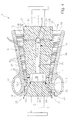
- the rotor 2 is designed in several parts and has in the embodiments of Fig. 1 to 5 each have two rotor parts 2a and 2b, the one another in the axial direction limits.
- the rotor 2 is here designed as a "drum rotor" 2, that is, the rotor 2 is realized according to the drum construction.
- the individual rotor parts 2a, 2b form while the "drums" of the drum rotor 2. They are characterized by their massive Construction with large material thickness in the radial and axial directions.
- the two rotor parts 2a, 2b are welded together.
- a welding zone 15 is formed, which extends in the circumferential direction and thereby closed circulates. In this way, the welding zone 15 receives a annular shape.
- this weld zone 15 To form this weld zone 15, the two rotor parts 2a, 2b at their End faces 13, 14 each with a recess 16 or 17 of any shape Mistake. When assembled, the two complement each other Recesses 16, 17 to a cavity 18. This cavity 18 is thus of the Welding zone 15 circumferentially enclosed.
- the rotor 2 is also equipped with an internal cooling channel system 19, which allows partially relaxed and thus partially cooled steam can be seen at a position on the rotor surface 20 and this as Cooling steam at least one thermally loaded component of the rotor 2, such as z. B. a thrust balance piston 21 supply. Accordingly, it is the cooling steam around the same medium as the working steam.
- the Cooling channel system 19 comprises at least one inflow channel 22 for this purpose Removal of the cooling steam from the working steam at a position on the Rotor surface 20 at a suitable turbine stage 9. In the present Case, two such inflow channels 22 are shown. It is clear that too more than two inflow channels 22 may be provided, in particular can be arranged star-shaped with respect to the axis of rotation 5.
- At least one outflow channel 23 is provided, which contains the cooling steam by at least one cooling zone, here exemplarily the thrust balance piston 21 and / or to a cooling zone of the rotor 2 or a rotor or Turbine component leads.
- the cooling zone here exemplarily the thrust balance piston 21 and / or to a cooling zone of the rotor 2 or a rotor or Turbine component leads.
- two outflow channels 23 shown In the present case are also two outflow channels 23 shown.
- the cooling channel system 19 comprises at least one cooling channel 24, the or together or in each case for at least one inflow channel 22 connect to the at least one outflow channel 23.
- This way will the cooling steam according to the arrows 25 over the at least one Inflow channel 22 of the respective turbine stage 9 taken over the or Cooling channels 24 the at least one outflow channel 23 is supplied to the Cooling steam in turn the respective cooling zone, z. B. the Schubaus Morgans Kochben 21, supplies. Due to the selected positioning of the Inflowing the inflow channels 22 and the outflow of the Outflow channels 23 is within the cooling channel system 19, a pressure drop, the cooling steam automatically in the desired manner within the Cooling channel system 19 transported.
- the cavity 18 is now integrated into the cooling channel system 19. at the embodiment shown in Fig. 1, this is done by the Cooling channels 24 are each connected to this cavity 18.
- the right illustrated cooling channel 24 is the input side to the inflow channels 22nd connected and output side to the cavity 18.
- the left Cooling channel 24 is connected to the input side of the cavity 18 and On the output side to the outflow channels 23.
- Die Cavity 18 forms a kind of distribution node, the cooling steam over one or more channels 22 or 24 is supplied to one or more Channels 23, 24 distributed.
- the two cooling channels 24 are each Centric to the axis of rotation 5 in the respective rotor part 2a, 2b designed.
- the Design of these cooling channels 24 is particularly simple because the rotor parts 2a, 2b before welding in the region of their depressions 16, 17 centrally can be bored to form these cooling channels 24. A additional, alternatively attached depression in the surface of the respective Rotor part 2a, 2b is not required.
- the inflow channels 22, which are here in the extend substantially radially, can be made in the form of holes become. The same applies to the outflow channels 23, which are here extend diagonally - centrically. In terms of flow direction inside the cooling channel system 19 ends the cooling channel 24 shown on the right Cavity 18, while the cooling channel 24 shown on the left begins at the cavity 18.
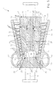
- FIG. 2 differs from that in FIG. 1 shown embodiment in that the rotor part 2a shown on the right no central cooling channel 24, but a plurality of decentralized or with respect to the Rotation axis 5 eccentrically arranged, but parallel to the longitudinal axis extending cooling channels 24 are provided, each with one of Inflow channels 22 communicate.
- the attachment a central cooling channel 24 are avoided, which at certain Rotor designs may be beneficial.
- the number of right in the rotor part 2a trained cooling channels 24 then corresponds to the number of provided there Inflow channels 22.
- the embodiment of Fig. 3 differs from the embodiment 2 in that also in the rotor part 2b shown on the left instead a central cooling channel 24 more decentralized or with respect to the Rotation axis 5 eccentrically arranged cooling channels 24 are provided. Also these cooling channels 24 preferably extend parallel to the longitudinal axis of the Rotor 2 and communicate with one of the outflow channels 23. The number the cooling channels 24 in the rotor part 2b shown on the left then corresponds to the number the outflow channels 23 mounted there, which is not necessarily have to be. Also in the left rotor part 2b can at certain Embodiments of the rotor 2, the attachment of several decentralized or eccentric cooling channels 24 with respect to a central cooling channel 24 advantageous be.
- cooling channels 24 extend parallel to each other eccentrically, such as this is the case, for example, in the embodiments of FIGS. 2 and 3 this expedient symmetrically distributed in the respective rotor part 2a, 2b arranged, that is, the respective cooling channels 24 are concentric about the axis of rotation 5 arranged around.
- the cavity 18 is quasi between the arranged in the axial direction of successive cooling channels 24.
- the Inflow channels 22 and the outflow channels 23 can only via the cooling channels 24th communicate with the cavity 18.
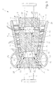
- the pitch of the rotor 2 to the position of Outflow channels 23 adapted, that is, the weld zone 15 is compared to the embodiments of FIGS. 1 to 3 in the direction of the respective cooling zone, ie moved here in the direction of the thrust balance piston 21.
- the outflow 23 directly to the cavity 18 connect. Accordingly, the discharge channels 23 begin at this Embodiment on the cavity 18.
- Cooling channel system 19 As in the embodiment of FIG. 1 designed by a central cooling channel 24 is provided which communicates with the inflow channels 22 communicated.
- FIG. 5 differs from the Embodiment according to FIG. 4 in that in the right rotor part 2a instead the central cooling channel 24 more decentralized or eccentric to Rotary axis 5 arranged cooling channels 24 are provided, each with one of the inflow channels 22 communicate. This can be for certain Embodiments of the rotor 2 may be advantageous.
- the outflow channels 23 are directly on the cavity 18 is connected, while the inflow channels 22 indirectly via the Cooling channels 24 are connected to the cavity 18.
- the pitch of the rotor 2 so is chosen that the inflow channels 22 connected directly to the cavity 18 can be while the outflow channels 23 then indirectly via one or can be connected to the cavity 18 via a plurality of cooling channels 24.
- the Welding zone 15 is then in the direction of the removal point of the cooling steam postponed.
- the at least one cooling channel 24 be formed by the cavity 18, with the result that both the inflow channels 22 and the outflow channels 23 are connected directly to the cavity 18.
- FIGS. 1 to 5 have in common that the at least a sampling points, here the respective turbine stage 9, at a position on the Rotor surface 20 is disposed in the region of a rotor part 2a, while the at least one cooling zone, here the thrust balance piston 21, in the area the other rotor part 2b is arranged.
- the cooling channel system 19 extends thus within the two-piece rotor 2 through both rotor parts 2a and 2b.
- While the rotor 2 in the embodiments of FIGS. 1 to 5 in two parts 6 is an embodiment with a three-part rotor 2, wherein the individual rotor parts from right to left denoted by 2a, 2b and 2c are.
- This rotor 2 is designed as a drum rotor 2. Due to the Three-piece are accordingly two weld zones 15 and thus two Cavities 18 provided. Both cavities 18 are within the meaning of the invention integrated into the cooling channel system 19.
- the division of the rotor 2 is specifically so chosen that the inflow channels 22 directly with the one cavity 18th communicate, while the outflow channels 23 directly with the other cavity 18th communicate.
- the two cavities 18 are then over the at least one Cooling channel 24, here connected to each other via at least two cooling channels 24.
- two or more cooling channels 24 are in the middle rotor part 2b arranged eccentrically.
- a central cooling channel 24 extends between the two cavities 18.
- at least one of the welding zones 15 is positioned so that the associated outer Rotor part 2a or 2c neither an inflow channel 22 nor a discharge channel 23rd contains.
- the welding zone 15 shown on the right can be right next to the cooling steam extraction point be positioned, with the result that the Inflow channels 22 must then be formed in the central rotor part 2b.
- This construction results in that in the right rotor part 2a then no inflow channel 22 is included.
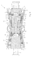
- FIGS. 7 to 9 show twin-flow steam turbines 1.
- the two Floods are designated 26 and 27 respectively.
- the rotor 2 is again in three parts and as a drum rotor. 2 formed, wherein the central rotor part 2b in both floods 26, 27th hineinerstreckt.
- the division of the rotor 2 is done specifically so that the Welding zones 15 with their cavities 18 are each positioned so that the Inflow channels 22 directly to the one, here to the left cavity 18, and the Outflow channels 23 directly to the other, here to the right cavity 18, can be connected.
- the two cavities 18 then communicate via the at least one cooling channel 24 with each other.
- Cooling channel system 19 can thus cooling steam of the flood 27 shown on the left a specific turbine stage 9 are removed and the blading the other flood 26 shown on the right are supplied.
- a suitable Positioning the at least one sampling point and the at least one Return line is created within the cooling channel 19 a sufficient Pressure gradient to drive the cooling steam without additional measures can.
- the two cavities 18 through a centrally arranged cooling channel 24 connected to each other.
- the two cavities 18 by two or more with respect to the rotation axis 5 eccentrically arranged cooling channels 24 connected.
- these cooling channels 24 are around the Rotary axis 5 arranged concentrically distributed around. The number must be the cooling channels 24 neither with the number of inflow channels 22 still with the Number of outflow channels 23 match.
- the inflow channels 22 are in the left shown rotor part 2c, the outflow channels 23 in the rotor part 2a shown on the right and the one or more cooling channels 24 formed in the central rotor part 2b.
- the axial pitch of the rotor 2 specifically so to mount that the inflow channels 22 and / or the outflow 23rd are also arranged in the middle rotor part 2b.
- Fig. 9 shows a preferred Embodiment in which both the inflow channels 22 and the Outflow channels 23 are arranged in the central rotor part 2b, in which also the or the cooling channels 24 are formed.
- the invention is not limited to those described Embodiments limited. It is particularly good for the rotor use of steam turbines in which as a working medium hot steam and Cooling steam is used as the cooling medium, but it goes without saying also suitable for the rotor of an air turbine.
Landscapes
- Engineering & Computer Science (AREA)
- Mechanical Engineering (AREA)
- General Engineering & Computer Science (AREA)
- Turbine Rotor Nozzle Sealing (AREA)
Abstract
Description
Die vorliegende Erfindung betrifft einen Rotor für eine Dampfturbine für Arbeitsdampf, mit den Merkmalen des Oberbegriffs des Anspruchs 1.The present invention relates to a rotor for a steam turbine for Working steam, having the features of the preamble of claim 1.
Ein derartiger Rotor für eine Dampfturbine ist beispielsweise aus der EP 0 991 850 B1 bekannt und erstreckt sich entlang einer Rotationsachse und besteht aus wenigstens zwei in Achsrichtung aneinandergrenzenden Rotorteilen. Dabei sind die beiden Rotorteile an einander zugewandten axialen Stirnseiten mittels einer in Umfangsrichtung geschlossen umlaufenden, ringförmigen Schweißzone miteinander verschweißt. Im Rotor ist ein Kühlkanalsystem ausgebildet, das zumindest einen Zuströmkanal, wenigstens einen Abströmkanal sowie einen Kühlkanal aufweist. Der Kühlkanal führt Kühldampf von wenigstens einem Zuströmkanal zum wenigstens einen Abströmkanal. Der wenigstens eine Zuströmkanal entnimmt den Kühldampf an einer Position an der Rotoroberfläche dem Arbeitsdampf und führt diesen dem Kühlkanal zu. Im Unterschied dazu entnimmt der wenigstens eine Abströmkanal den Kühldampf dem Kühlkanal und führt diesen zu einer bzw. durch eine Kühlzone des Rotors. Durch eine geeignete Positionierung des wenigstens einen Zuströmkanals und des wenigstens einen Abströmkanals kann zwischen und Einlass und Auslass des Kühlkanalsystems eine Druckdifferenz ausgebildet werden, die ausreicht, den Kühldampf ohne zusätzliche Maßnahmen von der wenigstens einen Dampfentnahmestelle zu der wenigstens einen Kühlzone zu fördern.Such a rotor for a steam turbine is known for example from EP 0 991 850 B1 known and extends along a rotation axis and consists of at least two adjoining rotor parts in the axial direction. There are the two rotor parts on mutually facing axial end faces by means of an in Circumferentially closed circumferential, annular weld zone welded together. In the rotor, a cooling channel system is formed at least one inflow channel, at least one outflow channel and a Cooling channel has. The cooling duct carries cooling steam from at least one Inflow channel to at least one outflow channel. The at least one Inflow channel removes the cooling steam at a position on the rotor surface the working steam and this leads to the cooling channel. In contrast to takes the at least one outflow channel the cooling steam the cooling channel and leads this to or through a cooling zone of the rotor. By a suitable Positioning of the at least one inflow channel and the at least one Outflow channel can be between and inlet and outlet of the cooling channel system be formed a pressure difference sufficient, the cooling steam without additional measures from the at least one steam extraction point to the to promote at least one cooling zone.
Beim bekannten Rotor erstreckt sich der Kühlkanal konzentrisch zur Rotationsachse. Die Zuströmkanäle sind im Bereich eines Diffusors einer einflutigen Hochdruckturbine angeordnet, während die Abströmkanäle im Zentrum einer zweiflutigen Mitteldruckturbine positioniert sind. Der Kühlkanal erstreckt sich dabei innerhalb des für die Hochdruckturbine und die Mitteldruckturbine vorgesehenen gemeinsamen Rotors. Dieser Rotor ist axial zwischen Hochdruckturbine und Mitteldruckturbine gelagert. Dementsprechend erstreckt sich die Kühlleitung zentral auch durch dieses Lager. Als Folge davon ist dieses Lager einer erhöhten Temperaturbelastung ausgesetzt, so dass zusätzliche Maßnahmen zum Schutz dieses Lagers erforderlich sind.In the known rotor, the cooling channel extends concentrically to Axis of rotation. The inflow channels are in the region of a diffuser arranged high-pressure turbine, while the outflow channels in the Center of a double-flow medium-pressure turbine are positioned. The cooling channel extends within the for the high-pressure turbine and the Medium-pressure turbine provided common rotor. This rotor is axial stored between high-pressure turbine and medium-pressure turbine. Accordingly The cooling line extends centrally through this camp. As a consequence of this this bearing is exposed to an increased temperature load, so that additional measures are required to protect this warehouse.
Der bekannte Rotor ist nach einer sogenannten "Trommelbauweise" realisiert, d.h., der Rotor ist aus mehreren "Trommeln" zusammengebaut. Bei einer solchen Trommel handelt es sich um einen zylindrischen oder kegelstumpfförmigen Massivkörper, der grundsätzlich Hohlräume, wie Kanäle und Kammern, eines Kühlsystems enthalten kann. Ein Rotor mit Trommelbauweise charakterisiert sich in der Regel durch eine kleine Anzahl von Trommeln, die vorzugsweise unterschiedlich ausgestaltet sind. Dabei ist jede Trommel mehreren Turbinenstufen zugeordnet. Benachbarte Trommeln liegen stirnseitig in der Regel vollflächig aneinander an.The known rotor is realized according to a so-called "drum construction", that is, the rotor is composed of a plurality of "drums". In such a Drum is a cylindrical or frustoconical Massive body, which basically cavities, such as channels and chambers, one Can contain cooling system. A rotor with drum construction characterizes itself usually by a small number of drums, preferably are designed differently. Each drum is several Assigned to turbine stages. Adjacent drums are usually frontally over the entire surface to each other.
Aus der DE 196 20 828 C1 ist ein einteiliger Rotor bekannt, der in einer zweiflutigen Dampfturbine angeordnet ist und ebenfalls ein Kühlkanalsystem enthält. In diesem Rotor ist im Zentrum der Heißdampfzuführung am Mantel ein Hohlraum ausgebildet, der mit Hilfe eines Deckels wieder verschlossen ist, wobei der Deckel gleichzeitig eine Strömungsleitfunktion erfüllt. Von diesem Hohlraum geht an zwei axial gegenüberliegenden Seiten jeweils ein axialer Kühlkanal ab. Der eine Kühlkanal kommuniziert mit einem Zuströmkanal, der den Kühldampf einer Druckstufe der einen Flut entnimmt. Im Unterschied dazu kommuniziert der andere Kühlkanal mit einem Abströmkanal, der den Kühldampf einer Druckstufe der anderen Flut zuführt. Der Aufwand zur Realisierung dieser internen Kühlung ist vergleichsweise groß, da zur Herstellung der Kühlkanäle zunächst der Hohlraum am Umfang des Rotors ausgebildet und anschließend wieder verschlossen werden muss. Ungünstig ist dabei außerdem, dass bei der gewählten Positionierung des Hohlraums genau an derjenigen Stelle des Rotors eine Schwächung in der Struktur erreicht wird, die im Betrieb der Dampfturbine den höchsten thermischen und hohen mechanischen Belastungen ausgesetzt ist. Des Weiteren ist ein zusätzlicher Aufwand erforderlich, um den Hohlraum wieder mittels des entsprechenden Deckels zu verschließen.From DE 196 20 828 C1, a one-piece rotor is known which in a twin-flow steam turbine is arranged and also a cooling duct system contains. In this rotor is in the center of the hot steam supply to the jacket Cavity formed, which is closed by means of a lid, wherein the lid simultaneously fulfills a flow guiding function. From this cavity goes on two axially opposite sides in each case an axial cooling channel. The one cooling channel communicates with an inflow channel, which separates the cooling steam a pressure stage that takes a flood. In contrast, the communicates another cooling channel with a discharge channel, the cooling steam of a pressure stage the other flood supplies. The effort to realize this internal cooling is comparatively large, there for the production of the cooling channels first of Cavity formed on the circumference of the rotor and then again must be closed. Unfavorable is also that in the selected positioning of the cavity exactly at that point of the rotor a weakening in the structure is achieved in the operation of the steam turbine is exposed to the highest thermal and high mechanical loads. Furthermore, additional effort is required to restore the cavity to close by means of the appropriate lid.
Aus der EP 0 761 929 A1 ist ein Rotor für eine Gasturbine bekannt, an dem ein Verdichterteil, ein Mittelteil und ein Turbinenteil ausgebildet sind und der vorwiegend aus einzelnen, miteinander verschweißten Rotationskörpern besteht, deren geometrische Form zur Ausbildung von axial symmetrischen Hohlräumen zwischen den jeweils benachbarten Rotationskörpern führt. Bei diesem Rotor sind ein sich um die Mittelachse des Rotors erstreckender, vom stromabwärtigen Ende des Rotors bis zum stromaufwärts letzten Hohlraum reichender weiterer, zylinderförmiger Hohlraum sowie wenigstens zwei Rohre vorgesehen, die unterschiedliche Durchmesser und Längen aufweisen und sich zumindest teilweise teleskopisch überlappen und die im zylinderförmigen Hohlraum angeordnet sind. Die Rohre sind jeweils an einem Fixpunkt fest verankert, wobei die Fixpunkte der Rohre an axial unterschiedlichen Stellen liegen. Die Rohre sind jeweils mit mindestens zwei Durchgangsöffnungen im Mantel versehen, wobei mindestens eine Öffnung im Turbinenteil und mindestens eine Öffnung im Verdichter- bzw. Mittelteil angeordnet ist. Die Öffnungen der verschiedenen Rohre überlappen sich im Betriebszustand im Turbinenteil und im kalten Zustand im Verdichter- und Mittelteil. Auf diese Weise kann beim Hochfahren der Turbine der Rotor schneller aufgewärmt werden, während im Betriebszustand eine Kühlung bereitgestellt wird. Für die Vorwärmung bzw. für die Kühlung wird dabei an einer geeigneten Verdichterstufe Druckluft entnommen und axial einem der Rohre zugeführt.From EP 0 761 929 A1 a rotor for a gas turbine is known, on which a Compressor, a central part and a turbine part are formed and the consists mainly of individual, welded together rotational bodies, their geometric shape to form axially symmetric cavities leads between the respective adjacent bodies of revolution. In this rotor are one extending around the central axis of the rotor, from the downstream End of the rotor up to the upstream last cavity reaching further, cylindrical cavity and at least two tubes provided, the have different diameters and lengths and at least partly telescopically overlap and in the cylindrical cavity are arranged. The tubes are firmly anchored to a fixed point, wherein the fixed points of the tubes are at axially different locations. The pipes are each provided with at least two through holes in the jacket, wherein at least one opening in the turbine part and at least one opening in the Compressor or middle part is arranged. The openings of the different Tubes overlap in the operating state in the turbine section and in the cold state in the compressor and middle section. In this way, when starting up the turbine The rotor can be warmed up faster while in the operating state Cooling is provided. For preheating or for cooling is doing taken at a suitable compressor stage compressed air and axially one of Pipes supplied.
Dieser bekannte Rotor ist mit der sogenannten "Scheibenbauweise" realisiert, d.h., der Rotor ist aus mehreren "Scheiben" zusammengebaut. Die Scheiben entsprechen scheibenförmigen Körpern, die radial außen einen axial vorstehenden Randbereich aufweisen, der nach Art einer Hülse ausgestaltet sein kann. Die benachbarten Scheiben liegen an den Randbereichen entlang relativ kleiner Ringflächen aneinander an. Bei diesen Scheiben handelt es sich somit um die vorgenannten Rotationskörper. Jede Scheibe ist im Unterschied zu einer Trommel nur wenigen, insbesondere jeweils nur einer einzigen Turbinenstufe zugeordnet. Dementsprechend besteht ein Rotor in Scheibenbauweise aus einer vergleichsweise großen Anzahl an Scheiben, die außerdem vorzugsweise baugleich ausgestaltet sind. Die in einem Rotor mit Scheibenbauweise realisierten Hohlräume dienen vorwiegend zur Reduzierung der Trägheitskräfte, können jedoch zusätzlich für ein Kühlsystem genutzt werden.This known rotor is realized with the so-called "disk construction", that is, the rotor is assembled from a plurality of "slices". The disks correspond disc-shaped bodies, the radially outward axial have protruding edge region, which may be configured in the manner of a sleeve can. The adjacent disks are relatively along the edge regions small annular surfaces to each other. These discs are thus around the aforementioned rotating body. Each disc is different from one Drum only a few, especially in each case only a single turbine stage assigned. Accordingly, a rotor of disk construction consists of a comparatively large number of disks, which also preferably are designed identical. The in a rotor with disk construction realized cavities serve primarily to reduce the inertial forces, However, they can also be used for a cooling system.
Weitere Rotoren für Gasturbinen, die in dieser Scheibenbauweise realisiert sind, können beispielsweise aus der DE 854 445 B, der DE 198 52 604 A1 und der DE 196 17 539 A1 entnommen werden. Further rotors for gas turbines, which are realized in this disk construction, For example, from DE 854 445 B, DE 198 52 604 A1 and DE 196 17 539 A1 be removed.
Die vorliegende Erfindung, wie sie in den Ansprüchen gekennzeichnet ist, beschäftigt sich mit dem Problem, für einen Rotor einer Dampfturbine der eingangs genannten Art eine verbesserte Ausführungsform anzugeben, die insbesondere bei reduziertem Herstellungsaufwand eine hinreichende Kühlung der jeweiligen Kühlzone des Rotors, insbesondere des Rotorinneren, ermöglicht.The present invention as characterized in the claims deals with the problem for a rotor of a steam turbine the mentioned type an improved embodiment, the in particular with reduced production costs sufficient cooling the respective cooling zone of the rotor, in particular the rotor interior, allows.
Erfindungsgemäß wird dieses Problem durch den Gegenstand des unabhängigen Anspruchs gelöst. Vorteilhafte Ausführungsformen sind Gegenstand der abhängigen Ansprüche.According to the invention, this problem is solved by the subject matter of the independent patent Claim solved. Advantageous embodiments are the subject of dependent claims.
Die Erfindung beruht auf dem allgemeinen Gedanken, bei einem Rotor, dessen Rotorteile zum Herstellen der Schweißverbindung stirnseitig jeweils eine Vertiefung aufweisen, die zusammen im verschweißten Zustand eine von der Schweißzone umschlossene Kavität bilden, diese bei der Herstellung des Rotors ohnehin vorhandene Kavität in das Kühlkanalsystem zu integrieren. Durch diese Maßnahme kann die Kavität bzw. können die genannten Vertiefungen vor dem Verschweißen der Rotorteile dazu genutzt werden, den oder die Kühlkanäle und/oder den oder die Zuströmkanäle und/oder den oder die Abströmkanäle in das jeweilige Rotorteil einzubringen. Zusätzliche Ausnehmungen, die einerseits zu einer Materialschwächung führen und andererseits wieder verschlossen werden müssen, sind dadurch entbehrlich. Der Aufwand zur Realisierung des rotorinternen Kühlkanalsystems kann dadurch reduziert werden. Gleichzeitig erhält die Kavität eine sinnvolle Doppelfunktion, wodurch sich insgesamt der Aufwand zur Ausbildung der Schweißverbindung bzw. des Rotors relativiert.The invention is based on the general idea, in a rotor whose Rotor parts for producing the welded joint frontally one each Well, which together in the welded state one of the Sweat zone enclosed cavity, this in the manufacture of the rotor to integrate any existing cavity in the cooling channel system. Through this Measure the cavity or can be said depressions before the Welding of the rotor parts are used to the one or more cooling channels and / or the one or more inflow channels and / or the one or more outflow channels in to introduce the respective rotor part. Additional recesses, on the one hand lead to a material weakening and on the other hand closed again must be dispensable. The effort to realize the internal rotor cooling channel system can be reduced. simultaneously the cavity receives a meaningful double function, which in total the Expenses relative to the formation of the welded joint or the rotor relativized.
Besonders wichtig ist die Kühlung des Rotorzentrums in dem Bereich, in dem der Rotor einen großen Außendurchmesser besitzt und gleichzeitig dort außen mit heißem Arbeitsdampf beaufschlagt wird. Das ist häufig im Bereich der Dichtung am Schubausgleichskolben der Fall, durch die unmittelbar heißer Arbeitsdampf von der Turbineneinströmung strömt und wo gleichzeitig der Durchmesser besonders groß ist.Particularly important is the cooling of the rotor center in the area in which the Rotor has a large outer diameter and at the same time there with outside hot working steam is applied. This is often in the field of sealing at the thrust balance piston of the case, by the directly hot working steam flows from the turbine inlet and where at the same time the diameter is especially big.
Die Kühlwirkung eines kühldampfdurchströmten Bohrungssystems (Kühlkanalsystems) ist besonders groß, wenn anstelle einer großen Bohrung viele kleine Bohrungen als Kühlkanäle verwendet werden, denn dann ist die vom Kühldampf beaufschlagte Kühlkanalwand erheblich größer. Gleichzeitig sollte die Querschnittsfläche eines Kühlkanals klein sein, damit eine große Geschwindigkeit des Kühldampf erreicht und damit der Wärmeübergang, also die Kühlwirkung, verbessert wird. Vorteilhaft verlaufen die vielen Kühlkanäle nicht im Rotorzentrum, da eine Durchbohrung des Rotorzentrums die Festigkeit des Rotors dort erheblich schwächt. Bei Rotorabschnitten mit großem Außendurchmesser ist die mechanische Beanspruchung im Rotorzentrum aufgrund der Rotorfliehkraft von besonderer Bedeutung. Sie stellt häufig eine Grenze des Baubaren dar. Durch die erfindungsgemäße Lösung wird aufgrund der Kühlwirkung die Festigkeit des Rotorzentrums erhöht und die Baubarkeitsgrenzen werden in Richtung größerer Temperaturen des Arbeitsdampfes und größerer Rotordurchmesser verschoben.The cooling effect of a cooling steam flow through bore system (Cooling system) is particularly large if instead of a large bore many small holes are used as cooling channels, because then the of Cooling steam applied cooling duct wall considerably larger. At the same time, the Cross-sectional area of a cooling channel to be small, thus a large Speed of cooling steam reached and thus the heat transfer, so the Cooling effect, is improved. Advantageously, the many cooling channels do not run in the Rotor center, as a piercing of the rotor center, the strength of the Rotor significantly weakens there. For rotor sections with large Outer diameter is the mechanical stress in the rotor center due to the rotor centrifugal force of particular importance. She often hires one Border of the buildable dar. The inventive solution is due to the cooling effect increases the strength of the rotor center and the Baubarkeitsgrenzen be in the direction of higher temperatures of the Working steam and larger rotor diameter shifted.
Besondere Vorteile ergeben sich auch für einen Rotor, der aus wenigstens drei Rotorteilen hergestellt ist und dementsprechend zwei Schweißzonen sowie zwei Kavitäten umfasst. Die beiden Kavitäten können dann durch wenigstens einen Kühlkanal miteinander verbunden sein, während der wenigstens eine Zuströmkanal an der einen Kavität endet und der wenigstens eine Abströmkanal an der anderen Kavität beginnt. Bei dieser Bauweise bilden die Kavitäten quasi Knotenstellen, welche die Kommunikation zwischen dem wenigstens einen Kühlkanal und dem wenigstens einen Zuströmkanal einerseits und dem wenigstens einen Abströmkanal andererseits herstellen. Durch die Anbindung des wenigstens einen Zuströmkanals sowie des wenigstens einen Abströmkanals jeweils an eine der Kavitäten, ist es außerdem möglich, den wenigstens einen Kühlkanal nur im mittleren Rotorteil der drei Rotorteile auszubilden, was den Aufwand zur Realisierung des Kühlkanalsystems reduziert.Particular advantages also result for a rotor consisting of at least three Rotor parts is manufactured and accordingly two welding zones and two Includes cavities. The two cavities can then pass through at least one Cooling channel to be interconnected, while the at least one Inflow channel at the one cavity ends and the at least one outflow channel at the other cavity begins. In this construction, the cavities form quasi Nodes that control the communication between the at least one Cooling channel and the at least one inflow channel on the one hand and the on the other hand make at least one outflow channel. By the connection the at least one inflow channel and the at least one outflow channel each to one of the cavities, it is also possible, the at least one Cooling channel only in the middle rotor part of the three rotor parts form what the Reduced effort to realize the cooling duct system.
Weitere wichtige Merkmale und Vorteile der Erfindung ergeben sich aus den Unteransprüchen, aus den Zeichnungen und aus der zugehörigen Figurenbeschreibung anhand der Zeichnungen.Other important features and advantages of the invention will become apparent from the Subclaims, from the drawings and from the associated Description of the figures with reference to the drawings.
Bevorzugte Ausführungsbeispiele der Erfindung sind in den Zeichnungen dargestellt und werden in der nachfolgenden Beschreibung näher erläutert, wobei sich gleiche Bezugszeichen auf gleiche oder ähnliche oder funktional gleiche Komponenten beziehen. Es zeigen, jeweils schematisch,
- Fig. 1
bis 5 - jeweils einen stark vereinfachten Längsschnitt durch eine einflutige Dampfturbine mit zweiteiligem geschweißten Trommelrotor nach der Erfindung bei unterschiedlichen Ausführungsformen,
- Fig. 6
- einen stark vereinfachten Längsschnitt durch eine einflutige Dampfturbine mit dreiteiligem geschweißten Trommelrotor nach der Erfindung,
- Fig. 7
bis 9 - jeweils einen stark vereinfachten Längsschnitt durch eine zweiflutige Dampfturbine mit dreiteiligem geschweißten Trommelrotor nach der Erfindung bei verschiedenen Ausführungsformen.
- Fig. 1 to 5
- in each case a greatly simplified longitudinal section through a single-flow steam turbine with two-part welded drum rotor according to the invention in different embodiments,
- Fig. 6
- a highly simplified longitudinal section through a single-flow steam turbine with three-piece welded drum rotor according to the invention,
- Fig. 7 to 9
- in each case a greatly simplified longitudinal section through a twin-flow steam turbine with a three-part welded drum rotor according to the invention in various embodiments.
Bei allen Figuren sind nur das Innengehäuse und der Rotor dargestellt, nicht aber das Außengehäuse.In all figures, only the inner housing and the rotor are shown, but not the outer casing.
Nachfolgend wird die Erfindung anhand von Ausführungsbeispielen und der Fig. 1 bis 9 näher erläutert.The invention will be described below with reference to exemplary embodiments and FIGS. 1 to 9 explained in more detail.
Entsprechend Fig. 1 umfasst eine Dampfturbine 1 einen Rotor 2, der an seinen
Axialenden 3 und 4 um eine zentrale Rotationsachse 5 drehend gelagert ist. Der
Rotor 2 ist zentrisch in einem Gehäuse 6 angeordnet, das mehrere Leitschaufeln
7 trägt. Korrespondierend dazu trägt der Rotor 2 mehrere Laufschaufeln 8, wobei
die Laufschaufeln 8 und die Leitschaufeln 7 paarweise die Turbinenstufen 9 der
Dampfturbine 1 bilden. Bekanntermaßen arbeitet eine Dampfturbine 1 mit Dampf
als Arbeitsmedium, auch Arbeitsdampf genannt. Das Gehäuse 6 enthält einen
Zuströmraum 10, dem der gespannte Dampf zugeführt wird und von dem der
Dampf zur ersten Turbinenstufe 9 der Dampfturbine 1 geführt wird. Der
entspannte Dampf wird an einem Austritt 11 des Gehäuses 6 abgeführt. Pfeile 12
symbolisieren dabei die Hauptströmung des Dampfes durch die Dampfturbine 1.According to FIG. 1, a steam turbine 1 comprises a
Der Rotor 2 ist mehrteilig ausgeführt und besitzt bei den Ausführungsformen der
Fig. 1 bis 5 jeweils zwei Rotorteile 2a und 2b, die in Achsrichtung aneinander
grenzen. Der Rotor 2 ist hier als "Trommelrotor" 2 ausgestaltet, d.h., der Rotor 2
ist nach der Trommelbauweise realisiert. Die einzelnen Rotorteile 2a, 2b bilden
dabei die "Trommeln" des Trommelrotors 2. Sie zeichnen sich durch ihre massive
Bauweise mit großer Materialstärker in radialer und axialer Richtung aus. The
Die beiden Rotorteile 2a, 2b sind miteinander verschweißt. Zu diesem Zweck ist
an einander zugewandten axialen Stirnseiten 13 und 14 der Rotorteile 2a, 2b
eine Schweißzone 15 ausgebildet, die sich in Umfangsrichtung erstreckt und
dabei geschlossen umläuft. Auf diese Weise erhält die Schweißzone 15 eine
ringförmige Gestalt.The two
Zur Ausbildung dieser Schweißzone 15 sind die beiden Rotorteile 2a, 2b an ihren
Stirnseiten 13, 14 jeweils mit einer Vertiefung 16 bzw. 17 beliebiger Gestalt
versehen. Im zusammengebauten Zustand ergänzen sich die beiden
Vertiefungen 16, 17 zu einer Kavität 18. Diese Kavität 18 ist somit von der
Schweißzone 15 umfangsmäßig umschlossen.To form this
Der Rotor 2 ist außerdem mit einem internen Kühlkanalsystem 19 ausgestattet,
das es ermöglicht, teilweise entspannten und somit teilweise abgekühlten Dampf
an einer Position an der Rotoroberfläche 20 zu entnehmen und diesen als
Kühldampf zumindest einem thermisch belasteten Bestandteil des Rotors 2, wie
z. B. einem Schubausgleichskolben 21 zuzuführen. Demnach handelt es sich
beim Kühldampf um dasselbe Medium wie beim Arbeitsdampf. Das
Kühlkanalsystem 19 umfasst hierzu zumindest einen Zuströmkanal 22 zur
Entnahme des Kühldampfes aus dem Arbeitsdampf an einer Position an der
Rotoroberfläche 20 an einer dazu geeigneten Turbinenstufe 9. Im vorliegenden
Fall sind zwei derartigen Zuströmkanäle 22 dargestellt. Es ist klar, dass auch
mehr als zwei Zuströmkanäle 22 vorgesehen sein können, die insbesondere
sternförmig bezüglich der Rotationsachse 5 angeordnet sein können. Des
Weiteren ist wenigstens ein Abströmkanal 23 vorgesehen, der den Kühldampf
durch wenigstens eine Kühlzone, hier exemplarisch der Schubausgleichskolben
21 und/oder zu einer Kühlzone des Rotors 2 oder eines Rotor- bzw.
Turbinenbauteils führt. Im vorliegenden Fall sind ebenfalls zwei Abströmkanäle
23 dargestellt. Es können jedoch auch mehr als zwei Abströmkanäle 23
vorgesehen sein, die insbesondere sternförmig bezüglich der Rotationsachse 5
angeordnet sein können.The
Des Weiteren umfasst das Kühlkanalsystem 19 zumindest einen Kühlkanal 24,
der bzw. die zusammen oder jeweils für sich den wenigstens einen Zuströmkanal
22 mit dem wenigstens einen Abströmkanal 23 verbinden. Auf diese Weise wird
der Kühldampf entsprechend den Pfeilen 25 über den wenigstens einen
Zuströmkanal 22 der jeweiligen Turbinenstufe 9 entnommen, über den oder die
Kühlkanäle 24 dem wenigstens einen Abströmkanal 23 zugeführt, der den
Kühldampf seinerseits der jeweiligen Kühlzone, z. B. dem
Schubausgleichskolben 21, zuführt. Durch die gewählte Positionierung der
Einströmenden der Zuströmkanäle 22 und der Ausströmenden der
Abströmkanäle 23 besteht innerhalb des Kühlkanalsystems 19 ein Druckgefälle,
das den Kühldampf selbsttätig in der gewünschten Weise innerhalb des
Kühlkanalsystems 19 transportiert.Furthermore, the cooling
Erfindungsgemäß ist nun die Kavität 18 in das Kühlkanalsystem 19 integriert. Bei
der in Fig. 1 gezeigten Ausführungsform erfolgt dies dadurch, dass die
Kühlkanäle 24 jeweils an diese Kavität 18 angeschlossen sind. Der rechts
dargestellte Kühlkanal 24 ist eingangsseitig an die Zuströmkanäle 22
angeschlossen und ausgangsseitig an die Kavität 18. Der links dargestellte
Kühlkanal 24 ist eingangsseitig an die Kavität 18 angeschlossen und
ausgangsseitig an die Abströmkanäle 23. Auf diese Weise wird die Kavität 18 zu
einem vom Kühldampf durchströmten Bestandteil des Kühlkanalsystems 19. Die
Kavität 18 bildet dabei eine Art Verteilerknoten, der den Kühldampf, der über
einen oder mehrere Kanäle 22 oder 24 zugeführt wird, auf einen oder mehrere
Kanäle 23, 24 verteilt. According to the invention, the
Bei der Ausführungsform gemäß Fig. 1 sind die beiden Kühlkanäle 24 jeweils
zentrisch zur Rotationsachse 5 im jeweiligen Rotorteil 2a, 2b ausgestaltet. Die
Ausbildung dieser Kühlkanäle 24 ist dabei besonders einfach, da die Rotorteile
2a, 2b vor dem Verschweißen im Bereich ihrer Vertiefungen 16, 17 zentral
aufgebohrt werden können, um diese Kühlkanäle 24 auszubilden. Eine
zusätzliche, hilfsweise angebrachte Vertiefung in der Oberfläche des jeweiligen
Rotorteils 2a, 2b ist nicht erforderlich. Die Zuströmkanäle 22, die sich hier im
wesentlichen radial erstrecken, können in Form von Bohrungen hergestellt
werden. Entsprechendes gilt auch für die Abströmkanäle 23, die sich hier
diagonal - zentrisch erstrecken. Im Hinblick auf die Strömungsrichtung innerhalb
des Kühlkanalsystems 19 endet der rechts dargestellte Kühlkanal 24 an der
Kavität 18, während der links dargestellte Kühlkanal 24 an der Kavität 18 beginnt.In the embodiment according to FIG. 1, the two
Die in Fig. 2 gezeigte Ausführungsform unterscheidet sich von der in Fig. 1
gezeigten Ausführungsform dadurch, dass im rechts dargestellten Rotorteil 2a
kein zentraler Kühlkanal 24, sondern mehrere dezentrale bzw. bezüglich der
Rotationsachse 5 exzentrisch angeordnete, jedoch parallel zur Längsachse
verlaufende Kühlkanäle 24 vorgesehen sind, die jeweils mit einem der
Zuströmkanäle 22 kommunizieren. Bei dieser Bauweise kann die Anbringung
eines zentralen Kühlkanals 24 vermieden werden, was bei bestimmten
Rotorbauformen von Vorteil sein kann. Die Anzahl der im rechten Rotorteil 2a
ausgebildeten Kühlkanäle 24 entspricht dann der Anzahl der dort vorgesehenen
Zuströmkanäle 22.The embodiment shown in FIG. 2 differs from that in FIG. 1
shown embodiment in that the
In einer weiteren nicht dargestellten Ausführungsform können auch mehrere
fächerartig angeordnete Zuströmkanäle 22 auf einen Kühlkanal 24 treffen.In a further embodiment, not shown, also several
fan-like arranged
Die Ausführungsform der Fig. 3 unterscheidet sich von der Ausführungsform
gemäß Fig. 2 dadurch, dass außerdem im links dargestellten Rotorteil 2b anstelle
eines zentralen Kühlkanals 24 mehrere dezentrale bzw. bezüglich der
Rotationsachse 5 exzentrisch angeordnete Kühlkanäle 24 vorgesehen sind. Auch
diese Kühlkanäle 24 erstrecken sich vorzugsweise parallel zur Längsachse des
Rotors 2 und kommunizieren jeweils mit einem der Abströmkanäle 23. Die Anzahl
der Kühlkanäle 24 im links dargestellten Rotorteil 2b entspricht dann der Anzahl
der dort angebrachten Abströmkanäle 23, wobei dies nicht notwendigerweise
sein muss. Auch beim linken Rotorteil 2b kann bei bestimmten
Ausführungsformen des Rotors 2 die Anbringung mehrerer dezentraler oder
exzentrischer Kühlkanäle 24 gegenüber einem zentralen Kühlkanal 24 vorteilhaft
sein.The embodiment of Fig. 3 differs from the
Sobald mehrere Kühlkanäle 24 parallel zueinander exzentrisch verlaufen, wie
dies beispielsweise bei den Ausführungsformen der Fig. 2 und 3 der Fall ist, sind
diese zweckmäßig symmetrisch verteilt im jeweiligen Rotorteil 2a, 2b angeordnet,
das heißt, die jeweiligen Kühlkanäle 24 sind konzentrisch um die Rotationsachse
5 herum angeordnet.As soon as a plurality of
Bei den Ausführungsformen der Fig. 1 bis 3 ist die Kavität 18 quasi zwischen den
in Achsrichtung aufeinander folgenden Kühlkanälen 24 angeordnet. Die
Zuströmkanäle 22 und die Abströmkanäle 23 können nur über die Kühlkanäle 24
mit der Kavität 18 kommunizieren. Im Unterschied dazu ist bei der
Ausführungsform gemäß Fig. 4 die Teilung des Rotors 2 an die Position der
Abströmkanäle 23 adaptiert, das heißt, die Schweißzone 15 ist im Vergleich zu
den Ausführungsformen der Fig. 1 bis 3 in Richtung der jeweiligen Kühlzone, also
hier in Richtung des Schubausgleichskolbens 21 verschoben. Bei dieser
Bauweise ist es möglich, die Abströmkanäle 23 direkt mit der Kavität 18 zu
verbinden. Dementsprechend beginnen die Abströmkanäle 23 bei dieser
Ausführungsform an der Kavität 18. Dies bedeutet eine erhebliche Vereinfachung
der Herstellung des Kühlkanalsystems 19, da im linken Rotorteil 2b kein
Kühlkanal 24 ausgebildet werden muss. Im rechten Rotorteil 2a ist das
Kühlkanalsystem 19 wie in der Ausführungsform gemäß Fig. 1 gestaltet, indem
ein zentraler Kühlkanal 24 vorgesehen ist, der mit den Zuströmkanälen 22
kommuniziert.In the embodiments of FIGS. 1 to 3, the
Die in Fig. 5 gezeigte Ausführungsform unterscheidet sich von der
Ausführungsform gemäß Fig. 4 dadurch, dass im rechten Rotorteil 2a anstelle
des zentralen Kühlkanals 24 mehrere dezentrale bzw. exzentrisch zur
Rotationsachse 5 angeordnete Kühlkanäle 24 vorgesehen sind, die jeweils mit
einem der Zuströmkanäle 22 kommunizieren. Dies kann für bestimmte
Ausführungsformen des Rotors 2 von Vorteil sein.The embodiment shown in Fig. 5 differs from the
Embodiment according to FIG. 4 in that in the
Bei den Ausführungsformen der Fig. 4 und 5 sind die Abströmkanäle 23 direkt an
die Kavität 18 angeschlossen, während die Zuströmkanäle 22 indirekt über die
Kühlkanäle 24 an die Kavität 18 angeschlossen sind. Grundsätzlich ist auch eine
andere Ausführungsform möglich, bei welcher die Teilung des Rotors 2 so
gewählt ist, dass die Zuströmkanäle 22 direkt an die Kavität 18 angeschlossen
werden können, während die Abströmkanäle 23 dann indirekt über einen oder
über mehrere Kühlkanäle 24 an die Kavität 18 angeschlossen sein können. Die
Schweißzone 15 ist dann in Richtung der Entnahmestelle des Kühldampfes
verschoben.In the embodiments of FIGS. 4 and 5, the
Bei einer anderen Ausführungsform kann der wenigstens eine Kühlkanal 24
durch die Kavität 18 gebildet sein, mit der Folge, dass sowohl die Zuströmkanäle
22 als auch die Abströmkanäle 23 direkt an die Kavität 18 angeschlossen sind.In another embodiment, the at least one
Bei den Ausführungsformen der Fig. 1 bis 5 ist gemeinsam, dass die wenigstens
eine Entnahmestellen, hier die jeweilige Turbinenstufe 9, an einer Position an der
Rotoroberfläche 20 im Bereich des einen Rotorteils 2a angeordnet ist, während
die wenigstens eine Kühlzone, hier der Schubausgleichskolben 21, im Bereich
des anderen Rotorteils 2b angeordnet ist. Dies hat zur Folge, dass bei diesen
Ausführungsformen der wenigstens eine Zuströmkanal 22 zwangsläufig in dem
einen Rotorteil 2a angeordnet ist, während der wenigstens eine Abströmkanal 23
in dem anderen Rotorteil 2b angeordnet ist. Das Kühlkanalsystem 19 erstreckt
sich somit innerhalb des zweiteiligen Rotors 2 durch beide Rotorteile 2a und 2b.In the embodiments of FIGS. 1 to 5 have in common that the at least
a sampling points, here the
Während der Rotor 2 bei den Ausführungsformen der Fig. 1 bis 5 zweiteilig
ausgestaltet ist, zeigt Fig. 6 eine Ausführungsform mit einem dreiteiligen Rotor 2,
wobei die einzelnen Rotorteile von rechts nach links mit 2a, 2b und 2c bezeichnet
sind. Auch dieser Rotor 2 ist als Trommelrotor 2 ausgestaltet. Aufgrund der
Dreiteiligkeit sind dementsprechend zwei Schweißzonen 15 und somit auch zwei
Kavitäten 18 vorgesehen. Dabei sind im Sinne der Erfindung beide Kavitäten 18
in das Kühlkanalsystem 19 integriert. Die Teilung des Rotors 2 ist dabei gezielt so
gewählt, dass die Zuströmkanäle 22 direkt mit der einen Kavität 18
kommunizieren, während die Abströmkanäle 23 direkt mit der anderen Kavität 18
kommunizieren. Die beiden Kavitäten 18 sind dann über den wenigstens einen
Kühlkanal 24, hier über wenigstens zwei Kühlkanäle 24 miteinander verbunden.
Diese gezielte Teilung des Rotors 2 vereinfacht die Integration des
Kühlkanalsystems 19 in den Rotor 2. Denn sowohl für die Ausbildung der
Zuströmkanäle 22 als auch für die Ausbildung der Abströmkanäle 23 können
einfache Bohrungen vorgesehen werden, die von der jeweiligen Entnahmestelle
beziehungsweise von der jeweiligen Kühlzone zur jeweiligen Kavität 18 führen.
Des Weiteren können auch der oder die Kühlkanäle 24 durch einfache
Bohrungen hergestellt werden. Bei der in Fig. 6 gezeigten Ausführungsform sind
demnach im rechts dargestellten Rotorteil 2a ausschließlich die Zuströmkanäle
22 und im links dargestellten Rotorteil 2c ausschließlich die Abströmkanäle 23
ausgebildet, während das mittlere Rotorteil 2b ausschließlich den oder die
Kühlkanäle 24 enthält. While the
Beim Rotor 2 sind im mittleren Rotorteil 2b zwei oder mehr Kühlkanäle 24
exzentrisch angeordnet. Ebenso ist eine Ausführungsform möglich, bei der sich
ein zentraler Kühlkanal 24 zwischen den beiden Kavitäten 18 erstreckt. Des
weiteren ist grundsätzlich auch eine Ausführungsform möglich, bei der zumindest
eine der Schweißzonen 15 so positioniert ist, dass das zugehörige äußere
Rotorteil 2a oder 2c weder einen Zuströmkanal 22 noch einen Abströmkanal 23
enthält. Beispielsweise kann die rechts gezeigte Schweißzone 15 rechts neben
der Kühldampfentnahmestelle positioniert sein, mit der Folge, dass die
Zuströmkanäle 22 dann im mittleren Rotorteil 2b ausgebildet werden müssen.
Diese Bauweise führt dazu, dass im rechten Rotorteil 2a dann kein Zuströmkanal
22 enthalten ist. Dies hat den Vorteil, dass das rechte Rotorteil 2a überhaupt
nicht bearbeitet werden muss, um das rotorinterne Kühlkanalsystem 19
auszubilden. Entsprechendes gilbt dann auch für die links gezeigte Schweißzone
15 im Hinblick auf die Abströmkanäle 23.In the
Während bei den Ausführungsformen der Fig. 1 bis 6 die Dampfturbine 1 einflutig
ausgestaltet ist, zeigen die Fig. 7 bis 9 zweiflutige Dampfturbinen 1. Die beiden
Fluten sind dabei mit 26 bzw. 27 bezeichnet. Bei dieser zweiflutigen
Dampfturbine 1 ist der Rotor 2 wieder dreiteilig und als Trommelrotor 2
ausgebildet, wobei sich das mittlere Rotorteil 2b in beide Fluten 26, 27
hineinerstreckt. Die Teilung des Rotors 2 erfolgt gezielt so, dass die
Schweißzonen 15 mit ihren Kavitäten 18 jeweils so positioniert sind, dass die
Zuströmkanäle 22 direkt an die eine, hier an die linke Kavität 18, und die
Abströmkanäle 23 direkt an die andere, hier an die rechte Kavität 18,
angeschlossen werden können. Die beiden Kavitäten 18 kommunizieren dann
über den wenigstens einen Kühlkanal 24 miteinander. Mit Hilfe des
Kühlkanalsystems 19 kann somit Kühldampf der links dargestellten Flut 27 an
einer bestimmten Turbinenstufe 9 entnommen werden und der Beschaufelung
der rechts dargestellten anderen Flut 26 zugeführt werden. Durch eine geeignete
Positionierung der wenigstens einen Entnahmestelle sowie der wenigstens einen
Rückleitungsstelle entsteht innerhalb des Kühlkanalsystems 19 ein hinreichendes
Druckgefälle, um den Kühldampf ohne zusätzliche Maßnahmen antreiben zu
können.While in the embodiments of Figs. 1 to 6, the steam turbine 1 einflutig
is configured, FIGS. 7 to 9 show twin-flow steam turbines 1. The two
Floods are designated 26 and 27 respectively. In this double-flowed
Steam turbine 1, the
Auch bei dieser Ausführungsform wird deutlich, dass durch die Integration der
Kavitäten 18 in das Kühlkanalsystem 19 der Aufwand zur Realisierung des
Kühlkanalsystems 19 relativ gering ist, da die Vertiefungen 16, 17 in den
Stirnseiten 13, 14 der Rotorteile 2a, 2b, 2c das Einbringen der Zuströmkanäle 22
und der Abströmkanäle 23 sowie der Kühlkanäle 24 erheblich vereinfachen.Also in this embodiment, it is clear that by integrating the
Bei der Ausführungsform gemäß Fig. 7 sind die beiden Kavitäten 18 durch einen
zentral angeordneten Kühlkanal 24 miteinander verbunden. Im Unterschied dazu
sind bei der Ausführungsform gemäß Fig. 8 die beiden Kavitäten 18 durch zwei
oder mehr bezüglich der Rotationsachse 5 exzentrisch angeordnete Kühlkanäle
24 miteinander verbunden. Zweckmäßig sind diese Kühlkanäle 24 um die
Rotationsachse 5 herum konzentrisch verteilt angeordnet. Dabei muss die Anzahl
der Kühlkanäle 24 weder mit der Anzahl der Zuströmkanäle 22 noch mit der
Anzahl der Abströmkanäle 23 übereinstimmen.In the embodiment of FIG. 7, the two
Bei den Ausführungsformen der Fig. 7 und 8 sind die Zuströmkanäle 22 im links
dargestellten Rotorteil 2c, die Abströmkanäle 23 im rechts gezeigten Rotorteil 2a
und der oder die Kühlkanäle 24 im mittleren Rotorteil 2b ausgebildet.
Grundsätzlich ist es möglich, die axiale Teilung des Rotors 2 gezielt so
anzubringen, dass die Zuströmkanäle 22 und/oder die Abströmkanäle 23
ebenfalls im mittleren Rotorteil 2b angeordnet sind. Fig. 9 zeigt eine bevorzugte
Ausführungsform, bei der sowohl die Zuströmkanäle 22 als auch die
Abströmkanäle 23 im mittleren Rotorteil 2b angeordnet sind, in dem auch der
oder die Kühlkanäle 24 ausgebildet sind. Bei dieser Bauweise muss somit nur
das mittlere Rotorteil 2b bearbeitet werden, um das Kühlkanalsystem 19 im
gesamten Rotor 2 auszubilden. Der Aufwand zur Realisierung des
Kühlkanalsystems 19 wird dadurch reduziert.In the embodiments of FIGS. 7 and 8, the
Selbstverständlich ist die Erfindung nicht auf die beschriebenen Ausführungsbeispiele begrenzt. Sie lässt sich zwar besonders gut für den Rotor von Dampfturbinen einsetzen, bei denen als Arbeitsmedium heißer Dampf und als Kühlmedium Kühldampf verwendet wird, aber sie ist selbstverständlich ebenfalls einsetzbar für den Rotor einer Luftturbine. Of course, the invention is not limited to those described Embodiments limited. It is particularly good for the rotor use of steam turbines in which as a working medium hot steam and Cooling steam is used as the cooling medium, but it goes without saying also suitable for the rotor of an air turbine.
- 11
- Dampfturbinesteam turbine
- 22
- Rotorrotor
- 2a2a
- Rotorteilrotor part
- 2b2 B
- Rotorteilrotor part
- 2c2c
- Rotorteilrotor part
- 33
- Axialende von 2Axial end of 2
- 44
- Axialende von 2Axial end of 2
- 55
- Rotationsachseaxis of rotation
- 66
- Gehäusecasing
- 77
- Leitschaufelvane
- 88th
- Laufschaufelblade
- 99
- Turbinenstufeturbine stage
- 1010
- Zuströmrauminflow
- 1111
- Austrittexit
- 1212
- Hauptströmungmainstream
- 1313
- Stirnseitefront
- 1414
- Stirnseitefront
- 1515
- Schweißzonewelding zone
- 1616
- Vertiefungdeepening
- 1717
- Vertiefungdeepening
- 1818
- Kavitätcavity
- 1919
- KühlkanalsystemCooling duct system
- 2020
- Rotoroberflächerotor surface
- 2121
- SchubausgleichskolbenThrust balance piston
- 2222
- Zuströmkanalinflow
- 2323
- Abströmkanal outflow channel
- 2424
- Kühlkanalcooling channel
- 2525
- KühldampfströmungCooling steam flow
- 2626
- Flutflood
- 2727
- Flutflood
Claims (13)
dadurch gekennzeichnet,
characterized,
dadurch gekennzeichnet,
characterized,
dadurch gekennzeichnet,
characterized,
dadurch gekennzeichnet,
characterized,
dadurch gekennzeichnet, dass sich der wenigstens eine Zuströmkanal (22) in dem einen Rotorteil (2a) erstreckt, während sich der wenigstens eine Abströmkanal (23) im anderen Rotorteil (2b) erstreckt.Rotor according to one of claims 1 to 5,
characterized in that the at least one inflow channel (22) extends in one rotor part (2a), while the at least one outflow channel (23) extends in the other rotor part (2b).
dadurch gekennzeichnet,
characterized,
dadurch gekennzeichnet,
characterized,
dadurch gekennzeichnet,
characterized,
dadurch gekennzeichnet,
characterized,
dadurch gekennzeichnet,
characterized,
dadurch gekennzeichnet,
characterized,
dadurch gekennzeichnet, dass der Rotor (2) nach der Trommelbauweise als Trommelrotor (2) aus mehreren, durch die Rotorteile (2a, 2b, 2c) gebildeten Trommeln aufgebaut ist.Rotor according to one of claims 1 to 12,
characterized in that the rotor (2) is constructed according to the drum construction as a drum rotor (2) of a plurality of drums formed by the rotor parts (2a, 2b, 2c).
Applications Claiming Priority (2)
| Application Number | Priority Date | Filing Date | Title |
|---|---|---|---|
| DE10355738 | 2003-11-28 | ||
| DE10355738A DE10355738A1 (en) | 2003-11-28 | 2003-11-28 | Rotor for a turbine |
Publications (3)
| Publication Number | Publication Date |
|---|---|
| EP1536102A2 true EP1536102A2 (en) | 2005-06-01 |
| EP1536102A3 EP1536102A3 (en) | 2012-08-22 |
| EP1536102B1 EP1536102B1 (en) | 2019-03-20 |
Family
ID=34442341
Family Applications (1)
| Application Number | Title | Priority Date | Filing Date |
|---|---|---|---|
| EP04105832.2A Expired - Lifetime EP1536102B1 (en) | 2003-11-28 | 2004-11-17 | Rotor for a steam turbine |
Country Status (3)
| Country | Link |
|---|---|
| US (1) | US7267525B2 (en) |
| EP (1) | EP1536102B1 (en) |
| DE (1) | DE10355738A1 (en) |
Cited By (9)
| Publication number | Priority date | Publication date | Assignee | Title |
|---|---|---|---|---|
| EP1895094A1 (en) * | 2006-08-25 | 2008-03-05 | Siemens Aktiengesellschaft | Swirl cooled rotor welding seam |
| EP1911933A1 (en) * | 2006-10-09 | 2008-04-16 | Siemens Aktiengesellschaft | Rotor for a turbomachine |
| EP1936115A2 (en) | 2006-12-15 | 2008-06-25 | Kabushiki Kaisha Toshiba | Turbine rotor and steam turbine |
| EP1849959A3 (en) * | 2006-04-26 | 2009-12-23 | Kabushiki Kaisha Toshiba | Steam turbine and turbine rotor |
| EP2211017A1 (en) * | 2009-01-27 | 2010-07-28 | Siemens Aktiengesellschaft | Rotor with cavity for a turbo engine |
| EP2565419A1 (en) * | 2011-08-30 | 2013-03-06 | Siemens Aktiengesellschaft | Flow machine cooling |
| US8454297B2 (en) | 2007-11-02 | 2013-06-04 | Alstom Technology Ltd | Method for determining the remaining service life of a rotor of a thermally loaded turboengine |
| EP2264281A3 (en) * | 2009-05-27 | 2014-02-19 | Pratt & Whitney Canada Corp. | Anti-vortex device for a gas turbine engine compressor |
| EP2998506A1 (en) * | 2014-09-19 | 2016-03-23 | Siemens Aktiengesellschaft | System for reducing the start-up time of a steam turbine |
Families Citing this family (20)
| Publication number | Priority date | Publication date | Assignee | Title |
|---|---|---|---|---|
| JP4777489B2 (en) * | 1997-03-31 | 2011-09-21 | ザ チルドレンズ メディカル センター コーポレーション | Nitrosylation to inactivate apoptotic enzymes |
| EP1780376A1 (en) * | 2005-10-31 | 2007-05-02 | Siemens Aktiengesellschaft | Steam turbine |
| EP1793091A1 (en) * | 2005-12-01 | 2007-06-06 | Siemens Aktiengesellschaft | Steam turbine with bearing struts |
| GB0616832D0 (en) * | 2006-08-25 | 2006-10-04 | Alstom Technology Ltd | Turbomachine |
| JP4908137B2 (en) * | 2006-10-04 | 2012-04-04 | 株式会社東芝 | Turbine rotor and steam turbine |
| US8105032B2 (en) * | 2008-02-04 | 2012-01-31 | General Electric Company | Systems and methods for internally cooling a wheel of a steam turbine |
| US8484975B2 (en) * | 2008-02-05 | 2013-07-16 | General Electric Company | Apparatus and method for start-up of a power plant |
| US8251643B2 (en) * | 2009-09-23 | 2012-08-28 | General Electric Company | Steam turbine having rotor with cavities |
| EP2573317A1 (en) * | 2011-09-21 | 2013-03-27 | Siemens Aktiengesellschaft | Rotor for a steam turbine |
| US8926273B2 (en) | 2012-01-31 | 2015-01-06 | General Electric Company | Steam turbine with single shell casing, drum rotor, and individual nozzle rings |
| CA2903784C (en) | 2013-03-04 | 2021-03-16 | Echogen Power Systems, L.L.C. | Heat engine systems with high net power supercritical carbon dioxide circuits |
| WO2014197343A1 (en) * | 2013-06-06 | 2014-12-11 | Dresser-Rand Company | Compressor having hollow shaft |
| WO2016073252A1 (en) | 2014-11-03 | 2016-05-12 | Echogen Power Systems, L.L.C. | Active thrust management of a turbopump within a supercritical working fluid circuit in a heat engine system |
| US10883388B2 (en) | 2018-06-27 | 2021-01-05 | Echogen Power Systems Llc | Systems and methods for generating electricity via a pumped thermal energy storage system |
| JP7242597B2 (en) * | 2020-03-12 | 2023-03-20 | 東芝エネルギーシステムズ株式会社 | turbine rotor |
| US11435120B2 (en) | 2020-05-05 | 2022-09-06 | Echogen Power Systems (Delaware), Inc. | Split expansion heat pump cycle |
| AU2021397292A1 (en) | 2020-12-09 | 2023-07-06 | Supercritical Storage Company, Inc. | Three reservoir electric thermal energy storage system |
| US12516855B2 (en) | 2022-10-27 | 2026-01-06 | Supercritical Storage Company, Inc. | High-temperature, dual rail heat pump cycle for high performance at high-temperature lift and range |
| US12331664B2 (en) | 2023-02-07 | 2025-06-17 | Supercritical Storage Company, Inc. | Waste heat integration into pumped thermal energy storage |
| CN116923684B (en) * | 2023-06-28 | 2025-10-28 | 上海机电工程研究所 | Flow channel type aircraft nose cone partition cooling system and aircraft nose cone |
Family Cites Families (13)
| Publication number | Priority date | Publication date | Assignee | Title |
|---|---|---|---|---|
| DE854445C (en) * | 1948-11-27 | 1952-11-04 | Brown Ag | Liquid-cooled gas turbine runner |
| CH353218A (en) * | 1957-09-18 | 1961-03-31 | Escher Wyss Ag | An axial turbine rotor composed of disks |
| DE4411616C2 (en) * | 1994-04-02 | 2003-04-17 | Alstom | Method for operating a turbomachine |
| DE19531290A1 (en) | 1995-08-25 | 1997-02-27 | Abb Management Ag | Rotor for thermal turbomachinery |
| DE19617539B4 (en) * | 1996-05-02 | 2006-02-09 | Alstom | Rotor for a thermal turbomachine |
| DE19620828C1 (en) | 1996-05-23 | 1997-09-04 | Siemens Ag | Steam turbine shaft incorporating cooling circuit |
| WO1997049901A1 (en) * | 1996-06-21 | 1997-12-31 | Siemens Aktiengesellschaft | Turbine shaft and process for cooling it |
| DE19648185A1 (en) * | 1996-11-21 | 1998-05-28 | Asea Brown Boveri | Welded rotor of a turbomachine |
| ES2172905T3 (en) | 1997-06-27 | 2002-10-01 | Siemens Ag | TREE OF A STEAM TURBINE WITH INTERNAL REFRIGERATION, AS WELL AS PROCEDURE FOR THE REFRIGERATION OF A TURBINE TREE. |
| DE19757945B4 (en) * | 1997-12-27 | 2006-11-30 | Alstom | Rotor for thermal turbomachinery |
| DE19852604A1 (en) * | 1998-11-14 | 2000-05-18 | Abb Research Ltd | Rotor for gas turbine, with first cooling air diverting device having several radial borings running inwards through first rotor disk |
| EP1013879A1 (en) * | 1998-12-24 | 2000-06-28 | Asea Brown Boveri AG | Liquid cooled turbomachine shaft |
| JP2003206701A (en) * | 2002-01-11 | 2003-07-25 | Mitsubishi Heavy Ind Ltd | Turbine rotor for gas turbine, and gas turbine |
-
2003
- 2003-11-28 DE DE10355738A patent/DE10355738A1/en not_active Ceased
-
2004
- 2004-11-17 EP EP04105832.2A patent/EP1536102B1/en not_active Expired - Lifetime
- 2004-11-29 US US10/998,383 patent/US7267525B2/en not_active Expired - Lifetime
Cited By (14)
| Publication number | Priority date | Publication date | Assignee | Title |
|---|---|---|---|---|
| EP1849959A3 (en) * | 2006-04-26 | 2009-12-23 | Kabushiki Kaisha Toshiba | Steam turbine and turbine rotor |
| US7850423B2 (en) | 2006-04-26 | 2010-12-14 | Kabushiki Kaisha Toshiba | Steam turbine and turbine rotor |
| EP1895094A1 (en) * | 2006-08-25 | 2008-03-05 | Siemens Aktiengesellschaft | Swirl cooled rotor welding seam |
| EP1911933A1 (en) * | 2006-10-09 | 2008-04-16 | Siemens Aktiengesellschaft | Rotor for a turbomachine |
| WO2008043663A1 (en) * | 2006-10-09 | 2008-04-17 | Siemens Aktiengesellschaft | Rotor for a turbo-machine |
| EP1936115A2 (en) | 2006-12-15 | 2008-06-25 | Kabushiki Kaisha Toshiba | Turbine rotor and steam turbine |
| EP1936115A3 (en) * | 2006-12-15 | 2009-12-02 | Kabushiki Kaisha Toshiba | Turbine rotor and steam turbine |
| US8277173B2 (en) | 2006-12-15 | 2012-10-02 | Kabushiki Kaisha Toshiba | Turbine rotor and steam turbine |
| US8454297B2 (en) | 2007-11-02 | 2013-06-04 | Alstom Technology Ltd | Method for determining the remaining service life of a rotor of a thermally loaded turboengine |
| EP2211017A1 (en) * | 2009-01-27 | 2010-07-28 | Siemens Aktiengesellschaft | Rotor with cavity for a turbo engine |
| EP2264281A3 (en) * | 2009-05-27 | 2014-02-19 | Pratt & Whitney Canada Corp. | Anti-vortex device for a gas turbine engine compressor |
| WO2013029911A1 (en) * | 2011-08-30 | 2013-03-07 | Siemens Aktiengesellschaft | Cooling for a fluid flow machine |
| EP2565419A1 (en) * | 2011-08-30 | 2013-03-06 | Siemens Aktiengesellschaft | Flow machine cooling |
| EP2998506A1 (en) * | 2014-09-19 | 2016-03-23 | Siemens Aktiengesellschaft | System for reducing the start-up time of a steam turbine |
Also Published As
| Publication number | Publication date |
|---|---|
| DE10355738A1 (en) | 2005-06-16 |
| EP1536102A3 (en) | 2012-08-22 |
| EP1536102B1 (en) | 2019-03-20 |
| US7267525B2 (en) | 2007-09-11 |
| US20050118025A1 (en) | 2005-06-02 |
Similar Documents
| Publication | Publication Date | Title |
|---|---|---|
| EP1536102B1 (en) | Rotor for a steam turbine | |
| EP1945911B1 (en) | Steam turbine | |
| DE859089C (en) | Bladed gyroscope through which a work equipment flows | |
| DE2408839C2 (en) | Twin-shaft gas turbine engine | |
| EP2140114B1 (en) | Axial bearing particularly for a turbocharger | |
| DE69018338T2 (en) | Gas turbine. | |
| EP2796668B1 (en) | Casing section of a turbo engine compressor or turbo engine turbine stage | |
| EP1201879B1 (en) | Cooled component, casting core and method for the manufacture of the same | |
| DE2553193A1 (en) | BORE BLADE DEVICE FOR TURBINE BLADES WITH BORE INLET COOLING | |
| EP1389690A1 (en) | Screw interiorly cooled | |
| EP2543865A2 (en) | Turbofan engine with heat exchanger on the core engine housing | |
| EP1180578A1 (en) | Statoric blades for a turbomachine | |
| CH694257A5 (en) | Steam turbine. | |
| EP2173972B1 (en) | Rotor for an axial flow turbomachine | |
| EP2818724A1 (en) | Fluid flow engine, casing treatment and method | |
| DE102014018096A1 (en) | Turbomachine for an energy converter, in particular a fuel cell | |
| DE1601563B2 (en) | Air-cooled blade | |
| WO2008043663A1 (en) | Rotor for a turbo-machine | |
| DE10355230A1 (en) | Rotor for a turbomachine | |
| EP2886807B1 (en) | Cooled flanged connection for a gas turbine engine | |
| DE60024519T2 (en) | Clamping ring for fixing cooling tubes in a gas turbine rotor | |
| EP3321589B1 (en) | Fuel nozzle of a gas turbine with swirl creator | |
| DE68909199T2 (en) | Radial fluid machine. | |
| EP1705339B1 (en) | Rotor shaft, in particular for a gas turbine | |
| DE19757945B4 (en) | Rotor for thermal turbomachinery |
Legal Events
| Date | Code | Title | Description |
|---|---|---|---|
| PUAI | Public reference made under article 153(3) epc to a published international application that has entered the european phase |
Free format text: ORIGINAL CODE: 0009012 |
|
| AK | Designated contracting states |
Kind code of ref document: A2 Designated state(s): AT BE BG CH CY CZ DE DK EE ES FI FR GB GR HU IE IS IT LI LU MC NL PL PT RO SE SI SK TR |
|
| AX | Request for extension of the european patent |
Extension state: AL HR LT LV MK YU |
|
| PUAL | Search report despatched |
Free format text: ORIGINAL CODE: 0009013 |
|
| AK | Designated contracting states |
Kind code of ref document: A3 Designated state(s): AT BE BG CH CY CZ DE DK EE ES FI FR GB GR HU IE IS IT LI LU MC NL PL PT RO SE SI SK TR |
|
| AX | Request for extension of the european patent |
Extension state: AL HR LT LV MK YU |
|
| RIC1 | Information provided on ipc code assigned before grant |
Ipc: F02C 7/16 20060101ALI20120716BHEP Ipc: F01D 5/08 20060101AFI20120716BHEP |
|
| 17P | Request for examination filed |
Effective date: 20130219 |
|
| AKX | Designation fees paid |
Designated state(s): AT BE BG CH CY CZ DE DK EE ES FI FR GB GR HU IE IS IT LI LU MC NL PL PT RO SE SI SK TR |
|
| RAP1 | Party data changed (applicant data changed or rights of an application transferred) |
Owner name: GENERAL ELECTRIC TECHNOLOGY GMBH |
|
| STAA | Information on the status of an ep patent application or granted ep patent |
Free format text: STATUS: EXAMINATION IS IN PROGRESS |
|
| 17Q | First examination report despatched |
Effective date: 20161205 |
|
| GRAP | Despatch of communication of intention to grant a patent |
Free format text: ORIGINAL CODE: EPIDOSNIGR1 |
|
| STAA | Information on the status of an ep patent application or granted ep patent |
Free format text: STATUS: GRANT OF PATENT IS INTENDED |
|
| INTG | Intention to grant announced |
Effective date: 20181002 |
|
| RIN1 | Information on inventor provided before grant (corrected) |
Inventor name: REIGL, MARTIN Inventor name: HIEGEMANN, MICHAEL, DR. |
|
| GRAS | Grant fee paid |
Free format text: ORIGINAL CODE: EPIDOSNIGR3 |
|
| RIC1 | Information provided on ipc code assigned before grant |
Ipc: F01D 5/08 20060101AFI20120716BHEP Ipc: F02C 7/16 20060101ALI20120716BHEP |
|
| GRAA | (expected) grant |
Free format text: ORIGINAL CODE: 0009210 |
|
| STAA | Information on the status of an ep patent application or granted ep patent |
Free format text: STATUS: THE PATENT HAS BEEN GRANTED |
|
| AK | Designated contracting states |
Kind code of ref document: B1 Designated state(s): AT BE BG CH CY CZ DE DK EE ES FI FR GB GR HU IE IS IT LI LU MC NL PL PT RO SE SI SK TR |
|
| REG | Reference to a national code |
Ref country code: GB Ref legal event code: FG4D Free format text: NOT ENGLISH |
|
| REG | Reference to a national code |
Ref country code: CH Ref legal event code: EP |
|
| REG | Reference to a national code |
Ref country code: DE Ref legal event code: R096 Ref document number: 502004015778 Country of ref document: DE |
|
| REG | Reference to a national code |
Ref country code: AT Ref legal event code: REF Ref document number: 1110726 Country of ref document: AT Kind code of ref document: T Effective date: 20190415 |
|
| REG | Reference to a national code |
Ref country code: IE Ref legal event code: FG4D Free format text: LANGUAGE OF EP DOCUMENT: GERMAN |
|
| REG | Reference to a national code |
Ref country code: NL Ref legal event code: MP Effective date: 20190320 |
|
| PG25 | Lapsed in a contracting state [announced via postgrant information from national office to epo] |
Ref country code: SE Free format text: LAPSE BECAUSE OF FAILURE TO SUBMIT A TRANSLATION OF THE DESCRIPTION OR TO PAY THE FEE WITHIN THE PRESCRIBED TIME-LIMIT Effective date: 20190320 Ref country code: FI Free format text: LAPSE BECAUSE OF FAILURE TO SUBMIT A TRANSLATION OF THE DESCRIPTION OR TO PAY THE FEE WITHIN THE PRESCRIBED TIME-LIMIT Effective date: 20190320 |
|
| PG25 | Lapsed in a contracting state [announced via postgrant information from national office to epo] |
Ref country code: BG Free format text: LAPSE BECAUSE OF FAILURE TO SUBMIT A TRANSLATION OF THE DESCRIPTION OR TO PAY THE FEE WITHIN THE PRESCRIBED TIME-LIMIT Effective date: 20190620 Ref country code: NL Free format text: LAPSE BECAUSE OF FAILURE TO SUBMIT A TRANSLATION OF THE DESCRIPTION OR TO PAY THE FEE WITHIN THE PRESCRIBED TIME-LIMIT Effective date: 20190320 Ref country code: GR Free format text: LAPSE BECAUSE OF FAILURE TO SUBMIT A TRANSLATION OF THE DESCRIPTION OR TO PAY THE FEE WITHIN THE PRESCRIBED TIME-LIMIT Effective date: 20190621 |
|
| PG25 | Lapsed in a contracting state [announced via postgrant information from national office to epo] |
Ref country code: CZ Free format text: LAPSE BECAUSE OF FAILURE TO SUBMIT A TRANSLATION OF THE DESCRIPTION OR TO PAY THE FEE WITHIN THE PRESCRIBED TIME-LIMIT Effective date: 20190320 Ref country code: IT Free format text: LAPSE BECAUSE OF FAILURE TO SUBMIT A TRANSLATION OF THE DESCRIPTION OR TO PAY THE FEE WITHIN THE PRESCRIBED TIME-LIMIT Effective date: 20190320 Ref country code: SK Free format text: LAPSE BECAUSE OF FAILURE TO SUBMIT A TRANSLATION OF THE DESCRIPTION OR TO PAY THE FEE WITHIN THE PRESCRIBED TIME-LIMIT Effective date: 20190320 Ref country code: PT Free format text: LAPSE BECAUSE OF FAILURE TO SUBMIT A TRANSLATION OF THE DESCRIPTION OR TO PAY THE FEE WITHIN THE PRESCRIBED TIME-LIMIT Effective date: 20190720 Ref country code: EE Free format text: LAPSE BECAUSE OF FAILURE TO SUBMIT A TRANSLATION OF THE DESCRIPTION OR TO PAY THE FEE WITHIN THE PRESCRIBED TIME-LIMIT Effective date: 20190320 Ref country code: ES Free format text: LAPSE BECAUSE OF FAILURE TO SUBMIT A TRANSLATION OF THE DESCRIPTION OR TO PAY THE FEE WITHIN THE PRESCRIBED TIME-LIMIT Effective date: 20190320 Ref country code: RO Free format text: LAPSE BECAUSE OF FAILURE TO SUBMIT A TRANSLATION OF THE DESCRIPTION OR TO PAY THE FEE WITHIN THE PRESCRIBED TIME-LIMIT Effective date: 20190320 |
|
| PG25 | Lapsed in a contracting state [announced via postgrant information from national office to epo] |
Ref country code: PL Free format text: LAPSE BECAUSE OF FAILURE TO SUBMIT A TRANSLATION OF THE DESCRIPTION OR TO PAY THE FEE WITHIN THE PRESCRIBED TIME-LIMIT Effective date: 20190320 |
|
| PG25 | Lapsed in a contracting state [announced via postgrant information from national office to epo] |
Ref country code: IS Free format text: LAPSE BECAUSE OF FAILURE TO SUBMIT A TRANSLATION OF THE DESCRIPTION OR TO PAY THE FEE WITHIN THE PRESCRIBED TIME-LIMIT Effective date: 20190720 |
|
| REG | Reference to a national code |
Ref country code: DE Ref legal event code: R097 Ref document number: 502004015778 Country of ref document: DE |
|
| PLBE | No opposition filed within time limit |
Free format text: ORIGINAL CODE: 0009261 |
|
| STAA | Information on the status of an ep patent application or granted ep patent |
Free format text: STATUS: NO OPPOSITION FILED WITHIN TIME LIMIT |
|
| PG25 | Lapsed in a contracting state [announced via postgrant information from national office to epo] |
Ref country code: DK Free format text: LAPSE BECAUSE OF FAILURE TO SUBMIT A TRANSLATION OF THE DESCRIPTION OR TO PAY THE FEE WITHIN THE PRESCRIBED TIME-LIMIT Effective date: 20190320 |
|
| PGFP | Annual fee paid to national office [announced via postgrant information from national office to epo] |
Ref country code: DE Payment date: 20191021 Year of fee payment: 16 |
|
| 26N | No opposition filed |
Effective date: 20200102 |
|
| PG25 | Lapsed in a contracting state [announced via postgrant information from national office to epo] |
Ref country code: SI Free format text: LAPSE BECAUSE OF FAILURE TO SUBMIT A TRANSLATION OF THE DESCRIPTION OR TO PAY THE FEE WITHIN THE PRESCRIBED TIME-LIMIT Effective date: 20190320 |
|
| PGFP | Annual fee paid to national office [announced via postgrant information from national office to epo] |
Ref country code: FR Payment date: 20191022 Year of fee payment: 16 |
|
| PG25 | Lapsed in a contracting state [announced via postgrant information from national office to epo] |
Ref country code: TR Free format text: LAPSE BECAUSE OF FAILURE TO SUBMIT A TRANSLATION OF THE DESCRIPTION OR TO PAY THE FEE WITHIN THE PRESCRIBED TIME-LIMIT Effective date: 20190320 |
|
| PGFP | Annual fee paid to national office [announced via postgrant information from national office to epo] |
Ref country code: GB Payment date: 20191022 Year of fee payment: 16 |
|
| REG | Reference to a national code |
Ref country code: CH Ref legal event code: PL |
|
| PG25 | Lapsed in a contracting state [announced via postgrant information from national office to epo] |
Ref country code: LI Free format text: LAPSE BECAUSE OF NON-PAYMENT OF DUE FEES Effective date: 20191130 Ref country code: MC Free format text: LAPSE BECAUSE OF FAILURE TO SUBMIT A TRANSLATION OF THE DESCRIPTION OR TO PAY THE FEE WITHIN THE PRESCRIBED TIME-LIMIT Effective date: 20190320 Ref country code: LU Free format text: LAPSE BECAUSE OF NON-PAYMENT OF DUE FEES Effective date: 20191117 Ref country code: CH Free format text: LAPSE BECAUSE OF NON-PAYMENT OF DUE FEES Effective date: 20191130 |
|
| REG | Reference to a national code |
Ref country code: BE Ref legal event code: MM Effective date: 20191130 |
|
| PG25 | Lapsed in a contracting state [announced via postgrant information from national office to epo] |
Ref country code: IE Free format text: LAPSE BECAUSE OF NON-PAYMENT OF DUE FEES Effective date: 20191117 |
|
| PG25 | Lapsed in a contracting state [announced via postgrant information from national office to epo] |
Ref country code: BE Free format text: LAPSE BECAUSE OF NON-PAYMENT OF DUE FEES Effective date: 20191130 |
|
| REG | Reference to a national code |
Ref country code: AT Ref legal event code: MM01 Ref document number: 1110726 Country of ref document: AT Kind code of ref document: T Effective date: 20191117 |
|
| PG25 | Lapsed in a contracting state [announced via postgrant information from national office to epo] |
Ref country code: AT Free format text: LAPSE BECAUSE OF NON-PAYMENT OF DUE FEES Effective date: 20191117 |
|
| PG25 | Lapsed in a contracting state [announced via postgrant information from national office to epo] |
Ref country code: CY Free format text: LAPSE BECAUSE OF FAILURE TO SUBMIT A TRANSLATION OF THE DESCRIPTION OR TO PAY THE FEE WITHIN THE PRESCRIBED TIME-LIMIT Effective date: 20190320 |
|
| REG | Reference to a national code |
Ref country code: DE Ref legal event code: R119 Ref document number: 502004015778 Country of ref document: DE |
|
| GBPC | Gb: european patent ceased through non-payment of renewal fee |
Effective date: 20201117 |
|
| PG25 | Lapsed in a contracting state [announced via postgrant information from national office to epo] |
Ref country code: HU Free format text: LAPSE BECAUSE OF FAILURE TO SUBMIT A TRANSLATION OF THE DESCRIPTION OR TO PAY THE FEE WITHIN THE PRESCRIBED TIME-LIMIT; INVALID AB INITIO Effective date: 20041117 |
|
| PG25 | Lapsed in a contracting state [announced via postgrant information from national office to epo] |
Ref country code: FR Free format text: LAPSE BECAUSE OF NON-PAYMENT OF DUE FEES Effective date: 20201130 |
|
| PG25 | Lapsed in a contracting state [announced via postgrant information from national office to epo] |
Ref country code: DE Free format text: LAPSE BECAUSE OF NON-PAYMENT OF DUE FEES Effective date: 20210601 Ref country code: GB Free format text: LAPSE BECAUSE OF NON-PAYMENT OF DUE FEES Effective date: 20201117 |