EP1535549B1 - Overheated steam oven - Google Patents
Overheated steam oven Download PDFInfo
- Publication number
- EP1535549B1 EP1535549B1 EP04253312A EP04253312A EP1535549B1 EP 1535549 B1 EP1535549 B1 EP 1535549B1 EP 04253312 A EP04253312 A EP 04253312A EP 04253312 A EP04253312 A EP 04253312A EP 1535549 B1 EP1535549 B1 EP 1535549B1
- Authority
- EP
- European Patent Office
- Prior art keywords
- steam
- overheated steam
- overheated
- oven
- cooking cavity
- Prior art date
- Legal status (The legal status is an assumption and is not a legal conclusion. Google has not performed a legal analysis and makes no representation as to the accuracy of the status listed.)
- Expired - Lifetime
Links
- 238000010411 cooking Methods 0.000 claims description 69
- XLYOFNOQVPJJNP-UHFFFAOYSA-N water Substances O XLYOFNOQVPJJNP-UHFFFAOYSA-N 0.000 claims description 42
- 238000007599 discharging Methods 0.000 claims description 26
- 239000000463 material Substances 0.000 claims description 2
- 238000010276 construction Methods 0.000 description 11
- 235000013305 food Nutrition 0.000 description 9
- 238000012856 packing Methods 0.000 description 5
- 239000011810 insulating material Substances 0.000 description 2
- 238000004519 manufacturing process Methods 0.000 description 2
- 238000000034 method Methods 0.000 description 2
- 238000012544 monitoring process Methods 0.000 description 2
- 238000005452 bending Methods 0.000 description 1
- 238000001816 cooling Methods 0.000 description 1
- 230000001419 dependent effect Effects 0.000 description 1
- 230000002542 deteriorative effect Effects 0.000 description 1
- 230000000694 effects Effects 0.000 description 1
- 239000000796 flavoring agent Substances 0.000 description 1
- 235000019634 flavors Nutrition 0.000 description 1
- 238000010438 heat treatment Methods 0.000 description 1
- 230000003647 oxidation Effects 0.000 description 1
- 238000007254 oxidation reaction Methods 0.000 description 1
- 239000008400 supply water Substances 0.000 description 1
Images


Classifications
-
- A—HUMAN NECESSITIES
- A21—BAKING; EDIBLE DOUGHS
- A21B—BAKERS' OVENS; MACHINES OR EQUIPMENT FOR BAKING
- A21B3/00—Parts or accessories of ovens
- A21B3/04—Air-treatment devices for ovens, e.g. regulating humidity
-
- A—HUMAN NECESSITIES
- A47—FURNITURE; DOMESTIC ARTICLES OR APPLIANCES; COFFEE MILLS; SPICE MILLS; SUCTION CLEANERS IN GENERAL
- A47J—KITCHEN EQUIPMENT; COFFEE MILLS; SPICE MILLS; APPARATUS FOR MAKING BEVERAGES
- A47J27/00—Cooking-vessels
- A47J27/04—Cooking-vessels for cooking food in steam; Devices for extracting fruit juice by means of steam ; Vacuum cooking vessels
Definitions
- the present invention relates, in general, to overheated steam ovens and, more particularly, to an overheated steam oven designed for home use by simplifying a construction and reducing a size of the overheated steam oven.
- cooking using overheated steam is a method in which overheated steam is discharged into a cooking cavity. Since cooking using overheated steam evenly heats foods, the foods may not be partially burned, and a cooking temperature is easily controlled by controlling an amount of discharged overheated steam. Also, since oxidation of foods does not occur, cooking using the overheated steam enhances the flavor of cooked foods.
- conventional cooking apparatuses using the overheated steam include a cooking cavity to contain foods therein, a steam boiler to generate the overheated steam, a water tank to supply water into the steam boiler, and a plurality of steam pipes to discharge the overheated steam generated by the steam boiler into the cooking cavity.
- the construction of the cooking apparatuses is complex and the size and costs of the cooking apparatuses are increased. Accordingly, the conventional cooking apparatuses using the overheated steam are difficult to use at home due to the complex construction and the large size of the cooking apparatuses even though the cooking apparatuses are convenient for business purposes.
- the overheated steam generated by the steam boiler is discharged into the cooking cavity through the steam pipes, so that the cooking apparatuses are problematic in that heat loss increases due to use of the steam pipes.
- the overheated steam used in cooking the foods is a temperature of approximately 100°-350°.
- the overheated steam may burn a user, or thermally deteriorate and damage items nearby the cooking apparatus, since the overheated steam is directly discharged to an outside after a cooking operation,.
- Japanese Patent Laid-open Publication No. Heisei. 8-128639 proposed a cooking apparatus which discharges the overheated steam after combining the overheated steam with outside air in the cooking apparatus to reduce the temperature of the overheated steam.
- the above-mentioned conventional cooking apparatus requires an additional air duct and blower to draw the outside air into the cooking apparatus. Therefore, the conventional cooking apparatus is problematic in that the cooking apparatus increases a size thereof, which generates noise due to the blower.
- US 5,631,033 discloses a steam oven in which a supply of steam is stopped when a door of the oven is opened.
- an overheated or superheated steam oven according to an embodiment of the present invention comprises a cabinet 10 to define a cooking cavity 11 therein, and an overheated steam generator 20 mounted to a rear wall in the cabinet 10 to supply overheated steam into the cooking cavity 11.
- the cabinet 10 comprises an outer casing 12, and an inner casing 13 which is installed in the outer casing 12 and spaced apart from the outer casing 12, to define the cooking cavity 11 therein.
- the cooking cavity 11 is open at a front thereof to insert and remove foods into and from the cooking cavity 11.
- the inner casing 13 comprises a first casing 13a and a second casing 13b spaced apart from each other to insulate the cooking cavity 11 from an outside of the cooking cavity 11.
- An insulating material 13c fills the space between the first casing 13a and the second casing 13b. That is, walls of the cooking cavity 11 each comprise a multi-layered panel having a plurality of sheets spaced apart from each other, and the insulating material 13c fills the space between the multi-layered panels.
- a control unit 15 is provided at a portion of the cabinet 10 above the door 14 and comprises a display 15a to display an operational state of the overheated steam oven thereon, various kinds of control buttons 15b, and control switches 15c.
- the overheated steam generator 20 is provided on the rear wall of the cooking cavity 11, and comprises a steam generating vessel 21 having an outlet connected to a steam inlet port 18 provided on the rear wall of the cooking cavity 11, wherein a predetermined amount of water is contained in the steam generating vessel 21.
- the overheated steam generator further comprises a first heater 22 mounted to a lower portion in the steam generating vessel 21, and a second heater 23 mounted to an upper portion in the steam generating vessel 21.
- the steam generating vessel 21 comprises a vacuum insulating vessel having a space therein insulated from an outside thereof to minimize heat loss.
- the steam generating vessel 21 further comprises an inner vessel part 21a, and an outer vessel part 21b which surrounds an outer surface of the inner vessel part 21a and is spaced apart from the outer surface of the inner vessel part 21a.
- a space between the inner vessel part 21a and the outer vessel part 21b comprises a shielding material 21c to intercept radiant heat.
- the space between the inner vessel part 21a and the outer vessel part 21b is sealed in a vacuum state, once the vacuum state is induced.
- the steam generating vessel 21 further comprises a bent part 21d formed by bending an upper end of the steam generating vessel 21 toward the rear wall of the cooking cavity 11.
- a front end of the bent part 21d comprises an outlet of the steam generating vessel 21and is connected to the steam inlet port 18 provided on the rear wall of the cooking cavity 11.
- An upper flange 24 provided around the outlet of the steam generating vessel 21, is mounted to a predetermined portion of the inner casing 13 around the steam inlet port 18 by a plurality of locking members 25, with a first packing 26 interposed between the upper flange 24 and the inner casing 13 to prevent the leakage of steam.
- a cover 19 having a plurality of steam discharging holes, is mounted to an inner surface of the rear wall of the cooking cavity 11 to allow the overheated steam generated by the overheated steam generator 20 to pass into the cooking cavity 11.
- the steam generating vessel 21 further comprises a lower flange 27 at a lower end thereof, wherein a lower plate 28, which closes an opening of the lower end of the steam generating vessel 21, is mounted to the lower flange 27 by a plurality of locking members 29.
- a second packing 30 is interposed between the lower plate 28 and the lower flange 27 to prevent the leakage of water from the steam generating vessel 21.
- the first heater 22 mounted to the lower portion in the steam generating vessel 21, and the second heater 23 mounted to the upper portion in the steam generating vessel 21, each comprise a spiral shape to maximize a heat transferring surface area.
- First and second terminals 22a and 23a are respectively provided at the first and second heaters 22 and 23, and are extended downward, and supported by the lower plate 28. Accordingly, the first and second heaters 22 and 23 are supported on the lower plate 28.
- third and fourth packings 31a and 31b each are respectively interposed between the first and second terminals 22a and 23a of the first and second heaters 22 and 23 and the lower plate 28 to prevent the leakage of water from the steam generating vessel 21.
- the first heater 22, provided at the lower portion of the steam generating vessel 21, is immersed in the water contained in the steam generating vessel 21, and the second heater 23, provided at the upper portion of the steam generating vessel 21, is located above the water, which is contained in the steam generating vessel 21 and reaches a maximum water level. Due to the above-mentioned construction, the overheated steam is generated by allowing the second heater 23 to further heat the steam generated by an operation of the first heater 22 while the steam rises toward the outlet of the steam generating vessel 21.
- a feed pipe 32 to feed water into the steam generating vessel 21, a drain pipe 33 to drain the water from the steam generating vessel 21, and a water level sensor 34 to monitor a level of the water contained in the steam generating vessel 21, are respectively mounted to the lower plate 28 of the steam generating vessel 21.
- a fifth packing 31d is provided between the feed pipe 32 and the lower plate 28 to prevent the leakage of water from the steam generating vessel 21.
- a sixth packing 31c is provided between the water level sensor 34 and the lower plate 28 to prevent the leakage of water from the steam generating vessel 21.
- the feed pipe 32 is connected to an external water source (not shown).
- the feed pipe 32 comprises a feed control valve (not shown) to control an amount of water supplied from the external water source (not shown) into the steam generating vessel 21.
- the level of the water contained in the steam generating vessel 21 is maintained by controlling the amount of the water supplied from the external water source (not shown) into the steam generating vessel 21, in response to a monitoring operation of the water level sensor 34.
- a drain control valve (not shown) is provided on the drain pipe 33 to drain the residual water from the steam generating vessel 21 after a cooking operation.
- the overheated steam oven of the present invention further comprises a discharging port 17 formed on an upper portion of the rear wall of the inner casing 13 to discharge the overheated steam of the cooking cavity 11 after the cooking operation.
- the overheated steam further oven comprises a discharging pipe 40, having a first end coupled to the discharging port 17 to communicate with the cooking cavity 11, and a second end which extends to the outside of the outer casing 12.
- the discharging pipe 40 comprises a zigzag-type pattern in a space defined between a top wall of the inner casing 13 and a top wall of the outer casing 12 while extending from the discharging port 17 to the outside, to increase a heat transfer surface area of the discharging pipe 40.
- the discharging pipe 40 Due to the above-mentioned structure of the discharging pipe 40 with the increased heat transfer surface area, the overheated steam is quickly cooled and condensed into water while passing through the discharging pipe 40. Therefore, the discharging pipe 40 operates as a cooling unit or a condensing unit which cools or condenses the overheated steam passing through the discharging pipe 40.
- the discharging pipe 40 comprises a length which is sufficiently long such that the overheated steam passing through the discharging pipe 40 is discharged to the outside after most of the steam has condensed into water.
- the overheated steam oven is operated and the water is fed into the steam generating vessel 21 through the feed pipe 32 of the overheated steam generator 20.
- the water level in the steam generating vessel 21 is then controlled in response to the monitoring operation of the water level sensor 34.
- the water contained in the steam generating vessel 21 is heated by the first heater 22 to generate steam.
- Overheated steam is generated by further heating the steam using the second heater 23 while the steam rises in the steam generating vessel 21.
- the overheated steam is supplied into the cooking cavity 11 through the outlet of the steam generating vessel 21. And, the foods in the cooking cavity 11 are cooked by the heat of the overheated steam.
- the overheated steam is discharged to the outside of the cooking cavity 11 through the discharging pipe 40.
- the overheated steam passing through the discharging pipe 40 is condensed into water by the heat transfer between the overheated steam and the outside air, prior to being discharged to the outside.
- the overheated steam oven of the present invention since the steam generating vessel 21 comprises an insulating construction and the outlet of the steam generating vessel 21 is mounted to the rear wall of the cooking cavity 11, the overheated steam oven of the present invention generates overheated steam while minimizing heat loss. In addition, since the overheated steam oven of the present invention rapidly supplies overheated steam into the cooking cavity 11, the energy loss is further minimized. Also, since the first heater 22, which comprises a spiral shape, is immersed in the water contained in the steam generating vessel 21, the overheated steam oven of the present invention rapidly boils the water in the steam generating vessel 21. Also, since the second heater 23, which comprises a spiral shape, further heats the steam, the overheated steam oven of the present invention generates the overheated steam within a short period of time while reducing energy requirements.
- an overheated steam oven of the present invention since an overheated steam generator is mounted on a rear wall of a cooking cavity and the construction of the overheated steam generator is simple in comparison with steam boilers of conventional overheated steam cooking apparatuses, the present invention creates a simplified manufacturing process of the overheated steam oven and a reduction of the manufacturing costs of the overheated steam oven.
- the overheated steam oven of the present invention may be used at home by simplifying a construction and reducing a size of the overheated steam oven.
- the overheated steam oven of the present invention since a steam generating vessel of the overheated steam generator comprises an insulating construction, the overheated steam oven of the present invention generates overheated steam while minimizing heat loss. Since an outlet of the steam generating vessel is directly connected to the rear wall of the cooking cavity, the overheated steam oven of the present invention rapidly supplies the overheated steam into the cooking cavity.
- each of walls of the cooking cavity comprises a multi-layered panel having a plurality of sheets spaced apart from each other, the overheated steam oven of the present invention further minimizes heat loss.
- the overheated steam oven of the present invention comprises an overheated steam discharging structure to discharge the overheated steam to the outside after changing the overheated steam into water, thus preventing the overheated steam from burning a user, thermally deteriorating or damaging items around the overheated steam oven. Furthermore, the overheated steam oven of the present invention reduces a size and noise thereof, since the overheated steam oven does not require any additional air duct or any additional blower.
Landscapes
- Engineering & Computer Science (AREA)
- Food Science & Technology (AREA)
- Life Sciences & Earth Sciences (AREA)
- Cookers (AREA)
Description
- The present invention relates, in general, to overheated steam ovens and, more particularly, to an overheated steam oven designed for home use by simplifying a construction and reducing a size of the overheated steam oven.
- Generally, cooking using overheated steam is a method in which overheated steam is discharged into a cooking cavity. Since cooking using overheated steam evenly heats foods, the foods may not be partially burned, and a cooking temperature is easily controlled by controlling an amount of discharged overheated steam. Also, since oxidation of foods does not occur, cooking using the overheated steam enhances the flavor of cooked foods.
- However, in Japanese Patent Laid-open Publication No. Heisei. 6-090677 and No. 2000-041852, conventional cooking apparatuses using the overheated steam include a cooking cavity to contain foods therein, a steam boiler to generate the overheated steam, a water tank to supply water into the steam boiler, and a plurality of steam pipes to discharge the overheated steam generated by the steam boiler into the cooking cavity. The construction of the cooking apparatuses is complex and the size and costs of the cooking apparatuses are increased. Accordingly, the conventional cooking apparatuses using the overheated steam are difficult to use at home due to the complex construction and the large size of the cooking apparatuses even though the cooking apparatuses are convenient for business purposes. Also, in the conventional overheated steam cooking apparatuses, the overheated steam generated by the steam boiler is discharged into the cooking cavity through the steam pipes, so that the cooking apparatuses are problematic in that heat loss increases due to use of the steam pipes.
- Furthermore, in the conventional cooking apparatuses, the overheated steam used in cooking the foods is a temperature of approximately 100°-350°. Thus, the overheated steam may burn a user, or thermally deteriorate and damage items nearby the cooking apparatus, since the overheated steam is directly discharged to an outside after a cooking operation,. To solve the above problems, Japanese Patent Laid-open Publication No. Heisei. 8-128639 proposed a cooking apparatus which discharges the overheated steam after combining the overheated steam with outside air in the cooking apparatus to reduce the temperature of the overheated steam. However, the above-mentioned conventional cooking apparatus requires an additional air duct and blower to draw the outside air into the cooking apparatus. Therefore, the conventional cooking apparatus is problematic in that the cooking apparatus increases a size thereof, which generates noise due to the blower.
- US 5,631,033 discloses a steam oven in which a supply of steam is stopped when a door of the oven is opened.
- According to the present invention there is provided an apparatus and method as set forth in the appended claims. Preferred features of the invention will be apparent from the dependent claims, and the description which follows.
- For a better understanding of the invention, and to show how embodiments of the same may be carried into effect, reference will now be made, by way of example, to the accompanying diagrammatic drawings in which:
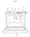
- FIG. 1 is a perspective view of an overheated steam oven, according to an embodiment of the present invention;
- FIG. 2 is a sectional view illustrating an internal construction of the overheated steam oven of FIG. 1;
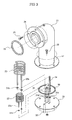
- FIG. 3 is an exploded perspective view illustrating a construction of an overheated steam generator of the overheated steam oven of FIG. 2;
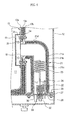
- FIG. 4 is a sectional view illustrating the construction of the overheated steam generator of the overheated steam oven of FIG. 2; and
- FIG. 5 is a top view of the overheated steam oven of FIG. 2.
- Reference will now be made in detail to the embodiments of the present invention, examples of which are illustrated in the accompanying drawings, wherein like reference numerals refer to like elements throughout. The embodiments are described below to explain the present invention by referring to the figures.
- In FIGS. 1 and 2, an overheated or superheated steam oven according to an embodiment of the present invention comprises a
cabinet 10 to define acooking cavity 11 therein, and an overheatedsteam generator 20 mounted to a rear wall in thecabinet 10 to supply overheated steam into thecooking cavity 11. - The
cabinet 10 comprises anouter casing 12, and aninner casing 13 which is installed in theouter casing 12 and spaced apart from theouter casing 12, to define thecooking cavity 11 therein. Thecooking cavity 11 is open at a front thereof to insert and remove foods into and from thecooking cavity 11. Also, theinner casing 13 comprises afirst casing 13a and asecond casing 13b spaced apart from each other to insulate thecooking cavity 11 from an outside of thecooking cavity 11. An insulatingmaterial 13c fills the space between thefirst casing 13a and thesecond casing 13b. That is, walls of thecooking cavity 11 each comprise a multi-layered panel having a plurality of sheets spaced apart from each other, and the insulatingmaterial 13c fills the space between the multi-layered panels. - A
door 14, which is opened downward and closed upward, is attached to the open front of thecabinet 10 to allow a user to open and close thecooking cavity 11. Acontrol unit 15 is provided at a portion of thecabinet 10 above thedoor 14 and comprises adisplay 15a to display an operational state of the overheated steam oven thereon, various kinds ofcontrol buttons 15b, andcontrol switches 15c. - In FIGS. 2 and 3, the overheated
steam generator 20 is provided on the rear wall of thecooking cavity 11, and comprises asteam generating vessel 21 having an outlet connected to asteam inlet port 18 provided on the rear wall of thecooking cavity 11, wherein a predetermined amount of water is contained in thesteam generating vessel 21. The overheated steam generator further comprises afirst heater 22 mounted to a lower portion in thesteam generating vessel 21, and asecond heater 23 mounted to an upper portion in thesteam generating vessel 21. - In FIGS. 3 and 4, the
steam generating vessel 21 comprises a vacuum insulating vessel having a space therein insulated from an outside thereof to minimize heat loss. Thesteam generating vessel 21 further comprises aninner vessel part 21a, and anouter vessel part 21b which surrounds an outer surface of theinner vessel part 21a and is spaced apart from the outer surface of theinner vessel part 21a. A space between theinner vessel part 21a and theouter vessel part 21b comprises ashielding material 21c to intercept radiant heat. The space between theinner vessel part 21a and theouter vessel part 21b is sealed in a vacuum state, once the vacuum state is induced. - The
steam generating vessel 21 further comprises abent part 21d formed by bending an upper end of thesteam generating vessel 21 toward the rear wall of thecooking cavity 11. A front end of the bent part 21dcomprises an outlet of the steam generating vessel 21and is connected to thesteam inlet port 18 provided on the rear wall of thecooking cavity 11. Anupper flange 24 provided around the outlet of thesteam generating vessel 21, is mounted to a predetermined portion of theinner casing 13 around thesteam inlet port 18 by a plurality oflocking members 25, with afirst packing 26 interposed between theupper flange 24 and theinner casing 13 to prevent the leakage of steam. A cover 19having a plurality of steam discharging holes, is mounted to an inner surface of the rear wall of thecooking cavity 11 to allow the overheated steam generated by the overheatedsteam generator 20 to pass into thecooking cavity 11. - The
steam generating vessel 21 further comprises alower flange 27 at a lower end thereof, wherein alower plate 28, which closes an opening of the lower end of thesteam generating vessel 21, is mounted to thelower flange 27 by a plurality oflocking members 29. Asecond packing 30 is interposed between thelower plate 28 and thelower flange 27 to prevent the leakage of water from thesteam generating vessel 21. - The
first heater 22 mounted to the lower portion in thesteam generating vessel 21, and thesecond heater 23 mounted to the upper portion in thesteam generating vessel 21, each comprise a spiral shape to maximize a heat transferring surface area. First andsecond terminals second heaters lower plate 28. Accordingly, the first andsecond heaters lower plate 28. Also, third andfourth packings second terminals second heaters lower plate 28 to prevent the leakage of water from thesteam generating vessel 21. When the predetermined amount of water is fed into thesteam generating vessel 21, thefirst heater 22, provided at the lower portion of thesteam generating vessel 21, is immersed in the water contained in thesteam generating vessel 21, and thesecond heater 23, provided at the upper portion of thesteam generating vessel 21, is located above the water, which is contained in thesteam generating vessel 21 and reaches a maximum water level. Due to the above-mentioned construction, the overheated steam is generated by allowing thesecond heater 23 to further heat the steam generated by an operation of thefirst heater 22 while the steam rises toward the outlet of thesteam generating vessel 21. - Also, a
feed pipe 32 to feed water into thesteam generating vessel 21, adrain pipe 33 to drain the water from thesteam generating vessel 21, and awater level sensor 34 to monitor a level of the water contained in thesteam generating vessel 21, are respectively mounted to thelower plate 28 of thesteam generating vessel 21. Afifth packing 31d is provided between thefeed pipe 32 and thelower plate 28 to prevent the leakage of water from thesteam generating vessel 21. Asixth packing 31c is provided between thewater level sensor 34 and thelower plate 28 to prevent the leakage of water from thesteam generating vessel 21. Thefeed pipe 32 is connected to an external water source (not shown). Thefeed pipe 32 comprises a feed control valve (not shown) to control an amount of water supplied from the external water source (not shown) into thesteam generating vessel 21. The level of the water contained in thesteam generating vessel 21 is maintained by controlling the amount of the water supplied from the external water source (not shown) into thesteam generating vessel 21, in response to a monitoring operation of thewater level sensor 34. In addition, a drain control valve (not shown) is provided on thedrain pipe 33 to drain the residual water from thesteam generating vessel 21 after a cooking operation. - In FIGS. 2 and 5, the overheated steam oven of the present invention further comprises a
discharging port 17 formed on an upper portion of the rear wall of theinner casing 13 to discharge the overheated steam of thecooking cavity 11 after the cooking operation. The overheated steam further oven comprises adischarging pipe 40, having a first end coupled to thedischarging port 17 to communicate with thecooking cavity 11, and a second end which extends to the outside of theouter casing 12. Thedischarging pipe 40 comprises a zigzag-type pattern in a space defined between a top wall of theinner casing 13 and a top wall of theouter casing 12 while extending from thedischarging port 17 to the outside, to increase a heat transfer surface area of thedischarging pipe 40. - Due to the above-mentioned structure of the
discharging pipe 40 with the increased heat transfer surface area, the overheated steam is quickly cooled and condensed into water while passing through thedischarging pipe 40. Therefore, thedischarging pipe 40 operates as a cooling unit or a condensing unit which cools or condenses the overheated steam passing through thedischarging pipe 40. Thedischarging pipe 40 comprises a length which is sufficiently long such that the overheated steam passing through thedischarging pipe 40 is discharged to the outside after most of the steam has condensed into water. - The operation of the overheated steam oven of the present invention will be described herein below.
- First, foods are placed on the cooking trays 16 of the
cooking cavity 11. After, the overheated steam oven is operated and the water is fed into thesteam generating vessel 21 through thefeed pipe 32 of theoverheated steam generator 20. The water level in thesteam generating vessel 21 is then controlled in response to the monitoring operation of thewater level sensor 34. After a predetermined amount of water is fed into thesteam generating vessel 21, the water contained in thesteam generating vessel 21 is heated by thefirst heater 22 to generate steam. Overheated steam is generated by further heating the steam using thesecond heater 23 while the steam rises in thesteam generating vessel 21. The overheated steam is supplied into thecooking cavity 11 through the outlet of thesteam generating vessel 21. And, the foods in thecooking cavity 11 are cooked by the heat of the overheated steam. After cooking is finished, the overheated steam is discharged to the outside of thecooking cavity 11 through the dischargingpipe 40. At this time, the overheated steam passing through the dischargingpipe 40 is condensed into water by the heat transfer between the overheated steam and the outside air, prior to being discharged to the outside. - In the above-mentioned operation, since the
steam generating vessel 21 comprises an insulating construction and the outlet of thesteam generating vessel 21 is mounted to the rear wall of thecooking cavity 11, the overheated steam oven of the present invention generates overheated steam while minimizing heat loss. In addition, since the overheated steam oven of the present invention rapidly supplies overheated steam into thecooking cavity 11, the energy loss is further minimized. Also, since thefirst heater 22, which comprises a spiral shape, is immersed in the water contained in thesteam generating vessel 21, the overheated steam oven of the present invention rapidly boils the water in thesteam generating vessel 21. Also, since thesecond heater 23, which comprises a spiral shape, further heats the steam, the overheated steam oven of the present invention generates the overheated steam within a short period of time while reducing energy requirements. - As apparent from the above description, in an overheated steam oven of the present invention, since an overheated steam generator is mounted on a rear wall of a cooking cavity and the construction of the overheated steam generator is simple in comparison with steam boilers of conventional overheated steam cooking apparatuses, the present invention creates a simplified manufacturing process of the overheated steam oven and a reduction of the manufacturing costs of the overheated steam oven. In addition, the overheated steam oven of the present invention may be used at home by simplifying a construction and reducing a size of the overheated steam oven.
- Also, since a steam generating vessel of the overheated steam generator comprises an insulating construction, the overheated steam oven of the present invention generates overheated steam while minimizing heat loss. Since an outlet of the steam generating vessel is directly connected to the rear wall of the cooking cavity, the overheated steam oven of the present invention rapidly supplies the overheated steam into the cooking cavity.
- Furthermore, since each of walls of the cooking cavity comprises a multi-layered panel having a plurality of sheets spaced apart from each other, the overheated steam oven of the present invention further minimizes heat loss.
- In addition, the overheated steam oven of the present invention comprises an overheated steam discharging structure to discharge the overheated steam to the outside after changing the overheated steam into water, thus preventing the overheated steam from burning a user, thermally deteriorating or damaging items around the overheated steam oven. Furthermore, the overheated steam oven of the present invention reduces a size and noise thereof, since the overheated steam oven does not require any additional air duct or any additional blower.
Claims (13)
- An overheated steam oven, comprising:a cooking cavity (11);an overheated steam generator (20) to supply overheated steam into the cooking cavity (11);an overheated steam discharging unit to discharge the overheated steam from the cooking cavity (11) to an outside of the overheated steam oven; anda condensing unit to condense the overheated steam into water when the overheated steam is discharged from the cooking cavity (11) to the outside, whereby the overheated steam generator (20) comprises:characterised in that the overheated steam generator (20) further comprisesa steam generating vessel (21) having an outlet connected to and communicating with the cooking cavity (11), wherein a predetermined amount of water is contained in the steam generating vessel (21);a first heater (22) to generate steam, and installed in the steam generating vessel (21) to be immersed in the water contained in the steam generating vessel (21);
a second heater (23) mounted to an upper portion in the steam generating vessel (21) to overheat the steam generated by the first heater (22). - The overheated steam oven of claim 1, wherein the overheated steam discharging unit comprises a discharging pipe (40) through which the overheated steam passes, wherein the condensing unit is provided on the discharging pipe (40).
- The overheated steam oven of claim 2, wherein the condensing unit is integrally formed with the discharging pipe (40) and comprises a zigzag-type pattern to increase a heat transfer surface area of the condensing unit.
- The overheated steam oven of any preceding claim, wherein the steam generating vessel (21) comprises an insulating vessel.
- The overheated steam oven of claim 4, wherein the steam generating vessel (21) comprises:an inner vessel part (21a) comprising the first heater (22) and the second heater (23) therein; andan outer vessel part (21b) which surrounds an outer surface of the inner vessel part (21a) and is spaced apart from the outer surface of the inner vessel part (21a), wherein a space between the inner vessel part (21a) and the outer vessel part (21b) is maintained in a vacuum state.
- The overheated steam oven of claim 5, further comprising:a shielding material (21c) filling the space between the inner vessel part (21a) and the outer vessel part (21b) to intercept radiant heat.
- The overheated steam oven of any preceding claim, wherein the first heater (22) and the second heater (23) each comprise a spiral shape.
- The overheated steam oven of any preceding claim, further comprising:a water level sensor (34) installed in the steam generating vessel (21) to monitor a level of the water contained in the steam generating vessel (21).
- The overheated steam oven of any preceding claim, wherein walls of the cooking cavity (11) each comprise a multi-layered panel having a plurality of sheets spaced apart from each other to insulate the cooking cavity (11).
- The overheated steam oven of any preceding claim, further comprising a steam inlet port (18) provided on a rear wall of the cooking cavity (11), wherein the overheated steam generator (20) is provided at a rear wall of the cooking cavity (11) and comprises a steam generating vessel (21) having an outlet connected to the steam inlet port (18).
- The overheated steam oven of any preceding claim, further comprising:a feed pipe (32) to feed water into the steam generating vessel (21); anda drain pipe (33) to drain the water from the steam generating vessel (21).
- The overheated steam oven of any preceding claim, further comprising a discharging port (17), wherein a first end of the discharging pipe (40) is coupled to the discharging port (17) to communicate with the cooking cavity (11) and a second end extends to the outside of the cooking cavity (11).
- The overheated steam oven of claim 12, wherein the discharging pipe (40) is of a predetermined length to allow the overheated steam passing through the discharging pipe (40) to be discharged to the outside after the overheated steam is condensed into water.
Applications Claiming Priority (2)
| Application Number | Priority Date | Filing Date | Title |
|---|---|---|---|
| KR1020030085931A KR20050052083A (en) | 2003-11-29 | 2003-11-29 | Superheated steam cooking apparatus |
| KR2003085931 | 2003-11-29 |
Publications (2)
| Publication Number | Publication Date |
|---|---|
| EP1535549A1 EP1535549A1 (en) | 2005-06-01 |
| EP1535549B1 true EP1535549B1 (en) | 2006-12-06 |
Family
ID=34464776
Family Applications (1)
| Application Number | Title | Priority Date | Filing Date |
|---|---|---|---|
| EP04253312A Expired - Lifetime EP1535549B1 (en) | 2003-11-29 | 2004-06-03 | Overheated steam oven |
Country Status (5)
| Country | Link |
|---|---|
| US (1) | US7143761B2 (en) |
| EP (1) | EP1535549B1 (en) |
| KR (1) | KR20050052083A (en) |
| CN (1) | CN1283199C (en) |
| DE (1) | DE602004003545T2 (en) |
Families Citing this family (25)
| Publication number | Priority date | Publication date | Assignee | Title |
|---|---|---|---|---|
| KR20050056056A (en) * | 2003-12-09 | 2005-06-14 | 삼성전자주식회사 | Superheated steam cooking apparatus |
| KR100715042B1 (en) * | 2005-06-10 | 2007-05-09 | 삼성전자주식회사 | A heating cooker |
| EP1811274A1 (en) * | 2006-01-19 | 2007-07-25 | Whirlpool Corporation | Water level measurement system |
| US7282674B2 (en) * | 2006-02-17 | 2007-10-16 | Alto-Shaam, Inc. | System and method for limiting the escape of heat and steam from an open oven door |
| RU2401040C1 (en) * | 2006-08-29 | 2010-10-10 | Канг-Су ПАК | Device for steam cooking |
| KR100824006B1 (en) * | 2006-12-29 | 2008-04-24 | 엘지전자 주식회사 | Steam generating device for steam oven |
| AU2007361169A1 (en) | 2007-11-16 | 2009-05-22 | Fiesta Gas Grills Llc | Temperature control apparatus for a barbeque grill |
| US9289096B2 (en) * | 2007-11-16 | 2016-03-22 | Wolfedale Engineering Limited | Temperature control device and method |
| CN102771523B (en) | 2008-01-28 | 2015-04-22 | 杜克制造公司 | Convection oven |
| DE202009003296U1 (en) * | 2009-03-06 | 2009-05-28 | Eloma Gmbh | Gargerätekombination |
| BR112012027798A2 (en) * | 2010-04-28 | 2016-08-09 | Sharp Kk | cooking device |
| KR101634872B1 (en) * | 2013-12-03 | 2016-06-29 | 정규태 | cooking utensils using steams |
| GB2525146B (en) * | 2014-01-17 | 2017-01-11 | Spirax-Sarco Ltd | A steam oven installation |
| CN104814664B (en) * | 2015-04-08 | 2017-06-16 | 宁波方太厨具有限公司 | A kind of minute-pressure electricity steam box quick pressure releasing heat sink |
| US10429082B2 (en) * | 2015-07-08 | 2019-10-01 | Tomoda Selling & Sailing Co., Ltd. | Heating cooking device and heating cooking method using superheated vapor |
| CN105147052B (en) * | 2015-08-07 | 2017-07-04 | 广东美的厨房电器制造有限公司 | For the control method and steam cooking apparatus of steam cooking apparatus |
| WO2017111538A1 (en) * | 2015-12-24 | 2017-06-29 | 정규태 | Steam cooking vessel |
| WO2017116352A1 (en) * | 2015-12-29 | 2017-07-06 | Arcelik Anonim Sirketi | An oven comprising a water tank |
| CN107157312A (en) * | 2017-06-26 | 2017-09-15 | 广东美的厨房电器制造有限公司 | Steam cooking apparatus |
| CN107242776A (en) * | 2017-06-26 | 2017-10-13 | 广东美的厨房电器制造有限公司 | Steam cooking apparatus |
| CN107242775A (en) * | 2017-06-26 | 2017-10-13 | 广东美的厨房电器制造有限公司 | Steam cooking apparatus |
| CN107242777A (en) * | 2017-06-26 | 2017-10-13 | 广东美的厨房电器制造有限公司 | Steam cooking apparatus |
| CN111110016B (en) * | 2019-12-30 | 2021-05-11 | 广东美的厨房电器制造有限公司 | Steaming and baking equipment, humidity detection method and humidity control method |
| CN111772473B (en) * | 2020-07-11 | 2021-06-08 | 广东威林科技股份有限公司 | Steam oven |
| CN113576271B (en) * | 2021-08-27 | 2022-05-31 | 广东美的厨房电器制造有限公司 | Cooking utensil |
Family Cites Families (21)
| Publication number | Priority date | Publication date | Assignee | Title |
|---|---|---|---|---|
| US3604895A (en) * | 1969-10-28 | 1971-09-14 | Lincoln Mfg Co | Electrically heated steam treatment device |
| US4173215A (en) * | 1977-12-05 | 1979-11-06 | Mscan Metal Canada Limitee | Apparatus for steaming foods |
| CH662924A5 (en) * | 1985-01-21 | 1987-11-13 | Wuest Ernst Menu System | DAMPER. |
| DE3700532A1 (en) * | 1986-08-12 | 1988-07-21 | Ernst Kirchhoff | Apparatus for reheating and/or final baking of foods |
| IT1234689B (en) * | 1989-03-21 | 1992-05-26 | Zanussi Grandi Impianti Spa | FORCED CONVECTION COOKING OVEN |
| US5158064A (en) * | 1991-05-13 | 1992-10-27 | Willis Thomas J | Steam drying element for steam cooking device |
| FR2711229B1 (en) * | 1993-10-12 | 1995-12-08 | Bourgeois Ste Coop Prod | Steam oven fitted with a steam evacuation device. |
| KR0147884B1 (en) * | 1993-11-11 | 1998-08-17 | 모리시타 요이찌 | Heating cooker |
| JPH08128639A (en) | 1994-10-31 | 1996-05-21 | Sanden Corp | Cooker |
| US5549038A (en) * | 1995-11-16 | 1996-08-27 | Market Forge Industries | Modulated steam cooker |
| FR2750027B1 (en) * | 1996-06-21 | 1999-03-05 | Moulinex Sa | DEVICE FOR CONDENSING COOKING VAPORS AND COOKING APPLIANCE COMPRISING SUCH A DEVICE |
| US5715745A (en) * | 1997-04-11 | 1998-02-10 | Food Service Supplies, Inc. | Humidified and heated cabinet for storing food |
| JP3408137B2 (en) * | 1998-02-27 | 2003-05-19 | 三洋電機株式会社 | Cooking device |
| KR100463074B1 (en) * | 1999-07-21 | 2004-12-23 | 오노 쇼꾜잉 고교 가부시키가이샤 | Heating, cooking, and disinfecting apparatus |
| JP2001263667A (en) * | 2000-03-21 | 2001-09-26 | Matsushita Electric Ind Co Ltd | Superheated cooking apparatus |
| JP2001355844A (en) * | 2000-06-16 | 2001-12-26 | Matsushita Electric Ind Co Ltd | Cooker |
| JP2002071138A (en) * | 2000-08-28 | 2002-03-08 | Johnson Boiler Kk | Cooking oven |
| JP3973479B2 (en) * | 2002-04-24 | 2007-09-12 | シャープ株式会社 | Cooker |
| JP2003336846A (en) * | 2002-05-15 | 2003-11-28 | Matsushita Electric Ind Co Ltd | Heating cooking apparatus |
| KR100531978B1 (en) * | 2003-07-08 | 2005-12-05 | 김현동 | The steamer with drain structure of inner |
| KR20050027460A (en) * | 2003-09-15 | 2005-03-21 | 삼성전자주식회사 | Superheated steam cooking apparatus and control method thereof |
-
2003
- 2003-11-29 KR KR1020030085931A patent/KR20050052083A/en not_active Application Discontinuation
-
2004
- 2004-05-13 US US10/844,514 patent/US7143761B2/en not_active Expired - Fee Related
- 2004-06-02 CN CNB2004100492017A patent/CN1283199C/en not_active Expired - Fee Related
- 2004-06-03 DE DE602004003545T patent/DE602004003545T2/en not_active Expired - Lifetime
- 2004-06-03 EP EP04253312A patent/EP1535549B1/en not_active Expired - Lifetime
Also Published As
| Publication number | Publication date |
|---|---|
| EP1535549A1 (en) | 2005-06-01 |
| US20050115559A1 (en) | 2005-06-02 |
| US7143761B2 (en) | 2006-12-05 |
| CN1283199C (en) | 2006-11-08 |
| DE602004003545D1 (en) | 2007-01-18 |
| CN1620974A (en) | 2005-06-01 |
| KR20050052083A (en) | 2005-06-02 |
| DE602004003545T2 (en) | 2007-10-11 |
Similar Documents
| Publication | Publication Date | Title |
|---|---|---|
| EP1535549B1 (en) | Overheated steam oven | |
| US7049550B2 (en) | Overheated steam oven | |
| US6911626B2 (en) | Overheated steam oven | |
| US6906291B2 (en) | Overheated steam oven | |
| US7341055B2 (en) | Overheated steam oven | |
| EP1517092A1 (en) | Overheated steam oven and method of controlling the same | |
| EP1905330B1 (en) | Steam generator and heating cooking apparatus having the same | |
| EP1617148A1 (en) | Heating apparatus for cooking | |
| JP4051384B2 (en) | Superheated steam cooker | |
| US6992268B2 (en) | Steam oven having an inner casing including a vacuum | |
| KR100715042B1 (en) | A heating cooker | |
| US7093592B2 (en) | Steam oven | |
| JP4000531B2 (en) | Cooker | |
| KR100526210B1 (en) | Steam cooking apparatus | |
| KR100634789B1 (en) | Heating cooker | |
| JP6158098B2 (en) | Cooker | |
| KR100780335B1 (en) | Heating cooker | |
| JP2018159509A (en) | Heating cooker |
Legal Events
| Date | Code | Title | Description |
|---|---|---|---|
| PUAI | Public reference made under article 153(3) epc to a published international application that has entered the european phase |
Free format text: ORIGINAL CODE: 0009012 |
|
| AK | Designated contracting states |
Kind code of ref document: A1 Designated state(s): AT BE BG CH CY CZ DE DK EE ES FI FR GB GR HU IE IT LI LU MC NL PL PT RO SE SI SK TR |
|
| AX | Request for extension of the european patent |
Extension state: AL HR LT LV MK |
|
| 17P | Request for examination filed |
Effective date: 20051014 |
|
| AKX | Designation fees paid |
Designated state(s): DE FR GB |
|
| GRAP | Despatch of communication of intention to grant a patent |
Free format text: ORIGINAL CODE: EPIDOSNIGR1 |
|
| GRAS | Grant fee paid |
Free format text: ORIGINAL CODE: EPIDOSNIGR3 |
|
| GRAA | (expected) grant |
Free format text: ORIGINAL CODE: 0009210 |
|
| AK | Designated contracting states |
Kind code of ref document: B1 Designated state(s): DE FR GB |
|
| REG | Reference to a national code |
Ref country code: GB Ref legal event code: FG4D |
|
| REF | Corresponds to: |
Ref document number: 602004003545 Country of ref document: DE Date of ref document: 20070118 Kind code of ref document: P |
|
| ET | Fr: translation filed | ||
| PLBE | No opposition filed within time limit |
Free format text: ORIGINAL CODE: 0009261 |
|
| STAA | Information on the status of an ep patent application or granted ep patent |
Free format text: STATUS: NO OPPOSITION FILED WITHIN TIME LIMIT |
|
| 26N | No opposition filed |
Effective date: 20070907 |
|
| REG | Reference to a national code |
Ref country code: FR Ref legal event code: PLFP Year of fee payment: 13 |
|
| REG | Reference to a national code |
Ref country code: FR Ref legal event code: PLFP Year of fee payment: 14 |
|
| PGFP | Annual fee paid to national office [announced via postgrant information from national office to epo] |
Ref country code: FR Payment date: 20170524 Year of fee payment: 14 Ref country code: GB Payment date: 20170522 Year of fee payment: 14 |
|
| REG | Reference to a national code |
Ref country code: DE Ref legal event code: R082 Ref document number: 602004003545 Country of ref document: DE Representative=s name: WUNDERLICH & HEIM PATENTANWAELTE PARTNERSCHAFT, DE |
|
| PGFP | Annual fee paid to national office [announced via postgrant information from national office to epo] |
Ref country code: DE Payment date: 20180522 Year of fee payment: 15 |
|
| GBPC | Gb: european patent ceased through non-payment of renewal fee |
Effective date: 20180603 |
|
| PG25 | Lapsed in a contracting state [announced via postgrant information from national office to epo] |
Ref country code: GB Free format text: LAPSE BECAUSE OF NON-PAYMENT OF DUE FEES Effective date: 20180603 Ref country code: FR Free format text: LAPSE BECAUSE OF NON-PAYMENT OF DUE FEES Effective date: 20180630 |
|
| REG | Reference to a national code |
Ref country code: DE Ref legal event code: R119 Ref document number: 602004003545 Country of ref document: DE |
|
| PG25 | Lapsed in a contracting state [announced via postgrant information from national office to epo] |
Ref country code: DE Free format text: LAPSE BECAUSE OF NON-PAYMENT OF DUE FEES Effective date: 20200101 |