EP1535299B1 - Weiss-led-scheinwerfer - Google Patents
Weiss-led-scheinwerfer Download PDFInfo
- Publication number
- EP1535299B1 EP1535299B1 EP03764747A EP03764747A EP1535299B1 EP 1535299 B1 EP1535299 B1 EP 1535299B1 EP 03764747 A EP03764747 A EP 03764747A EP 03764747 A EP03764747 A EP 03764747A EP 1535299 B1 EP1535299 B1 EP 1535299B1
- Authority
- EP
- European Patent Office
- Prior art keywords
- light
- led
- vehicle headlight
- headlight according
- lens
- Prior art date
- Legal status (The legal status is an assumption and is not a legal conclusion. Google has not performed a legal analysis and makes no representation as to the accuracy of the status listed.)
- Expired - Lifetime
Links
- 239000004065 semiconductor Substances 0.000 claims abstract description 27
- 229910000679 solder Inorganic materials 0.000 claims abstract description 23
- 239000000758 substrate Substances 0.000 claims abstract description 13
- 238000005516 engineering process Methods 0.000 claims abstract description 7
- OAICVXFJPJFONN-UHFFFAOYSA-N Phosphorus Chemical compound [P] OAICVXFJPJFONN-UHFFFAOYSA-N 0.000 claims description 16
- 230000003287 optical effect Effects 0.000 claims description 8
- 238000002347 injection Methods 0.000 claims description 6
- 239000007924 injection Substances 0.000 claims description 6
- 238000001746 injection moulding Methods 0.000 claims description 5
- QLJCFNUYUJEXET-UHFFFAOYSA-K aluminum;trinitrite Chemical compound [Al+3].[O-]N=O.[O-]N=O.[O-]N=O QLJCFNUYUJEXET-UHFFFAOYSA-K 0.000 claims description 3
- 238000001816 cooling Methods 0.000 claims description 3
- 229910052802 copper Inorganic materials 0.000 claims description 3
- 239000010949 copper Substances 0.000 claims description 3
- RYGMFSIKBFXOCR-UHFFFAOYSA-N Copper Chemical compound [Cu] RYGMFSIKBFXOCR-UHFFFAOYSA-N 0.000 claims description 2
- 239000004593 Epoxy Substances 0.000 claims description 2
- XUIMIQQOPSSXEZ-UHFFFAOYSA-N Silicon Chemical compound [Si] XUIMIQQOPSSXEZ-UHFFFAOYSA-N 0.000 claims description 2
- 239000004020 conductor Substances 0.000 claims description 2
- 230000007246 mechanism Effects 0.000 claims description 2
- 229910052751 metal Inorganic materials 0.000 claims description 2
- 239000002184 metal Substances 0.000 claims description 2
- 230000007935 neutral effect Effects 0.000 claims description 2
- 230000001681 protective effect Effects 0.000 claims description 2
- 229910052710 silicon Inorganic materials 0.000 claims description 2
- 239000010703 silicon Substances 0.000 claims description 2
- 239000007787 solid Substances 0.000 claims description 2
- 239000000463 material Substances 0.000 description 13
- 230000008901 benefit Effects 0.000 description 6
- 239000010931 gold Substances 0.000 description 4
- 238000000034 method Methods 0.000 description 4
- BQCADISMDOOEFD-UHFFFAOYSA-N Silver Chemical compound [Ag] BQCADISMDOOEFD-UHFFFAOYSA-N 0.000 description 3
- 238000005286 illumination Methods 0.000 description 3
- 238000001465 metallisation Methods 0.000 description 3
- 239000004033 plastic Substances 0.000 description 3
- 229910052709 silver Inorganic materials 0.000 description 3
- 239000004332 silver Substances 0.000 description 3
- 229910052782 aluminium Inorganic materials 0.000 description 2
- XAGFODPZIPBFFR-UHFFFAOYSA-N aluminium Chemical compound [Al] XAGFODPZIPBFFR-UHFFFAOYSA-N 0.000 description 2
- 230000008030 elimination Effects 0.000 description 2
- 238000003379 elimination reaction Methods 0.000 description 2
- PCHJSUWPFVWCPO-UHFFFAOYSA-N gold Chemical compound [Au] PCHJSUWPFVWCPO-UHFFFAOYSA-N 0.000 description 2
- 229910052737 gold Inorganic materials 0.000 description 2
- 230000009467 reduction Effects 0.000 description 2
- 238000007789 sealing Methods 0.000 description 2
- QCEUXSAXTBNJGO-UHFFFAOYSA-N [Ag].[Sn] Chemical compound [Ag].[Sn] QCEUXSAXTBNJGO-UHFFFAOYSA-N 0.000 description 1
- 230000002411 adverse Effects 0.000 description 1
- JNDMLEXHDPKVFC-UHFFFAOYSA-N aluminum;oxygen(2-);yttrium(3+) Chemical compound [O-2].[O-2].[O-2].[Al+3].[Y+3] JNDMLEXHDPKVFC-UHFFFAOYSA-N 0.000 description 1
- 230000000712 assembly Effects 0.000 description 1
- 238000000429 assembly Methods 0.000 description 1
- 239000011230 binding agent Substances 0.000 description 1
- 230000033228 biological regulation Effects 0.000 description 1
- 239000003086 colorant Substances 0.000 description 1
- 230000008878 coupling Effects 0.000 description 1
- 238000010168 coupling process Methods 0.000 description 1
- 238000005859 coupling reaction Methods 0.000 description 1
- 230000007423 decrease Effects 0.000 description 1
- 230000005611 electricity Effects 0.000 description 1
- 239000010437 gem Substances 0.000 description 1
- 239000011521 glass Substances 0.000 description 1
- 239000003292 glue Substances 0.000 description 1
- 229910052736 halogen Inorganic materials 0.000 description 1
- 150000002367 halogens Chemical class 0.000 description 1
- 238000009434 installation Methods 0.000 description 1
- LQBJWKCYZGMFEV-UHFFFAOYSA-N lead tin Chemical compound [Sn].[Pb] LQBJWKCYZGMFEV-UHFFFAOYSA-N 0.000 description 1
- 238000004519 manufacturing process Methods 0.000 description 1
- 239000011159 matrix material Substances 0.000 description 1
- 230000004048 modification Effects 0.000 description 1
- 238000012986 modification Methods 0.000 description 1
- 238000000465 moulding Methods 0.000 description 1
- 229910052754 neon Inorganic materials 0.000 description 1
- GKAOGPIIYCISHV-UHFFFAOYSA-N neon atom Chemical compound [Ne] GKAOGPIIYCISHV-UHFFFAOYSA-N 0.000 description 1
- 238000007639 printing Methods 0.000 description 1
- 230000001105 regulatory effect Effects 0.000 description 1
- 230000003252 repetitive effect Effects 0.000 description 1
- 230000004044 response Effects 0.000 description 1
- 239000000565 sealant Substances 0.000 description 1
- 238000007493 shaping process Methods 0.000 description 1
- 238000005476 soldering Methods 0.000 description 1
- 230000008646 thermal stress Effects 0.000 description 1
- 230000007704 transition Effects 0.000 description 1
- 229910052724 xenon Inorganic materials 0.000 description 1
- FHNFHKCVQCLJFQ-UHFFFAOYSA-N xenon atom Chemical compound [Xe] FHNFHKCVQCLJFQ-UHFFFAOYSA-N 0.000 description 1
- 229910019901 yttrium aluminum garnet Inorganic materials 0.000 description 1
Images


Classifications
-
- B—PERFORMING OPERATIONS; TRANSPORTING
- B60—VEHICLES IN GENERAL
- B60Q—ARRANGEMENT OF SIGNALLING OR LIGHTING DEVICES, THE MOUNTING OR SUPPORTING THEREOF OR CIRCUITS THEREFOR, FOR VEHICLES IN GENERAL
- B60Q1/00—Arrangement of optical signalling or lighting devices, the mounting or supporting thereof or circuits therefor
- B60Q1/02—Arrangement of optical signalling or lighting devices, the mounting or supporting thereof or circuits therefor the devices being primarily intended to illuminate the way ahead or to illuminate other areas of way or environments
- B60Q1/04—Arrangement of optical signalling or lighting devices, the mounting or supporting thereof or circuits therefor the devices being primarily intended to illuminate the way ahead or to illuminate other areas of way or environments the devices being headlights
-
- F—MECHANICAL ENGINEERING; LIGHTING; HEATING; WEAPONS; BLASTING
- F21—LIGHTING
- F21V—FUNCTIONAL FEATURES OR DETAILS OF LIGHTING DEVICES OR SYSTEMS THEREOF; STRUCTURAL COMBINATIONS OF LIGHTING DEVICES WITH OTHER ARTICLES, NOT OTHERWISE PROVIDED FOR
- F21V29/00—Protecting lighting devices from thermal damage; Cooling or heating arrangements specially adapted for lighting devices or systems
- F21V29/50—Cooling arrangements
- F21V29/51—Cooling arrangements using condensation or evaporation of a fluid, e.g. heat pipes
-
- B—PERFORMING OPERATIONS; TRANSPORTING
- B60—VEHICLES IN GENERAL
- B60Q—ARRANGEMENT OF SIGNALLING OR LIGHTING DEVICES, THE MOUNTING OR SUPPORTING THEREOF OR CIRCUITS THEREFOR, FOR VEHICLES IN GENERAL
- B60Q1/00—Arrangement of optical signalling or lighting devices, the mounting or supporting thereof or circuits therefor
- B60Q1/02—Arrangement of optical signalling or lighting devices, the mounting or supporting thereof or circuits therefor the devices being primarily intended to illuminate the way ahead or to illuminate other areas of way or environments
- B60Q1/04—Arrangement of optical signalling or lighting devices, the mounting or supporting thereof or circuits therefor the devices being primarily intended to illuminate the way ahead or to illuminate other areas of way or environments the devices being headlights
- B60Q1/06—Arrangement of optical signalling or lighting devices, the mounting or supporting thereof or circuits therefor the devices being primarily intended to illuminate the way ahead or to illuminate other areas of way or environments the devices being headlights adjustable, e.g. remotely-controlled from inside vehicle
- B60Q1/068—Arrangement of optical signalling or lighting devices, the mounting or supporting thereof or circuits therefor the devices being primarily intended to illuminate the way ahead or to illuminate other areas of way or environments the devices being headlights adjustable, e.g. remotely-controlled from inside vehicle by mechanical means
- B60Q1/072—Arrangement of optical signalling or lighting devices, the mounting or supporting thereof or circuits therefor the devices being primarily intended to illuminate the way ahead or to illuminate other areas of way or environments the devices being headlights adjustable, e.g. remotely-controlled from inside vehicle by mechanical means comprising a flexible element, e.g. chain
-
- F—MECHANICAL ENGINEERING; LIGHTING; HEATING; WEAPONS; BLASTING
- F21—LIGHTING
- F21S—NON-PORTABLE LIGHTING DEVICES; SYSTEMS THEREOF; VEHICLE LIGHTING DEVICES SPECIALLY ADAPTED FOR VEHICLE EXTERIORS
- F21S41/00—Illuminating devices specially adapted for vehicle exteriors, e.g. headlamps
- F21S41/10—Illuminating devices specially adapted for vehicle exteriors, e.g. headlamps characterised by the light source
- F21S41/14—Illuminating devices specially adapted for vehicle exteriors, e.g. headlamps characterised by the light source characterised by the type of light source
- F21S41/141—Light emitting diodes [LED]
- F21S41/143—Light emitting diodes [LED] the main emission direction of the LED being parallel to the optical axis of the illuminating device
-
- F—MECHANICAL ENGINEERING; LIGHTING; HEATING; WEAPONS; BLASTING
- F21—LIGHTING
- F21S—NON-PORTABLE LIGHTING DEVICES; SYSTEMS THEREOF; VEHICLE LIGHTING DEVICES SPECIALLY ADAPTED FOR VEHICLE EXTERIORS
- F21S41/00—Illuminating devices specially adapted for vehicle exteriors, e.g. headlamps
- F21S41/10—Illuminating devices specially adapted for vehicle exteriors, e.g. headlamps characterised by the light source
- F21S41/14—Illuminating devices specially adapted for vehicle exteriors, e.g. headlamps characterised by the light source characterised by the type of light source
- F21S41/141—Light emitting diodes [LED]
- F21S41/151—Light emitting diodes [LED] arranged in one or more lines
-
- F—MECHANICAL ENGINEERING; LIGHTING; HEATING; WEAPONS; BLASTING
- F21—LIGHTING
- F21S—NON-PORTABLE LIGHTING DEVICES; SYSTEMS THEREOF; VEHICLE LIGHTING DEVICES SPECIALLY ADAPTED FOR VEHICLE EXTERIORS
- F21S41/00—Illuminating devices specially adapted for vehicle exteriors, e.g. headlamps
- F21S41/10—Illuminating devices specially adapted for vehicle exteriors, e.g. headlamps characterised by the light source
- F21S41/14—Illuminating devices specially adapted for vehicle exteriors, e.g. headlamps characterised by the light source characterised by the type of light source
- F21S41/141—Light emitting diodes [LED]
- F21S41/155—Surface emitters, e.g. organic light emitting diodes [OLED]
-
- F—MECHANICAL ENGINEERING; LIGHTING; HEATING; WEAPONS; BLASTING
- F21—LIGHTING
- F21S—NON-PORTABLE LIGHTING DEVICES; SYSTEMS THEREOF; VEHICLE LIGHTING DEVICES SPECIALLY ADAPTED FOR VEHICLE EXTERIORS
- F21S41/00—Illuminating devices specially adapted for vehicle exteriors, e.g. headlamps
- F21S41/20—Illuminating devices specially adapted for vehicle exteriors, e.g. headlamps characterised by refractors, transparent cover plates, light guides or filters
- F21S41/24—Light guides
-
- F—MECHANICAL ENGINEERING; LIGHTING; HEATING; WEAPONS; BLASTING
- F21—LIGHTING
- F21S—NON-PORTABLE LIGHTING DEVICES; SYSTEMS THEREOF; VEHICLE LIGHTING DEVICES SPECIALLY ADAPTED FOR VEHICLE EXTERIORS
- F21S41/00—Illuminating devices specially adapted for vehicle exteriors, e.g. headlamps
- F21S41/60—Illuminating devices specially adapted for vehicle exteriors, e.g. headlamps characterised by a variable light distribution
- F21S41/65—Illuminating devices specially adapted for vehicle exteriors, e.g. headlamps characterised by a variable light distribution by acting on light sources
- F21S41/663—Illuminating devices specially adapted for vehicle exteriors, e.g. headlamps characterised by a variable light distribution by acting on light sources by switching light sources
-
- F—MECHANICAL ENGINEERING; LIGHTING; HEATING; WEAPONS; BLASTING
- F21—LIGHTING
- F21V—FUNCTIONAL FEATURES OR DETAILS OF LIGHTING DEVICES OR SYSTEMS THEREOF; STRUCTURAL COMBINATIONS OF LIGHTING DEVICES WITH OTHER ARTICLES, NOT OTHERWISE PROVIDED FOR
- F21V29/00—Protecting lighting devices from thermal damage; Cooling or heating arrangements specially adapted for lighting devices or systems
- F21V29/50—Cooling arrangements
- F21V29/70—Cooling arrangements characterised by passive heat-dissipating elements, e.g. heat-sinks
- F21V29/74—Cooling arrangements characterised by passive heat-dissipating elements, e.g. heat-sinks with fins or blades
- F21V29/75—Cooling arrangements characterised by passive heat-dissipating elements, e.g. heat-sinks with fins or blades with fins or blades having different shapes, thicknesses or spacing
-
- F—MECHANICAL ENGINEERING; LIGHTING; HEATING; WEAPONS; BLASTING
- F21—LIGHTING
- F21V—FUNCTIONAL FEATURES OR DETAILS OF LIGHTING DEVICES OR SYSTEMS THEREOF; STRUCTURAL COMBINATIONS OF LIGHTING DEVICES WITH OTHER ARTICLES, NOT OTHERWISE PROVIDED FOR
- F21V29/00—Protecting lighting devices from thermal damage; Cooling or heating arrangements specially adapted for lighting devices or systems
- F21V29/50—Cooling arrangements
- F21V29/70—Cooling arrangements characterised by passive heat-dissipating elements, e.g. heat-sinks
- F21V29/74—Cooling arrangements characterised by passive heat-dissipating elements, e.g. heat-sinks with fins or blades
- F21V29/76—Cooling arrangements characterised by passive heat-dissipating elements, e.g. heat-sinks with fins or blades with essentially identical parallel planar fins or blades, e.g. with comb-like cross-section
- F21V29/763—Cooling arrangements characterised by passive heat-dissipating elements, e.g. heat-sinks with fins or blades with essentially identical parallel planar fins or blades, e.g. with comb-like cross-section the planes containing the fins or blades having the direction of the light emitting axis
-
- G—PHYSICS
- G02—OPTICS
- G02B—OPTICAL ELEMENTS, SYSTEMS OR APPARATUS
- G02B19/00—Condensers, e.g. light collectors or similar non-imaging optics
- G02B19/0004—Condensers, e.g. light collectors or similar non-imaging optics characterised by the optical means employed
- G02B19/0028—Condensers, e.g. light collectors or similar non-imaging optics characterised by the optical means employed refractive and reflective surfaces, e.g. non-imaging catadioptric systems
-
- G—PHYSICS
- G02—OPTICS
- G02B—OPTICAL ELEMENTS, SYSTEMS OR APPARATUS
- G02B19/00—Condensers, e.g. light collectors or similar non-imaging optics
- G02B19/0033—Condensers, e.g. light collectors or similar non-imaging optics characterised by the use
- G02B19/0047—Condensers, e.g. light collectors or similar non-imaging optics characterised by the use for use with a light source
- G02B19/0061—Condensers, e.g. light collectors or similar non-imaging optics characterised by the use for use with a light source the light source comprising a LED
- G02B19/0066—Condensers, e.g. light collectors or similar non-imaging optics characterised by the use for use with a light source the light source comprising a LED in the form of an LED array
-
- G—PHYSICS
- G02—OPTICS
- G02B—OPTICAL ELEMENTS, SYSTEMS OR APPARATUS
- G02B6/00—Light guides; Structural details of arrangements comprising light guides and other optical elements, e.g. couplings
- G02B6/0001—Light guides; Structural details of arrangements comprising light guides and other optical elements, e.g. couplings specially adapted for lighting devices or systems
- G02B6/0011—Light guides; Structural details of arrangements comprising light guides and other optical elements, e.g. couplings specially adapted for lighting devices or systems the light guides being planar or of plate-like form
- G02B6/0013—Means for improving the coupling-in of light from the light source into the light guide
- G02B6/0015—Means for improving the coupling-in of light from the light source into the light guide provided on the surface of the light guide or in the bulk of it
- G02B6/0018—Redirecting means on the surface of the light guide
-
- G—PHYSICS
- G02—OPTICS
- G02B—OPTICAL ELEMENTS, SYSTEMS OR APPARATUS
- G02B6/00—Light guides; Structural details of arrangements comprising light guides and other optical elements, e.g. couplings
- G02B6/0001—Light guides; Structural details of arrangements comprising light guides and other optical elements, e.g. couplings specially adapted for lighting devices or systems
- G02B6/0011—Light guides; Structural details of arrangements comprising light guides and other optical elements, e.g. couplings specially adapted for lighting devices or systems the light guides being planar or of plate-like form
- G02B6/0013—Means for improving the coupling-in of light from the light source into the light guide
- G02B6/0015—Means for improving the coupling-in of light from the light source into the light guide provided on the surface of the light guide or in the bulk of it
- G02B6/002—Means for improving the coupling-in of light from the light source into the light guide provided on the surface of the light guide or in the bulk of it by shaping at least a portion of the light guide, e.g. with collimating, focussing or diverging surfaces
-
- F—MECHANICAL ENGINEERING; LIGHTING; HEATING; WEAPONS; BLASTING
- F21—LIGHTING
- F21S—NON-PORTABLE LIGHTING DEVICES; SYSTEMS THEREOF; VEHICLE LIGHTING DEVICES SPECIALLY ADAPTED FOR VEHICLE EXTERIORS
- F21S41/00—Illuminating devices specially adapted for vehicle exteriors, e.g. headlamps
- F21S41/10—Illuminating devices specially adapted for vehicle exteriors, e.g. headlamps characterised by the light source
- F21S41/19—Attachment of light sources or lamp holders
-
- F—MECHANICAL ENGINEERING; LIGHTING; HEATING; WEAPONS; BLASTING
- F21—LIGHTING
- F21S—NON-PORTABLE LIGHTING DEVICES; SYSTEMS THEREOF; VEHICLE LIGHTING DEVICES SPECIALLY ADAPTED FOR VEHICLE EXTERIORS
- F21S41/00—Illuminating devices specially adapted for vehicle exteriors, e.g. headlamps
- F21S41/30—Illuminating devices specially adapted for vehicle exteriors, e.g. headlamps characterised by reflectors
- F21S41/32—Optical layout thereof
- F21S41/323—Optical layout thereof the reflector having two perpendicular cross sections having regular geometrical curves of a distinct nature
-
- F—MECHANICAL ENGINEERING; LIGHTING; HEATING; WEAPONS; BLASTING
- F21—LIGHTING
- F21S—NON-PORTABLE LIGHTING DEVICES; SYSTEMS THEREOF; VEHICLE LIGHTING DEVICES SPECIALLY ADAPTED FOR VEHICLE EXTERIORS
- F21S41/00—Illuminating devices specially adapted for vehicle exteriors, e.g. headlamps
- F21S41/30—Illuminating devices specially adapted for vehicle exteriors, e.g. headlamps characterised by reflectors
- F21S41/32—Optical layout thereof
- F21S41/36—Combinations of two or more separate reflectors
- F21S41/365—Combinations of two or more separate reflectors successively reflecting the light
-
- F—MECHANICAL ENGINEERING; LIGHTING; HEATING; WEAPONS; BLASTING
- F21—LIGHTING
- F21S—NON-PORTABLE LIGHTING DEVICES; SYSTEMS THEREOF; VEHICLE LIGHTING DEVICES SPECIALLY ADAPTED FOR VEHICLE EXTERIORS
- F21S45/00—Arrangements within vehicle lighting devices specially adapted for vehicle exteriors, for purposes other than emission or distribution of light
- F21S45/40—Cooling of lighting devices
- F21S45/47—Passive cooling, e.g. using fins, thermal conductive elements or openings
- F21S45/48—Passive cooling, e.g. using fins, thermal conductive elements or openings with means for conducting heat from the inside to the outside of the lighting devices, e.g. with fins on the outer surface of the lighting device
-
- F—MECHANICAL ENGINEERING; LIGHTING; HEATING; WEAPONS; BLASTING
- F21—LIGHTING
- F21Y—INDEXING SCHEME ASSOCIATED WITH SUBCLASSES F21K, F21L, F21S and F21V, RELATING TO THE FORM OR THE KIND OF THE LIGHT SOURCES OR OF THE COLOUR OF THE LIGHT EMITTED
- F21Y2115/00—Light-generating elements of semiconductor light sources
- F21Y2115/10—Light-emitting diodes [LED]
-
- H—ELECTRICITY
- H01—ELECTRIC ELEMENTS
- H01L—SEMICONDUCTOR DEVICES NOT COVERED BY CLASS H10
- H01L2224/00—Indexing scheme for arrangements for connecting or disconnecting semiconductor or solid-state bodies and methods related thereto as covered by H01L24/00
- H01L2224/01—Means for bonding being attached to, or being formed on, the surface to be connected, e.g. chip-to-package, die-attach, "first-level" interconnects; Manufacturing methods related thereto
- H01L2224/10—Bump connectors; Manufacturing methods related thereto
- H01L2224/15—Structure, shape, material or disposition of the bump connectors after the connecting process
- H01L2224/16—Structure, shape, material or disposition of the bump connectors after the connecting process of an individual bump connector
- H01L2224/161—Disposition
- H01L2224/16151—Disposition the bump connector connecting between a semiconductor or solid-state body and an item not being a semiconductor or solid-state body, e.g. chip-to-substrate, chip-to-passive
- H01L2224/16221—Disposition the bump connector connecting between a semiconductor or solid-state body and an item not being a semiconductor or solid-state body, e.g. chip-to-substrate, chip-to-passive the body and the item being stacked
- H01L2224/16225—Disposition the bump connector connecting between a semiconductor or solid-state body and an item not being a semiconductor or solid-state body, e.g. chip-to-substrate, chip-to-passive the body and the item being stacked the item being non-metallic, e.g. insulating substrate with or without metallisation
-
- H—ELECTRICITY
- H10—SEMICONDUCTOR DEVICES; ELECTRIC SOLID-STATE DEVICES NOT OTHERWISE PROVIDED FOR
- H10H—INORGANIC LIGHT-EMITTING SEMICONDUCTOR DEVICES HAVING POTENTIAL BARRIERS
- H10H20/00—Individual inorganic light-emitting semiconductor devices having potential barriers, e.g. light-emitting diodes [LED]
- H10H20/80—Constructional details
- H10H20/85—Packages
- H10H20/852—Encapsulations
- H10H20/853—Encapsulations characterised by their shape
-
- H—ELECTRICITY
- H10—SEMICONDUCTOR DEVICES; ELECTRIC SOLID-STATE DEVICES NOT OTHERWISE PROVIDED FOR
- H10H—INORGANIC LIGHT-EMITTING SEMICONDUCTOR DEVICES HAVING POTENTIAL BARRIERS
- H10H20/00—Individual inorganic light-emitting semiconductor devices having potential barriers, e.g. light-emitting diodes [LED]
- H10H20/80—Constructional details
- H10H20/85—Packages
- H10H20/855—Optical field-shaping means, e.g. lenses
- H10H20/856—Reflecting means
Definitions
- This invention relates generally to an LED light for a vehicle and, more particularly, to a white LED headlight for a vehicle that employs chip-on-board circuit technology for electrically mounting the LEDs to a circuit board.
- Vehicle styling and appearance provides significant and important advantages for attracting customers.
- One recognized area that is known to enhance vehicle attraction is the appearance and design of the various vehicle lights, sometimes referred to as the vehicle's jewels, including, but not limited to, headlights, tail lights, turn signals, back-up lights, center high mounted stop lamps (CHMSLs), running lights, fog lamps, side markers, etc.
- CHMSLs center high mounted stop lamps
- modem vehicle designs pay close attention to the styling and design of the vehicle lights.
- LEDs light emitting diodes
- LEDs emit monochromatic light at wavelengths depending on the doping characteristics of the LED semiconductor material.
- the most efficient LEDs have emitted red light, green light or blue light. It has heretofore not been possible to provide an LED semiconductor material that emits white light.
- various LED designs are available that convert colored light to white light.
- One design employs a combination of red, green and blue LEDs arranged close together. The light from the LEDs is combined and diffused to provide the white light.
- these types of LED designs have typically been limited because of variances in tone, luminance and drive power of the different LEDs.
- Another white light LED design employs a colored light LED and a fluorescent material that absorbs the colored light and emits white light.
- U.S. Patent No. 6,069,440 issued May 30,2000 to Shimizu et al. , discloses a white light LED including a layer of phosphor deposited over a blue light LED. The phosphor includes a fluorescent that absorbs the blue wavelength light and emits white light.
- the LED material is InGaN and the phosphor layer includes an yttrium-aluminum-garnet fluorescent material.
- An illuminator or a lighting system for use in vehicle illumination includes a light source and a means for collecting and distributing substantially all of the light emitted from the light source.
- the means for collecting and distributing substantially all of the emitted light includes a paraboloidal or a ellipsoidal shaped reflector including a focal point and a focal axis.
- the light source is positioned at the focal point of the reflector and is inclined with respect to the focal axis.
- substantially all of the emitted light is collected and dispersed.
- no direct light from the source is used to form the desired beam pattern thus confining the light in the required photometric zones.
- Further advantages include minimizing the number of light sources utilized and providing a novel and efficient illumination source for producing light suitable for vehicle illumination.
- a vehicle headlight employing a plurality of Light Emitting Diode (LED) units.
- the vehicle headlight emits white light.
- the vehicle headlight comprises separate light units each generating a separate beam of light forming the complete light beam pattern of the vehicle headlight.
- the light beams from the several light units overlay each other to provide a desired light intensity of the headlight.
- Each light unit includes a LED design employing a plurality of elongated primary lenses.
- Each primary lens is a single piece injection molded optical lens including a head portion and an elongated body portion defining a ridge therebetween.
- the head portion is molded over an LED unit to form a single piece structure of the LED unit and the primary lens.
- Light emitted by a LED unit enters a primary lens at said head portion, is directed to an outer surface of the head portion and is reflected therefrom into the elongated body portion from which elongated body portion it leaves the primary lens.
- the LED units employ chip-on-board technology where an LED semiconductor chip is mounted directly to a submount substrate by solder or stud bumps.
- the submount substrate is eliminated, and the LED semiconductor chip is mounted directly to a primary substrate.
- the primary optic lens is injection molded over the LED unit in contact with a base substrate.
- a silicon gel layer is formed over the LED unit before injection molding to better adhere the primary optic lens to the LED unit without an air gap therebetween.
- Light emitted from the semiconductor chip is transmitted into the lens and directed by the lens to generate a beam of light.
- several of the lenses and associated LED units are optically glued to a single optical structure that collects all of the light beams from all of the LED units.
- the optical structure can be one of several headlight units for generating the final beam of light.
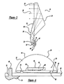
- Figure 1 is a broken-away perspective view of a vehicle including a headlight employing a plurality of headlight units each including a plurality of LED units emitting white light, according to an embodiment of the present invention
- Figure 2 is a perspective view of one of the headlight units separated from the vehicle headlight shown in figure 1 ;
- Figure 3 is a side view of the headlight unit shown in figure 2 showing the light rays;
- Figure 4 is front view of one of the LED units removed from the headlight unit shown in figure 2 ;
- Figure 5 is a cut-away side view of the LED unit shown in figure 4 ;
- Figure 6 is a top view of the LED unit shown in figure 4 ;
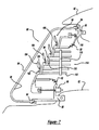
- Figure 7 is a cross-sectional view of a vehicle headlight employing a plurality of headlight units, according to another embodiment of the present invention.
- Figure 8 is a plan view of a lamp housing being coupled to a carrier by a flexible boot, according to an embodiment of the present invention.
- Figure 9 is a plan view of a lamp housing being coupled to a carrier by a flexible boot, according to another embodiment of the present invention.
- FIG. 1 is a broken-away perspective view of a vehicle 10 including a headlight 12.
- the headlight 12 includes five separate headlight units 14 each generating a separate beam of light.
- Each light beam generated by each headlight unit 14 forms the complete light beam from the headlight 12, where the light beams from the several headlight units 14 overlay each other to provide the desired light intensity.
- the headlight 12 is mounted to a vehicle structure 16 at a desirable location, and is positioned behind a non-active outer lens 18.
- the outer lens 18 can be eliminated by sealing the various environmentally sensitive components of the headlight 12 in other ways.
- each headlight unit 1 4 includes an LED design that emits white light that provides the intensity and directional requirements of the vehicle headlight regulations.
- the specific design, orientation, and number of headlight units 14 are not specific to the invention in that other configurations can be employed within the scope of the present invention.
- FIG 2 is a perspective view of one of the headlight units 14 removed from the headlight 12.
- the headlight unit 14 includes a reflective prism 24 made of a suitable optical material, such as a clear glass or plastic.
- a plurality of elongated primary lenses 28 are optically glued to a front face 30 of the prism 24.
- Each lens 28 is a single piece injection molded optical lens including a head portion 32 and an elongated body portion 34 defining a ridge 36 therebetween.
- the head portion 32 is molded over an LED unit 38, discussed in detail below, to form a single piece structure.
- the LED unit 38 is mounted in a die or tool in an injection molding machine.
- the mold has the same shape as the lens 28 so that when the optical plastic is injected into the mold, the resulting unit is a single piece combination of the light unit 38 and the lens 28.
- the LED unit 38 can include it's own clear protective dome that is glued to a cooperating cavity in the lens 28 by an optically neutral epoxy.
- the injection molded primary optic lens can be a dome lens formed over the LED unit 38. Additional optics can be then provided in connection with the primary optic lens, where air gaps may be provided between the various optics.
- the shape of the primary optic lens can be any shape suitable for a particular application.
- the primary optics i.e., the lens 28
- the lens 28 is the only optic that provides beam directing and focusing.
- the light is completely encapsulated in a solid dielectric, specifically the lens 28 and the prism 24, so that the light does not propagate through air prior to being emitted from the headlight unit 14. This provides desirable advantages because typically up to 5% of the light is lost if it propagates through air.
- the prism 24 can be eliminated, and the lens 28 can be directed in the desirable manner to provide the beam of light.
- the lens 28 can be tinted to provide the desired color of light.
- optics can be employed to create a far field beam pattern with a single lens.
- each LED unit 38 and associated lens 28 can each provide the complete or total beam pattern for the headlight 12. This has the advantage that if one or more of the LED units 38 burns out, part of the beam pattern will not be completely eliminated. Alternately, some of the LED units 38 can be provided for one part of the beam pattern, and others of the LED units 38 can be provided for other parts of the beam pattern.
- the LED units 38 are mounted to a common mounting plate 40. In this embodiment, there are six LED units 38 for each headlight unit 14 providing a total of thirty LED units 38.
- the light units 38 are spaced a certain distance apart on the mounting plate 40 to provide the desired intensity, the desired aesthetics and the ability to provide suitable cooling.
- a finned heat sink 42 is mounted to the mounting plate 40 for removing heat from the units 38.
- the heat sink 42 is intended to be a general representation of any heat sink or cooling mechanism, such as a thermoelectric cooler or heatpipe, suitable for the purposes described herein.
- the units 38 are coupled to the plate 40 by any suitable thermally conductive material.
- Figure 3 is a side view of the unit 14 depicting light rays 58 of the light generated by the LED units 38.
- light emitted from the LED unit 38 is directed to an outer surface 44 of the head portion 32 and is reflected therefrom into the body portion 34.
- the outer surface 44 is coated with a reflective film, such as a silver film.
- the silver film can be placed in the die when the lens 28 is molded so that it adheres to the surface 44. Part of the light is reflected from the surface 44 to be directed back towards the LED unit 38, as will be discussed in more detail below.
- Some of the light that is directed onto the body portion 34 is reflected off of an outer surface 46 of the body portion 34 and directed through the transition between the body portion 34 and the prism 24. The light is reflected and directed through the prism 24 to be emitted through the front face 30 of the prism 24 as a beam of white light.
- Figure 4 is a front view and figure 5 is a side view of one of the LED units 38.
- the unit 38 includes a metal core board (MCB) 48 that acts as a main substrate for the unit 38, and provides an electrical connection thereto.
- a series of solder or stud bumps 50 are deposited on a top surface 52 of the MCB 48, and are electrically coupled to suitable electrical traces thereon.
- the solder or stud bumps 50 are electrically coupled to electrical vias 54 extending through a submount 56 that is mounted to the top surface 52 of the MCB 48.
- the vias 54 are electrically coupled to solder or stud bumps 60 on a top surface 62 of the submount 56.
- the solder or stud bumps 60 are electrically coupled to an LED semiconductor chip 64 made of a semiconductor material that emits light in response to the electrical potential applied thereto.
- the semiconductor chip 64 emits blue light.
- a phosphor layer 66 is deposited over the chip 64. The phosphor layer 66 absorbs the blue light emitted by the chip 64 and emits the white light. Thus, when an electric potential is applied to the solder or stud bumps 50, the chip 64 is energized generating the light.
- the phosphor layer 66 can be eliminated and the lens 28, the prism 24 or other optic can be treated with a phosphor to convert the blue light to the white light.
- any known technique for generating white LED light can be employed that is suitable for a vehicle headlight.
- the various components of the light unit 38 discussed above can be made of any material suitable for the purposes discussed herein.
- the MCB 48 can be a suitable printed circuit board having copper traces
- the submount 56 can be made of AIN (aluminum nitrite) and the semiconductor chip 64 can be made of InGaN.
- AIN aluminum nitrite
- the semiconductor chip 64 can be made of InGaN.
- the submount 56 provides larger contact areas for the solder or stud bumps 50, which decreases adverse affects of the differences in coefficients of thermal expansion between the chip 64 and the MCB 48.
- the submount 56 may be eliminated if the coefficients of thermal expansion between the chip 64 and the MCB 48 can be suitably matched to maintain the desired connection over the entire range of operating temperatures.
- the stud bumps 60 are "scrubbed" or ultrasonically welded to electrical couple the chip 64 to traces on the submount 56.
- the chip 64 is mounted to the submount 56 by reflowing the solder bumps 60 to contact traces on the top surface 62 of the submount 56.
- the heat required to reflow the solder bump 60 may burn or otherwise damage the phosphor layer 66.
- the chip 64 is first mounted to the submount 56, or in an alternate embodiment directly to the MCB 48, before the phosphor layer 66 is deposited over the chip 64. Once the chip 64 is electrically coupled to the submount 56, a stencil is used to pattern the phosphor layer 66 so that it is deposited over the several chips 64. Thus, the phosphor layer 66 does not burn from the chip production heat.
- an underfill technique is used to help eliminate bridging of the submount 56, which results in more inherent adhesion of the submount 56 to the MCB 48.
- the binders and other elements of the solder paste matrix burn off after solder reflow.
- the metallization on the backside of the submount 56 can include 0.1-0.2 ⁇ m Ti, 0.2-0.3 ⁇ m Pt, 0.1 ⁇ m Au, 3.0-4.0 ⁇ m Ni or 0.1 ⁇ m Au. These metallizations do not need to match the solder paste, but the gold content of the solder paste must be such that brittle bonds do not form upon reflow.
- solder joint is made up of primarily a brittle structure, which becomes a possible failure point during vibration and/or thermal stresses. This also helps to hold the chip 64 during the injection molding process to eliminate breaking.
- the semiconductor chip 64 can have any shape that can be manufactured and provide the desired light pattern. Typically, semiconductor chips are formed by dicing a semiconductor die in a square pattern. Semiconductor chips being 1 mm by 1 mm square may be suitable for the LED units 38. However, in an alternate design the chip 64 can be cut from a semiconductor die in a rectangular pattern to provide an elongated chip that provides a more desirable light pattern. In one design, the chip 64 can be 1 mm by 6 mm or 1 mm by 2 mm. By providing a rectangular chip, variations in the collimation and spread of the light can be achieved that may be more desirable for a vehicle headlight. Also, a cluster of separate LED semiconductor chips of varying shapes can be provided on a common substrate to provide the desired light pattern.
- electrode path or patterns can be printed on the chip 64 to conduct the electricity to make the semiconductor operate.
- the electrode path is printed on the chip 64 in the form of the headlight cutoff (the area of light to dark imaged on the row).
- Another embodiment includes printing the cutoff pattern on the phosphor layer 66.
- the configuration of the unit 38 discussed above provides a chip-on-board electrical connection technology.
- the solder or stud bumps 50 and 60 provide direct mounting of the submount 56 to the MCB 48 and the chip 64 to the submount 56, as shown.
- using the chip-on-board technology provides other advantages, including a reduction of movement of the chip 64 during soldering that provides greater registration of the light to the optics, elimination of the thermal path by eliminating the heat slug heretofore employed in white LED designs, reduction of part count, and increased reliability because of the elimination of wire bonds to the chip 64.
- the lenses 28 need to be accurately aligned to their respective LED chip 64.
- a series of pins 68 associated with a die 70 are inserted in a registration hole 76 in the MCB 48 to provide alignment and registration.
- FIG. 6 is a top view of the light unit 38 depicting this part of the invention.
- the chip 64 is square.
- the top surface 62 of the submount 56 is metallized at first and second virtual image locations 72 and 74.
- the metallization can be any suitable reflective material, such as aluminum or silver. Light emitted from the chip 64 is directed to the outer surface 44 of the head portion 32, and some of the light is redirected back to the locations 72 and 74 as virtual images to be reflected therefrom.
- Some of the light from the semiconductor chip 64 is directed out of the lens 28 into the prism 24.
- the light that is reflected from the virtual image locations 72 and 74 is re-reflected off of the outer surface 44 of the head portion 32 to be directed into the body portion 34, out of the lens 28 and into the prism 24.
- the re-reflection of the light from the virtual image locations 72 and 74 generates higher intensity beam.
- the chip 64 is rectangular, the virtual images may be able to be eliminated.
- FIG. 7 is a cross-sectional view of a vehicle headlight 80, according to another embodiment of the present invention, mounted to a vehicle body panel 82.
- the headlight 80 includes an outer lens 84 that is mounted to a lamp housing 86 by a suitable glue or sealant at a joint 94 to define a sealed lamp compartment 98.
- the headlight 80 further includes a carrier 88 having the shape as shown to accommodate a plurality of headlight units 90, as will be discussed in more detail below.
- the carrier 88 is mounted to the lamp housing 86 by an adjuster 96 and a pivot element 110.
- the lamp housing 86 is rigidly mounted to the vehicle body panel 82.
- the adjuster 96 rotates the carrier 88 in two degrees of freedom on the pivot element 110 to align the headlight units 90.
- a flexible boot 92 is mounted to the lamp housing 86 and the carrier 88, as shown.
- the flexible boot 92 allows the carrier 88 to be rotated on the pivot element 110 while still maintaining the seal integrity of the lamp compartment 98.
- the flexible boot 92 can be made of any suitable material, such as rubber.
- the flexible boot 92 provides the ability for the headlight 80 to be directionally positioned without affecting the seal that prevents moisture from entering the lamp compartment 98.
- the carrier 88 is co-molded in combination with the flexible boot 92, and then the flexible boot 92 is clipped to the lamp housing 86 by some mechanical device (not shown) when it i s installed.
- the flexible boot 92 can be molded independent of the carrier 88 and the lamp housing 86, and clipped by a mechanical device at a later time during installation.
- the carrier 88 includes a heat sink 14, such as a plurality of spaced apart fins 112.
- the heat sink 114 is in thermal contact with air circulating through the engine compartment so that fins 112 are cooled, and thus heat is drawn away from the headlight units 90.
- the heat sink 114 can include a thermal pipe 118, a thermal cooler 116 or other suitable heat sinking device.
- Each of the headlight units 90 includes a lens 100 and an LED unit 102 of the type discussed above.
- a plurality of the lenses 100 and associated LED units 102 are mounted to a single prism 104 in the manner discussed above, where the light from all of the units 102 is emitted from a front face 106 of the prism 104.
- the units 90 are flipped 180° from those shown in figure 1 .
- the headlight units 102 are mounted to an indented portion 108 of the carrier 88, as shown.
- LED units employ drive modules that provide a constant current source to the LEDs for proper operation.
- the drive modules can provide a pulse width modulated signal.
- the drive module can be mounted to the headlight plate 88.
- the drive module can be integrated with the electronics of the LED or MCB to reduce weight and conserve space.
- Figures 8 and 9 are plan views showing techniques for sealing a vehicle headlight to a carrier discussed generally above, according to the invention, that allow the headlight lamp to be sealed and provide a rotational two-axis degree of freedom of the lamp optics needed for headlight aiming.
- FIG 8 is a plan view of a vehicle headlight assembly 120 that includes a lamp housing 122 that may include the LED units discussed above, or any other lamp housing and associated assembly known in the art.
- the assembly 120 further includes a carrier 126 including heat sink fins 128 for removing heat from the headlight lamp.
- the carrier 126 is a die cast carrier panel, and represents a suitable vehicle structure to which the lamp housing 122 is mounted.
- the carrier 126 is a plastic panel for an aluminum carrier assembly or any other suitable carrier panel for the purposes described herein.
- a rubber boot or bellows 132 provides flexible, coupling between the lamp housing 122 and the carrier 126.
- the bellows 132 includes a connecting structure 134 for connecting the bellows 132 to the lamp housing 122, and a connecting structure 136 for connecting the bellows 132 to the carrier 126.
- the carrier 126 and the lamp housing 122 are placed in a mold, and rubber material is injected into the mold to form the bellows 132 molded to the lamp housing 122 and the carrier 126, as shown.
- the lamp housing 122 can be positioned in the desired directional orientation by a suitable actuation device, and heat can still be removed therefrom through the bellows 132.
- FIG. 9 is a plan view of a headlight assembly 140, according to another embodiment of the present invention.
- the assembly 140 includes a lamp housing 142, a carrier 144 including an associated heat sink fins 146, and a rubber boot or bellows 148.
- the lamp housing 142 is placed in the bellows mold and the bellows 148 is molded thereto at a connection area 150.
- a mechanical clip 152 is placed in the mold, and is also co-molded to the bellows 148. The clip 152 is then clipped to an extended flange 154 of the carrier 144 to secure the lamp housing to the carrier 144 and the heat sink 146.
Landscapes
- Engineering & Computer Science (AREA)
- Physics & Mathematics (AREA)
- General Engineering & Computer Science (AREA)
- Optics & Photonics (AREA)
- General Physics & Mathematics (AREA)
- Microelectronics & Electronic Packaging (AREA)
- Mechanical Engineering (AREA)
- Geometry (AREA)
- Non-Portable Lighting Devices Or Systems Thereof (AREA)
- Led Device Packages (AREA)
- Arrangement Of Elements, Cooling, Sealing, Or The Like Of Lighting Devices (AREA)
Claims (28)
- Fahrzeugscheinwerfer (12), der eine Vielzahl von Leuchtdioden (LED)-Einheiten (38) verwendet, wobei dieser Fahrzeugscheinwerfer (12) weißes Licht abgibt,
dadurch gekennzeichnet, dass- dieser Fahrzeugscheinwerfer (12) separate Leuchteneinheiten (14) umfasst, die alle einen separaten Lichtstrahl erzeugen, die das vollständige Lichtstrahlmuster des Fahrzeugscheinwerfers (12) formen, wobei die Lichtstrahlen aus den mehreren Leuchteneinheiten (14) sich gegenseitig überlagern, um eine gewünschte Lichtstärke des Scheinwerfers (12) zu ergeben;- jede Leuchteneinheit (14) ein LED-Design aufweist, das eine Vielzahl von länglichen Primärlinsen (28) verwendet;- jede Primärlinse (28) eine spritzgegossene optische Linse aus einem Stück mit einem Kopfabschnitt (32) und einem länglichen Körperabschnitt (34) ist, die einen Grat (36) dazwischen definiert;- der Kopfabschnitt (32) über einer LED-Einheit (38) geformt ist, um eine einteilige Struktur der LED-Einheit (38) und der Primärlinse (28) zu formen;- Licht, das von einer LED-Einheit (38) abgegeben wird, an diesem Kopfabschnitt (32) in eine Primärlinse (28) eintritt, zu einer Außenfläche (44) des Kopfabschnitts (32) geleitet wird und von dort in den länglichen Körperabschnitt (34) reflektiert wird, um von diesem länglichen Körperabschnitt (34) aus die Primärlinse (28) zu verlassen. - Fahrzeugscheinwerfer nach Anspruch 1,
dadurch gekennzeichnet,
dass jeder Lichtstrahl, der von jeder LED-Einheit (38) und zugehörigen Linse (28) erzeugt wird, das komplette Lichtstrahlmuster für den Fahrzeugscheinwerfer (12) ergibt. - Fahrzeugscheinwerfer nach Anspruch 1,
dadurch gekennzeichnet,
dass einige der LED-Einheiten (38) und zugehörigen Linsen (28) einen Teil des Strahlmusters vom Fahrzeugscheinwerfer (12) erzeugen und andere der LED-Einheiten (38) und zugehörigen Linsen (28) andere Teile des Strahlmusters erzeugen. - Fahrzeugscheinwerfer nach Anspruch 1, 2 oder 3,
dadurch gekennzeichnet,
dass der Fahrzeugscheinwerfer (12) hinter einer nicht aktiven Außenlinse (18) angeordnet ist. - Fahrzeugscheinwerfer nach Anspruch 1, 2 oder 3,
dadurch gekennzeichnet,
dass die verschiedenen umweltempfindlichen Bauteile des Fahrzeugscheinwerfers (12) abgedichtet sind. - Fahrzeugscheinwerfer nach Anspruch 5,
dadurch gekennzeichnet,
dass eine Optik verwendet wird, um mit einer Einzellinse ein Fernfeldmuster zu erzeugen. - Fahrzeugscheinwerfer nach einem der vorherigen Ansprüche,
dadurch gekennzeichnet, dass- die Leuchteneinheit (14) ein reflektierendes Prisma (24) umfasst;- eine Vielzahl von länglichen Primärlinsen (28) optisch an eine Frontseite (30) des Prismas (24) geklebt sind;- das Licht völlig in ein Festdielektrikum eingekapselt ist, das durch die zu den LED-Einheiten (38) gehörigen Primärlinsen (28) und das Prisma (24) geformt wird, sodass das Licht sich nicht durch Luft ausbreitet, bevor es aus der Leuchteneinheit (14) ausgetreten ist. - Fahrzeugscheinwerfer nach einem der vorherigen Ansprüche,
dadurch gekennzeichnet,
dass die Außenfläche (44) mit einer reflektierenden Schicht beschichtet ist. - Fahrzeugscheinwerfer nach Anspruch 8,
dadurch gekennzeichnet,
dass die reflektierende Schicht an jeder Linse (28) geformt wird, wenn die Linse geformt wird. - Fahrzeugscheinwerfer nach einem der vorherigen Ansprüche,
dadurch gekennzeichnet,
dass die LED-Einheit (38) ihre eigene klare Schutzkuppel aufweist, die durch ein optisch neutrales Epoxid an einen zusammenwirkenden Hohlraum in der Primärlinse (28) geklebt ist. - Fahrzeugscheinwerfer nach einem der vorherigen Ansprüche,
dadurch gekennzeichnet,
dass eine Zusatzoptik in Verbindung mit den optischen Primärlinsen (28) vorgesehen ist. - Fahrzeugscheinwerfer nach einem der vorherigen Ansprüche,
dadurch gekennzeichnet,
dass Luftspalte zwischen benachbarten Primärlinsen (28) einer Leuchteneinheit (14) vorgesehen sind. - Fahrzeugscheinwerfer nach einem der vorherigen Ansprüche,
dadurch gekennzeichnet,
dass die LED-Einheiten (38) auf einer gemeinsamen Montageplatte (40) montiert sind. - Fahrzeugscheinwerfer nach Anspruch 13,
dadurch gekennzeichnet,
dass die LED-Einheiten (38) in einer bestimmten Entfernung auf der Montageplatte (40) beabstandet sind. - Fahrzeugscheinwerfer nach Anspruch 13 oder 14,
dadurch gekennzeichnet,
dass ein Rippenkühlkörper (42) auf der Montageplatte (40) montiert ist, um Wärme von den LED-Einheiten (38) abzuführen. - Fahrzeugscheinwerfer nach Anspruch 13 oder 14,
dadurch gekennzeichnet,
dass ein Kühlkörper (42) oder ein Kühlmechanismus wie ein thermoelektrischer Kühler oder ein Wärmerohr mit der Montageplatte (40) verbunden ist. - Fahrzeugscheinwerfer nach Anspruch 13, 14, 15 oder 16,
dadurch gekennzeichnet,
dass die LED-Einheiten (38) durch ein wärmeleitendes Material mit der Montageplatte (40) gekoppelt sind. - Fahrzeugscheinwerfer nach einem der vorherigen Ansprüche,
dadurch gekennzeichnet,
dass auf der LED-Einheit (38) vor dem Spritzguss eine Silikongelschicht geformt wird. - Fahrzeugscheinwerfer nach einem der vorherigen Ansprüche,
dadurch gekennzeichnet,
dass mehrere der Primärlinsen (28) und zugehörigen LED-Einheiten (38) optisch an eine einzige optische Struktur (24) geklebt sind, die das ganze Licht aus allen LED-Einheiten (38) sammelt. - Fahrzeugscheinwerfer nach einem der vorherigen Ansprüche,
dadurch gekennzeichnet,
dass die LED-Einheiten (38) die Chip-on-Board-Technologie verwenden, wo ein LED-Halbleiterchip (64) durch Löt- oder Stud-Bumps direkt auf ein Montagebasis (56)-Substrat montiert ist. - Fahrzeugscheinwerfer nach Anspruch 20,
dadurch gekennzeichnet, dass- jede LED-Einheit (38) eine Metallkern-Leiterplatte (MCB) (48) aufweist, die als ein Hauptsubstrat für die LED-Einheit (38) dient und eine elektrische Verbindung damit herstellt;- eine Reihe von Löt- oder Stud-Bumps (50) auf einer Oberseite (52) der MCB (48) angeordnet sind und mit geeigneten Leiterbahnen darauf elektrisch verbunden sind;- die Löt- oder Stud-Bumps (50) mit elektrischen Durchgangsleitungen elektrisch verbunden sind, die durch eine Montagebasis (56) verlaufen, das auf der Oberseite (52) der MCB (48) montiert ist;- diese Durchgangsleitungen (54) mit Löt- oder Stud-Bumps (60) auf einer Oberseite (62) der Montagebasis (56) elektrisch verbunden sind;- diese Löt- oder Stud-Bumps (60) mit einem LED-Halbleiterchip (64) elektrisch verbunden sind. - Fahrzeugscheinwerfer nach Anspruch 21,
dadurch gekennzeichnet,
dass die MCB (48) eine Leiterplatte mit Kupferbahnen ist. - Fahrzeugscheinwerfer nach Anspruch 21 oder 22,
dadurch gekennzeichnet,
dass die Montagebasis (56) aus Aluminiumnitrit (AlN) besteht. - Fahrzeugscheinwerfer nach Anspruch 21, 22 oder 23,
dadurch gekennzeichnet,
dass der LED-Halbleiterchip (64) aus InGaN besteht. - Fahrzeugscheinwerfer nach einem der Ansprüche 1 bis 19,
dadurch gekennzeichnet,
dass die LED-Einheiten (38) LED-Halbleiterchips (64) verwenden, die direkt auf ein Primärsubstrat montiert sind. - Fahrzeugscheinwerfer nach einem der Ansprüche 20 bis 25,
dadurch gekennzeichnet,
dass die optische Primärlinse (28) einer LED-Einheit (38) in Kontakt mit einem Grundsubstrat auf der LED-Einheit (38) spritzgegossen ist. - Fahrzeugscheinwerfer nach einem der Ansprüche 20 bis 26,
dadurch gekennzeichnet,
dass der LED-Halbleiterchip (64) blaues Licht abgibt, wobei auf dem Chip (64) eine Phosphorschicht (66) aufgetragen ist. - Fahrzeugscheinwerfer nach einem der Ansprüche 20 bis 26,
dadurch gekennzeichnet,
dass der LED-Halbleiterchip (64) blaues Licht abgibt, wobei die Primärlinse (28) oder das Prisma (24) oder eine andere Optik mit einem Phosphor behandelt sind, um blaues Licht in weißes Licht umzuwandeln.
Applications Claiming Priority (3)
| Application Number | Priority Date | Filing Date | Title |
|---|---|---|---|
| US39634802P | 2002-07-16 | 2002-07-16 | |
| US396348P | 2002-07-16 | ||
| PCT/US2003/022247 WO2004007241A2 (en) | 2002-07-16 | 2003-07-16 | White led headlight |
Publications (3)
| Publication Number | Publication Date |
|---|---|
| EP1535299A2 EP1535299A2 (de) | 2005-06-01 |
| EP1535299A4 EP1535299A4 (de) | 2007-08-08 |
| EP1535299B1 true EP1535299B1 (de) | 2009-11-18 |
Family
ID=30116014
Family Applications (1)
| Application Number | Title | Priority Date | Filing Date |
|---|---|---|---|
| EP03764747A Expired - Lifetime EP1535299B1 (de) | 2002-07-16 | 2003-07-16 | Weiss-led-scheinwerfer |
Country Status (6)
| Country | Link |
|---|---|
| US (1) | US7777405B2 (de) |
| EP (1) | EP1535299B1 (de) |
| KR (1) | KR20050044894A (de) |
| AU (1) | AU2003261170A1 (de) |
| DE (1) | DE60330153D1 (de) |
| WO (1) | WO2004007241A2 (de) |
Cited By (1)
| Publication number | Priority date | Publication date | Assignee | Title |
|---|---|---|---|---|
| WO2015143398A1 (en) * | 2014-03-21 | 2015-09-24 | Kc Hilites, Inc. | Lighting system using an electrically conductive power strip |
Families Citing this family (74)
| Publication number | Priority date | Publication date | Assignee | Title |
|---|---|---|---|---|
| US6896381B2 (en) | 2002-10-11 | 2005-05-24 | Light Prescriptions Innovators, Llc | Compact folded-optics illumination lens |
| US7042655B2 (en) | 2002-12-02 | 2006-05-09 | Light Prescriptions Innovators, Llc | Apparatus and method for use in fulfilling illumination prescription |
| US6924943B2 (en) | 2002-12-02 | 2005-08-02 | Light Prescriptions Innovators, Llc | Asymmetric TIR lenses producing off-axis beams |
| US7377671B2 (en) | 2003-02-04 | 2008-05-27 | Light Prescriptions Innovators, Llc | Etendue-squeezing illumination optics |
| JP4047185B2 (ja) | 2003-02-06 | 2008-02-13 | 株式会社小糸製作所 | 車両用前照灯及び発光モジュール |
| JP4102240B2 (ja) * | 2003-04-08 | 2008-06-18 | 株式会社小糸製作所 | 車両用前照灯 |
| US7021797B2 (en) | 2003-05-13 | 2006-04-04 | Light Prescriptions Innovators, Llc | Optical device for repositioning and redistributing an LED's light |
| US7329029B2 (en) | 2003-05-13 | 2008-02-12 | Light Prescriptions Innovators, Llc | Optical device for LED-based lamp |
| US8075147B2 (en) | 2003-05-13 | 2011-12-13 | Light Prescriptions Innovators, Llc | Optical device for LED-based lamp |
| EP1664851B1 (de) | 2003-07-28 | 2014-11-12 | Light Prescriptions Innovators, LLC. | Dreidimensionales gleichzeitiges mehrfachoberflächen-verfahren und daraus entwickelte freiform-beleuchtungsoptik |
| EP1660918B1 (de) | 2003-07-29 | 2017-03-15 | Light Engine Limited | Umfänglich emittierende leuchtvorrichtungen und durch transversalachsen-profil-sweeps gebildete linsenelemente |
| EP1663705B1 (de) * | 2003-09-08 | 2011-08-24 | odelo GmbH | Vorrichtung und verfahren zur montage und einstellung von led-scheinwerfern |
| JP4231418B2 (ja) * | 2004-01-07 | 2009-02-25 | 株式会社小糸製作所 | 発光モジュール及び車両用灯具 |
| US7414546B2 (en) | 2004-07-08 | 2008-08-19 | Honeywell International Inc. | White anti-collision light utilizing light-emitting diode (LED) technology |
| DE102004047324A1 (de) | 2004-09-29 | 2006-04-13 | Osram Opto Semiconductors Gmbh | Leuchtdiodenanordnung |
| ATE458166T1 (de) * | 2004-10-18 | 2010-03-15 | Koninkl Philips Electronics Nv | Hocheffiziente led-lichtquellenanordnung |
| US20060097385A1 (en) * | 2004-10-25 | 2006-05-11 | Negley Gerald H | Solid metal block semiconductor light emitting device mounting substrates and packages including cavities and heat sinks, and methods of packaging same |
| KR100867515B1 (ko) * | 2004-12-06 | 2008-11-07 | 삼성전기주식회사 | 발광소자 패키지 |
| KR100624449B1 (ko) * | 2004-12-08 | 2006-09-18 | 삼성전기주식회사 | 요철 구조를 포함하는 발광 소자 및 그 제조 방법 |
| US20070145386A1 (en) * | 2004-12-08 | 2007-06-28 | Samsung Electro-Mechanics Co., Ltd. | Semiconductor light emitting device and method of manufacturing the same |
| WO2006072176A1 (en) | 2005-01-05 | 2006-07-13 | Tir Systems Ltd. | Thermally and electrically conductive apparatus |
| US8419232B2 (en) | 2005-07-28 | 2013-04-16 | Light Prescriptions Innovators, Llc | Free-form lenticular optical elements and their application to condensers and headlamps |
| US8393777B2 (en) | 2005-07-28 | 2013-03-12 | Light Prescriptions Innovators, Llc | Etendue-conserving illumination-optics for backlights and frontlights |
| DE102005054508A1 (de) * | 2005-11-16 | 2007-05-31 | Hella Kgaa Hueck & Co. | Scheinwerfer oder Leuchte für Fahrzeuge |
| US7560742B2 (en) * | 2005-11-28 | 2009-07-14 | Magna International Inc. | Semiconductor-based lighting systems and lighting system components for automotive use |
| DE202006000878U1 (de) * | 2006-01-20 | 2006-04-13 | Hella Kgaa Hueck & Co. | Scheinwerfersystem |
| US8434912B2 (en) | 2006-02-27 | 2013-05-07 | Illumination Management Solutions, Inc. | LED device for wide beam generation |
| CA2641832C (en) | 2006-02-27 | 2012-10-23 | Illumination Management Solutions Inc. | An improved led device for wide beam generation |
| KR100754886B1 (ko) * | 2006-03-31 | 2007-09-04 | 서울반도체 주식회사 | 차량용 발광 다이오드 전조등 |
| CA2645228A1 (en) | 2006-05-02 | 2007-11-15 | Superbulbs, Inc. | Method of light dispersion and preferential scattering of certain wavelengths of light for light-emitting diodes and bulbs constructed therefrom |
| EP2022077A4 (de) * | 2006-05-02 | 2011-10-26 | Superbulbs Inc | Kunststoff-led-birne |
| BRPI0710966A2 (pt) * | 2006-05-02 | 2012-02-28 | Superbulbs, Inc | projeto de remoção de calor para bulbos de led |
| JP2009538532A (ja) | 2006-05-23 | 2009-11-05 | クリー エル イー ディー ライティング ソリューションズ インコーポレイテッド | 照明装置 |
| JP2009540595A (ja) | 2006-06-14 | 2009-11-19 | コーニンクレッカ フィリップス エレクトロニクス エヌ ヴィ | 照明デバイス |
| KR100770642B1 (ko) * | 2006-06-28 | 2007-10-29 | 서울반도체 주식회사 | 자동차 헤드라이트용 발광 다이오드 모듈과 이를 이용한조절식 전방조명시스템 |
| WO2008022065A2 (en) | 2006-08-11 | 2008-02-21 | Light Prescriptions Innovators, Llc | Led luminance-enhancement and color-mixing by rotationally multiplexed beam-combining |
| DE102006041959A1 (de) * | 2006-08-30 | 2008-03-06 | Karl Storz Gmbh & Co. Kg | Beleuchtungssystem zum Erzeugen von Licht und zum Einkoppeln des Lichts in ein proximales Ende eines Lichtleitkabels einer Beobachtungsvorrichtung für die Endoskopie oder Mikroskopie |
| KR100765995B1 (ko) | 2006-09-15 | 2007-10-12 | 에스엘 주식회사 | 발광다이오드 광원 헤드 램프 |
| CN101687473B (zh) | 2007-05-21 | 2014-12-03 | 照明管理解决方案有限公司 | 改进的用于生成宽束的led装置以及制造该装置的方法 |
| DE102007042625A1 (de) * | 2007-09-08 | 2009-03-12 | GM Global Technology Operations, Inc., Detroit | Leuchtenanordnung |
| US8439528B2 (en) | 2007-10-03 | 2013-05-14 | Switch Bulb Company, Inc. | Glass LED light bulbs |
| KR20100110770A (ko) * | 2007-10-24 | 2010-10-13 | 슈퍼불브스, 인크. | Led 광원용 확산기 |
| DE102007053611B3 (de) * | 2007-11-08 | 2009-07-09 | Zett Optics Gmbh | Leuchte |
| DE102008025397A1 (de) | 2008-05-28 | 2009-12-24 | Osram Gesellschaft mit beschränkter Haftung | Fahrzeugbeleuchtungsvorrichtung mit mindestens zwei Halbleiter-Leuchtelementen |
| WO2010019810A1 (en) | 2008-08-14 | 2010-02-18 | Cooper Technologies Company | Led devices for offset wide beam generation |
| JP5830380B2 (ja) | 2008-09-05 | 2015-12-09 | コーニンクレッカ フィリップス エヌ ヴェKoninklijke Philips N.V. | ランプアセンブリ |
| US20160053977A1 (en) | 2008-09-24 | 2016-02-25 | B/E Aerospace, Inc. | Flexible led lighting element |
| TW201034256A (en) * | 2008-12-11 | 2010-09-16 | Illumitex Inc | Systems and methods for packaging light-emitting diode devices |
| FR2941033A1 (fr) * | 2009-01-15 | 2010-07-16 | Peugeot Citroen Automobiles Sa | Bloc optique a amplification de photons par luminescence |
| AT508604B1 (de) * | 2009-07-31 | 2012-07-15 | Zizala Lichtsysteme Gmbh | Led-kraftfahrzeugscheinwerfer zur erzeugung einer dynamischen lichtverteilung |
| KR101087742B1 (ko) * | 2009-09-25 | 2011-11-30 | 에스엘 주식회사 | 차량용 램프 장치 |
| WO2011050267A2 (en) * | 2009-10-22 | 2011-04-28 | Waqidi Falicoff | Solid-state light bulb |
| AU2009101168B4 (en) * | 2009-11-16 | 2011-12-22 | Jurgens, Elise Rachel | LED light mount |
| WO2011066421A2 (en) | 2009-11-25 | 2011-06-03 | Cooper Technologies Company | Systems, methods, and devices for sealing led light sources in a light module |
| CN101915404B (zh) * | 2010-07-30 | 2014-07-16 | 深圳市中庆微科技开发有限公司 | 一种超散热led模块 |
| US8388198B2 (en) | 2010-09-01 | 2013-03-05 | Illumination Management Solutions, Inc. | Device and apparatus for efficient collection and re-direction of emitted radiation |
| DE102010048596A1 (de) * | 2010-10-15 | 2012-04-19 | Hella Kgaa Hueck & Co. | Scheinwerfer für ein Fahrzeug mit einem LED-Hauptlichtmodul |
| US9518711B2 (en) | 2011-09-27 | 2016-12-13 | Truck-Lite Co., Llc | Modular headlamp assembly |
| US9140430B2 (en) | 2011-02-28 | 2015-09-22 | Cooper Technologies Company | Method and system for managing light from a light emitting diode |
| EP2681484B1 (de) | 2011-02-28 | 2023-11-08 | Signify Holding B.V. | Verfahren und system zur verwaltung der lichtemission einer lichtemittierenden diode |
| US8591069B2 (en) | 2011-09-21 | 2013-11-26 | Switch Bulb Company, Inc. | LED light bulb with controlled color distribution using quantum dots |
| DE112012000572A5 (de) * | 2011-11-11 | 2013-11-21 | Docter Optics Se | Scheinwerferlinse für einen Fahrzeugscheinwerfer |
| AT512246B1 (de) * | 2011-11-22 | 2014-02-15 | Zizala Lichtsysteme Gmbh | Led-projektionsmodul und scheinwerfer mit modul |
| DE102012009596A1 (de) | 2012-05-15 | 2013-11-21 | Docter Optics Se | Verfahren zum Herstellen einer Scheinwerferlinse |
| DE102013006707B4 (de) | 2012-05-26 | 2025-11-27 | Docter Optics Se | Scheinwerferlinse für einen Fahrzeugscheinwerfer |
| US9080739B1 (en) | 2012-09-14 | 2015-07-14 | Cooper Technologies Company | System for producing a slender illumination pattern from a light emitting diode |
| EP2711900A1 (de) | 2012-09-20 | 2014-03-26 | Synegration AG | Elektronisches System und Verfahren zur Durchführung einer Abstimmung |
| CN104919243A (zh) * | 2012-11-14 | 2015-09-16 | 库珀技术公司 | 用于管理来自发光二极管的光的方法和系统 |
| US9200765B1 (en) | 2012-11-20 | 2015-12-01 | Cooper Technologies Company | Method and system for redirecting light emitted from a light emitting diode |
| US10506339B2 (en) | 2014-09-29 | 2019-12-10 | B/E Aerospace, Inc. | Smart passenger service unit |
| EP3201089B1 (de) | 2014-09-29 | 2021-04-07 | B/E Aerospace, Inc. | Intelligente fahrgastserviceeinheit |
| WO2016064733A2 (en) * | 2014-10-20 | 2016-04-28 | Ipg Photonics Corporation | Vehicular lighting system |
| EP3289283B1 (de) * | 2015-04-27 | 2022-11-02 | B/E Aerospace, Inc. | Flexibles led-beleuchtungselement |
| JP7579723B2 (ja) * | 2021-03-10 | 2024-11-08 | スタンレー電気株式会社 | 車両用灯具 |
Family Cites Families (17)
| Publication number | Priority date | Publication date | Assignee | Title |
|---|---|---|---|---|
| US4774434A (en) * | 1986-08-13 | 1988-09-27 | Innovative Products, Inc. | Lighted display including led's mounted on a flexible circuit board |
| JPH0446322Y2 (de) * | 1988-08-02 | 1992-10-30 | ||
| US5471371A (en) * | 1993-01-08 | 1995-11-28 | Ford Motor Company | High efficiency illuminator |
| US5709453A (en) * | 1994-08-16 | 1998-01-20 | Krent; Edward D. | Vehicle lighting having remote light source |
| JPH09204803A (ja) * | 1996-01-29 | 1997-08-05 | Koito Mfg Co Ltd | 前照灯のエイミング装置 |
| TW383508B (en) | 1996-07-29 | 2000-03-01 | Nichia Kagaku Kogyo Kk | Light emitting device and display |
| US5857767A (en) | 1996-09-23 | 1999-01-12 | Relume Corporation | Thermal management system for L.E.D. arrays |
| KR100198460B1 (ko) * | 1996-10-29 | 1999-06-15 | 이계철 | 브이홈에 정렬된 렌즈를 가진 광모듈 및 그 제작방법 |
| US5813753A (en) * | 1997-05-27 | 1998-09-29 | Philips Electronics North America Corporation | UV/blue led-phosphor device with efficient conversion of UV/blues light to visible light |
| FR2800335B1 (fr) * | 1999-10-28 | 2001-12-21 | Valeo Vision | Projecteur de vehicule automobile a moyens de reglage d'orientation de reflecteur et moyens pour un changement de lampe facilite |
| TW465123B (en) * | 2000-02-02 | 2001-11-21 | Ind Tech Res Inst | High power white light LED |
| DE10009782B4 (de) * | 2000-03-01 | 2010-08-12 | Automotive Lighting Reutlingen Gmbh | Beleuchtungseinrichtung eines Fahrzeugs |
| US6517218B2 (en) * | 2000-03-31 | 2003-02-11 | Relume Corporation | LED integrated heat sink |
| IT1320547B1 (it) * | 2000-07-21 | 2003-12-10 | Fiat Ricerche | Dispositivo di illuminazione, particolarmente proiettore o fanale diautoveicolo con distribuzione a matrice di sorgenti luminose |
| US6345903B1 (en) * | 2000-09-01 | 2002-02-12 | Citizen Electronics Co., Ltd. | Surface-mount type emitting diode and method of manufacturing same |
| US6650044B1 (en) * | 2000-10-13 | 2003-11-18 | Lumileds Lighting U.S., Llc | Stenciling phosphor layers on light emitting diodes |
| EP1663705B1 (de) * | 2003-09-08 | 2011-08-24 | odelo GmbH | Vorrichtung und verfahren zur montage und einstellung von led-scheinwerfern |
-
2003
- 2003-07-16 EP EP03764747A patent/EP1535299B1/de not_active Expired - Lifetime
- 2003-07-16 US US10/521,286 patent/US7777405B2/en not_active Expired - Fee Related
- 2003-07-16 AU AU2003261170A patent/AU2003261170A1/en not_active Abandoned
- 2003-07-16 WO PCT/US2003/022247 patent/WO2004007241A2/en not_active Ceased
- 2003-07-16 DE DE60330153T patent/DE60330153D1/de not_active Expired - Lifetime
- 2003-07-16 KR KR1020057000879A patent/KR20050044894A/ko not_active Withdrawn
Cited By (2)
| Publication number | Priority date | Publication date | Assignee | Title |
|---|---|---|---|---|
| WO2015143398A1 (en) * | 2014-03-21 | 2015-09-24 | Kc Hilites, Inc. | Lighting system using an electrically conductive power strip |
| CN106255617A (zh) * | 2014-03-21 | 2016-12-21 | 卡西海利特有限公司 | 使用导电电力板的照明系统 |
Also Published As
| Publication number | Publication date |
|---|---|
| EP1535299A2 (de) | 2005-06-01 |
| AU2003261170A1 (en) | 2004-02-02 |
| DE60330153D1 (de) | 2009-12-31 |
| KR20050044894A (ko) | 2005-05-13 |
| US7777405B2 (en) | 2010-08-17 |
| EP1535299A4 (de) | 2007-08-08 |
| US20070018181A1 (en) | 2007-01-25 |
| WO2004007241A3 (en) | 2005-02-24 |
| WO2004007241A2 (en) | 2004-01-22 |
| AU2003261170A8 (en) | 2004-02-02 |
Similar Documents
| Publication | Publication Date | Title |
|---|---|---|
| EP1535299B1 (de) | Weiss-led-scheinwerfer | |
| EP1393374B1 (de) | Hochleistungs led-lampe für spot-beleuchtung | |
| US7932523B2 (en) | LED lamp for light source of lighting device | |
| US7059754B2 (en) | Apparatus and method for providing a modular vehicle light device | |
| US7607801B2 (en) | Light emitting apparatus | |
| US8847242B2 (en) | Multi-element LED lamp | |
| US7563005B2 (en) | Light source module and lamp equipped with the same | |
| CN101463960B (zh) | 车灯及其制造方法 | |
| US20080278954A1 (en) | Mounting Assembly for Optoelectronic Devices | |
| KR101837758B1 (ko) | 차량용 등기구의 반도체형 광원의 광원 유닛, 차량용 등기구 | |
| JP2005050811A (ja) | Led光源組立品 | |
| JP2005537665A (ja) | Led平面型光源及びこれを備えた薄型ヘッドライト | |
| JP2007073968A (ja) | フレキシブル回路支持体を利用する薄型の光源 | |
| JP2003158302A (ja) | 発光ダイオード | |
| JP6967917B2 (ja) | 灯具ユニット及び車両用灯具 | |
| JP2006310204A (ja) | Led灯具 | |
| CN106481994B (zh) | 具有发光二极管的发光机构 | |
| CN109237319A (zh) | 将led裸片与引线框架带的接合 | |
| US20080273332A1 (en) | Light Device | |
| CN112393198A (zh) | 微型化光线投射装置 | |
| KR102872982B1 (ko) | 광원 모듈 및 이를 구비한 차량용 램프 | |
| JP2007318176A (ja) | 発光ダイオード | |
| JP2022082076A (ja) | 車両用灯具用光源ユニット及び車両用灯具 | |
| JP7673418B2 (ja) | 車両用灯具 | |
| CN101120203A (zh) | 照明设备 |
Legal Events
| Date | Code | Title | Description |
|---|---|---|---|
| PUAI | Public reference made under article 153(3) epc to a published international application that has entered the european phase |
Free format text: ORIGINAL CODE: 0009012 |
|
| 17P | Request for examination filed |
Effective date: 20050120 |
|
| AK | Designated contracting states |
Kind code of ref document: A2 Designated state(s): AT BE BG CH CY CZ DE DK EE ES FI FR GB GR HU IE IT LI LU MC NL PT RO SE SI SK TR |
|
| AX | Request for extension of the european patent |
Extension state: AL LT LV MK |
|
| DAX | Request for extension of the european patent (deleted) | ||
| RBV | Designated contracting states (corrected) |
Designated state(s): DE FR GB |
|
| RIN1 | Information on inventor provided before grant (corrected) |
Inventor name: LUCAS, KYLE, P. Inventor name: STEEN, RONALD, L. |
|
| RIC1 | Information provided on ipc code assigned before grant |
Ipc: B60Q 1/04 20060101AFI20070524BHEP Ipc: F21W 101/10 20060101ALN20070524BHEP Ipc: F21S 8/10 20060101ALI20070524BHEP Ipc: F21Y 101/02 20060101ALN20070524BHEP |
|
| A4 | Supplementary search report drawn up and despatched |
Effective date: 20070710 |
|
| 17Q | First examination report despatched |
Effective date: 20071012 |
|
| RAP1 | Party data changed (applicant data changed or rights of an application transferred) |
Owner name: SCHEFENACKER VISION SYSTEMS GERMANY GMBH |
|
| RAP1 | Party data changed (applicant data changed or rights of an application transferred) |
Owner name: ODELO GMBH |
|
| GRAP | Despatch of communication of intention to grant a patent |
Free format text: ORIGINAL CODE: EPIDOSNIGR1 |
|
| GRAS | Grant fee paid |
Free format text: ORIGINAL CODE: EPIDOSNIGR3 |
|
| GRAA | (expected) grant |
Free format text: ORIGINAL CODE: 0009210 |
|
| AK | Designated contracting states |
Kind code of ref document: B1 Designated state(s): DE FR GB |
|
| REG | Reference to a national code |
Ref country code: GB Ref legal event code: FG4D |
|
| REF | Corresponds to: |
Ref document number: 60330153 Country of ref document: DE Date of ref document: 20091231 Kind code of ref document: P |
|
| PLBE | No opposition filed within time limit |
Free format text: ORIGINAL CODE: 0009261 |
|
| STAA | Information on the status of an ep patent application or granted ep patent |
Free format text: STATUS: NO OPPOSITION FILED WITHIN TIME LIMIT |
|
| 26N | No opposition filed |
Effective date: 20100819 |
|
| GBPC | Gb: european patent ceased through non-payment of renewal fee |
Effective date: 20100716 |
|
| PG25 | Lapsed in a contracting state [announced via postgrant information from national office to epo] |
Ref country code: GB Free format text: LAPSE BECAUSE OF NON-PAYMENT OF DUE FEES Effective date: 20100716 |
|
| REG | Reference to a national code |
Ref country code: DE Ref legal event code: R082 Ref document number: 60330153 Country of ref document: DE Representative=s name: PATENTANWALTSKANZLEI MEYER, DE |
|
| REG | Reference to a national code |
Ref country code: DE Ref legal event code: R081 Ref document number: 60330153 Country of ref document: DE Owner name: ODELO GMBH, DE Free format text: FORMER OWNER: ODELO GMBH, 71409 SCHWAIKHEIM, DE Effective date: 20150423 Ref country code: DE Ref legal event code: R082 Ref document number: 60330153 Country of ref document: DE Representative=s name: PATENTANWALTSKANZLEI MEYER, DE Effective date: 20150423 |
|
| REG | Reference to a national code |
Ref country code: FR Ref legal event code: CA Effective date: 20150710 |
|
| REG | Reference to a national code |
Ref country code: FR Ref legal event code: PLFP Year of fee payment: 14 |
|
| REG | Reference to a national code |
Ref country code: FR Ref legal event code: PLFP Year of fee payment: 15 |
|
| REG | Reference to a national code |
Ref country code: FR Ref legal event code: PLFP Year of fee payment: 16 |
|
| PGFP | Annual fee paid to national office [announced via postgrant information from national office to epo] |
Ref country code: FR Payment date: 20190719 Year of fee payment: 17 Ref country code: DE Payment date: 20190719 Year of fee payment: 17 |
|
| REG | Reference to a national code |
Ref country code: DE Ref legal event code: R119 Ref document number: 60330153 Country of ref document: DE |
|
| PG25 | Lapsed in a contracting state [announced via postgrant information from national office to epo] |
Ref country code: FR Free format text: LAPSE BECAUSE OF NON-PAYMENT OF DUE FEES Effective date: 20200731 |
|
| PG25 | Lapsed in a contracting state [announced via postgrant information from national office to epo] |
Ref country code: DE Free format text: LAPSE BECAUSE OF NON-PAYMENT OF DUE FEES Effective date: 20210202 |