EP1534946B1 - Verfahren zum abschliessen eines drosselklappenstutzens - Google Patents
Verfahren zum abschliessen eines drosselklappenstutzens Download PDFInfo
- Publication number
- EP1534946B1 EP1534946B1 EP03750284A EP03750284A EP1534946B1 EP 1534946 B1 EP1534946 B1 EP 1534946B1 EP 03750284 A EP03750284 A EP 03750284A EP 03750284 A EP03750284 A EP 03750284A EP 1534946 B1 EP1534946 B1 EP 1534946B1
- Authority
- EP
- European Patent Office
- Prior art keywords
- throttle valve
- throttle
- compensation element
- elastic compensation
- wall
- Prior art date
- Legal status (The legal status is an assumption and is not a legal conclusion. Google has not performed a legal analysis and makes no representation as to the accuracy of the status listed.)
- Expired - Lifetime
Links
- 238000000034 method Methods 0.000 title claims description 18
- 238000007789 sealing Methods 0.000 title 1
- 229920003023 plastic Polymers 0.000 claims description 8
- 239000004033 plastic Substances 0.000 claims description 8
- 239000000853 adhesive Substances 0.000 claims description 7
- 230000001070 adhesive effect Effects 0.000 claims description 7
- 239000006260 foam Substances 0.000 claims description 7
- 238000003825 pressing Methods 0.000 claims description 7
- 229910052782 aluminium Inorganic materials 0.000 claims description 4
- XAGFODPZIPBFFR-UHFFFAOYSA-N aluminium Chemical compound [Al] XAGFODPZIPBFFR-UHFFFAOYSA-N 0.000 claims description 4
- 229920002292 Nylon 6 Polymers 0.000 claims description 3
- 229910052751 metal Inorganic materials 0.000 claims description 3
- 239000002184 metal Substances 0.000 claims description 3
- 238000004026 adhesive bonding Methods 0.000 claims description 2
- 239000004411 aluminium Substances 0.000 claims 2
- 230000000295 complement effect Effects 0.000 description 3
- 239000007789 gas Substances 0.000 description 2
- 239000003292 glue Substances 0.000 description 2
- 238000009423 ventilation Methods 0.000 description 2
- CERQOIWHTDAKMF-UHFFFAOYSA-M Methacrylate Chemical compound CC(=C)C([O-])=O CERQOIWHTDAKMF-UHFFFAOYSA-M 0.000 description 1
- 230000015572 biosynthetic process Effects 0.000 description 1
- 230000015556 catabolic process Effects 0.000 description 1
- 150000001875 compounds Chemical class 0.000 description 1
- 238000004519 manufacturing process Methods 0.000 description 1
- 239000000463 material Substances 0.000 description 1
- 229920000642 polymer Polymers 0.000 description 1
- 238000012805 post-processing Methods 0.000 description 1
- 238000003466 welding Methods 0.000 description 1
Images

Classifications
-
- F—MECHANICAL ENGINEERING; LIGHTING; HEATING; WEAPONS; BLASTING
- F02—COMBUSTION ENGINES; HOT-GAS OR COMBUSTION-PRODUCT ENGINE PLANTS
- F02D—CONTROLLING COMBUSTION ENGINES
- F02D9/00—Controlling engines by throttling air or fuel-and-air induction conduits or exhaust conduits
- F02D9/08—Throttle valves specially adapted therefor; Arrangements of such valves in conduits
- F02D9/10—Throttle valves specially adapted therefor; Arrangements of such valves in conduits having pivotally-mounted flaps
-
- F—MECHANICAL ENGINEERING; LIGHTING; HEATING; WEAPONS; BLASTING
- F16—ENGINEERING ELEMENTS AND UNITS; GENERAL MEASURES FOR PRODUCING AND MAINTAINING EFFECTIVE FUNCTIONING OF MACHINES OR INSTALLATIONS; THERMAL INSULATION IN GENERAL
- F16K—VALVES; TAPS; COCKS; ACTUATING-FLOATS; DEVICES FOR VENTING OR AERATING
- F16K1/00—Lift valves or globe valves, i.e. cut-off apparatus with closure members having at least a component of their opening and closing motion perpendicular to the closing faces
- F16K1/16—Lift valves or globe valves, i.e. cut-off apparatus with closure members having at least a component of their opening and closing motion perpendicular to the closing faces with pivoted closure-members
- F16K1/18—Lift valves or globe valves, i.e. cut-off apparatus with closure members having at least a component of their opening and closing motion perpendicular to the closing faces with pivoted closure-members with pivoted discs or flaps
- F16K1/22—Lift valves or globe valves, i.e. cut-off apparatus with closure members having at least a component of their opening and closing motion perpendicular to the closing faces with pivoted closure-members with pivoted discs or flaps with axis of rotation crossing the valve member, e.g. butterfly valves
- F16K1/226—Shaping or arrangements of the sealing
- F16K1/2261—Shaping or arrangements of the sealing the sealing being arranged on the valve member
-
- F—MECHANICAL ENGINEERING; LIGHTING; HEATING; WEAPONS; BLASTING
- F16—ENGINEERING ELEMENTS AND UNITS; GENERAL MEASURES FOR PRODUCING AND MAINTAINING EFFECTIVE FUNCTIONING OF MACHINES OR INSTALLATIONS; THERMAL INSULATION IN GENERAL
- F16K—VALVES; TAPS; COCKS; ACTUATING-FLOATS; DEVICES FOR VENTING OR AERATING
- F16K1/00—Lift valves or globe valves, i.e. cut-off apparatus with closure members having at least a component of their opening and closing motion perpendicular to the closing faces
- F16K1/32—Details
- F16K1/34—Cutting-off parts, e.g. valve members, seats
- F16K1/36—Valve members
-
- F—MECHANICAL ENGINEERING; LIGHTING; HEATING; WEAPONS; BLASTING
- F16—ENGINEERING ELEMENTS AND UNITS; GENERAL MEASURES FOR PRODUCING AND MAINTAINING EFFECTIVE FUNCTIONING OF MACHINES OR INSTALLATIONS; THERMAL INSULATION IN GENERAL
- F16K—VALVES; TAPS; COCKS; ACTUATING-FLOATS; DEVICES FOR VENTING OR AERATING
- F16K27/00—Construction of housing; Use of materials therefor
- F16K27/02—Construction of housing; Use of materials therefor of lift valves
- F16K27/0209—Check valves or pivoted valves
- F16K27/0218—Butterfly valves
-
- F—MECHANICAL ENGINEERING; LIGHTING; HEATING; WEAPONS; BLASTING
- F02—COMBUSTION ENGINES; HOT-GAS OR COMBUSTION-PRODUCT ENGINE PLANTS
- F02D—CONTROLLING COMBUSTION ENGINES
- F02D9/00—Controlling engines by throttling air or fuel-and-air induction conduits or exhaust conduits
- F02D9/08—Throttle valves specially adapted therefor; Arrangements of such valves in conduits
- F02D9/10—Throttle valves specially adapted therefor; Arrangements of such valves in conduits having pivotally-mounted flaps
- F02D9/107—Manufacturing or mounting details
Definitions
- the invention is therefore based on the object, a method to provide for closing a throttle body, at the on an elaborate post-processing of Throttle body or the throttle omitted can be.
- the problem underlying the invention is achieved by a Method for completing a throttle body in which, in a first step, a lower part of a Two-piece throttle on a throttle shaft is fixed, in a second step at least one elastic compensation element placed on the lower part becomes, in a third step an upper part of the two-part Throttle on the at least one elastic Compensation element placed on the throttle shaft is fixed in a fourth step through the lower part or the upper part a medium between the lower part and the Upper part and the at least one elastic compensation element introduced and the at least one elastic Compensation element to the inner wall of the throttle body is pressed and in a fifth step to the Pressed inner wall of the throttle body, at least an elastic compensation element with the lower part and the Upper part of the two-piece throttle is connected.
- the Two-piece throttle can, for example, two Circular sheets exist, the center complementary to the Throttle valve shaft are formed. It is thus through the upper part and the lower part formed.
- the diameter of the two-piece throttle is chosen so that after the Fix ist of the two-part throttle at the Throttle shaft a gap between the two-piece Throttle and the inner wall of the throttle body of for example 0.1 to 0.5 mm remains. Fixing the Bottom parts or the upper part of the two-piece throttle on the throttle shaft, for example, thereby carried out that both the lower part and the upper part the throttle shaft is fastened. It is, however possible, only the lower part and the upper part through Pressing against the throttle shaft in corresponding desired way to store. In the second step will be at least one elastic compensation element on the Lower part placed.
- the elastic compensation elements are formed part circular and with their ends on the Throttle shaft abut. But these ends can be too for example, guided along the throttle shaft be.
- the elastic compensation elements have a free space in the middle, so that between the Lower part of the two-piece throttle, the elastic Compensation element and the upper part of the two-piece Throttle is formed a cavity.
- the medium wherein as a medium, for example, air or another gas can be used.
- the at least one elastic Compensation element is chosen in the dimensions so that after placing on the lower part of the two-piece Throttle valve between it and the inner wall of the Throttle valve a gap of, for example, 0.1 to 0.5 mm remains.
- the at least one elastic Compensation element is due to the introduced medium to the Pressed inside wall of the throttle body.
- the Introducing the medium takes place through Passage openings in the lower part or in the upper part of the two-piece throttle. It can thus both by the Lower part as well as through the upper part or only through the Lower part or only by the upper part of the two-piece Throttle be introduced.
- throttle body is for one appropriate ventilation to provide.
- the connection between the at least an elastic compensation element and the lower part as well the upper part of the two-piece throttle takes place in the fifth step the connection between the at least an elastic compensation element and the lower part as well the upper part of the two-piece throttle.
- the connection can be done positively or frictionally, depending on Choice of materials for the elastic compensation element and the two-piece throttle.
- a preferred embodiment of the invention is that the fixation of the lower part and the upper part of the two-piece throttle on the throttle shaft through Pressing a first punch and a second punch takes place on both sides in the throttle body be introduced.
- the first stamp and the second Stamp is usually in cross section circular shaped wave pieces attached to her, the Throttle shaft facing ends complementary to Lower part or to the upper part of the two-piece throttle are formed.
- the first stamp or the second Stamp or both must have a supply channel for the Have medium, the outlet of which is flush with the respective Breakthrough opening of the lower part or the upper part of the two-piece throttle closes flush. they lay close to the inner wall of the throttle body, wherein at the same time an advantageous seal to the environment is reached. It is particularly advantageous in this Related to that on additional fasteners, such as Screws or rivets for fixing the lower part or the Upper part of the two-piece throttle at the Throttle shaft can be dispensed with.
- a mounting foam is introduced.
- Assembly foam can, for example, a mounting adhesive foam be used on MS polymer base, as described by the Henkel is distributed. This is advantageous Make a uniform pressing of the at least one elastic compensation element to the inner wall of the Throttle body ensures, so that at the Joint between the at least one elastic Compensation element and the inner wall of the Throttle body over the entire part-circular Range even conditions can be adjusted.
- the elastic compensation element made in one piece and has two opposite breakthroughs, the second Step deleted and the elastic compensation element is before the first step in a preliminary step with the two opposite breakthroughs on the throttle shaft postponed.
- the two opposite breakthroughs can be designed so that they each in the Protruding bearing bores for the throttle shaft. This is advantageously an air seal for Wellbore reached.
- the inner diameter of the opposite breakthroughs thus corresponds approximately to the Outer diameter of the throttle shaft, of course ensure that the elastic compensation element can still be pushed onto the throttle shaft. In this way, the positioning of the elastic Compensating simplified in an advantageous manner.
- a two-piece throttle made of metal and at least one elastic compensating element Plastic are used. This simplifies the pressing the at least one elastic compensating element to the Inner wall of the throttle body.
- a two-piece plastic damper and at least one elastic compensating element made of plastic used is a two-piece plastic damper and at least one elastic compensating element made of plastic used.
- a compound of the two-piece throttle with the at least one elastic compensation element is thereby advantageously facilitated.
- Polyamide-6 is special Resistant, just under the conditions, as in the Scroll throttle during operation are.
- the invention be a two piece throttle made of aluminum and at least one elastic compensating element made of aluminum used.
- the elastic compensation element has the Shape of a thin metal band. It is advantageous that a connecting the two-piece throttle with the at least one elastic compensating element Spot welding can be realized.
- connection is made to the inner wall of the Throttle body pressed on, at least one elastic compensating element with the lower part and the Upper part of the two-piece throttle alone by the as Medium used mounting foam. It is advantageous that a connection immediately after pressing the at least one compensating element to the inner wall of the Throttle body is done and that on any other Fasteners, such as rivets, screws or adhesives can be advantageously dispensed with.
- Fig. 1 shows a throttle body in cross-section with the two-piece throttle and a one-piece elastic compensation element.
- Fig. 2 shows the throttle body in accordance with cross section Section A-A in Fig. 1st
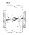
- Fig. 3 shows a throttle body in cross-section with the two-piece throttle, a two-piece elastic compensating element and a first punch and a second stamp.
- the throttle body 2 is in cross section shown.
- the half-way representation A shows the State in which the elastic compensation element 4a still has a certain distance from the throttle body 2.
- the half figure B is the elastic Compensation element 4b directly to the inner wall of the Throttle body 2 on.
- the method for Completing the throttle body 2 is in a first Step a lower part 1b of a two-part throttle valve first fixed to the throttle shaft 3.
- a second Step is at least one elastic compensation element 4a, 4b placed on the lower part 1b.
- a third step is the upper part 1a of the two-part throttle valve 1 on the at least one elastic compensation element 4a, 4b placed and fixed to the throttle shaft. This state shows the half-view A. According to FIG.
- the elastic Compensation elements 4a, 4b executed in one piece and have two opposite breakthroughs 4 'on, the half- or are circular in shape and whose inner diameter is almost the outer diameter of the throttle shaft 3 corresponds. If such an elastic compensation element 4a, 4b used, the second step of the method and the elastic compensation element 4a, 4b is in front of the first Step in a preliminary step with the two opposite ones Breakthroughs 4 'pushed onto the throttle shaft 3. Subsequently, the first step takes place at the lower part 1b of the two-part throttle valve 1 at the Throttle valve shaft 3 is fixed.
- a fourth step is through the lower part 1b a medium between the lower part 1b and the upper part 1a and the at least one elastic compensation element 4b the passage opening 1b 'introduced in the arrow direction.
- gases can be used as a medium become.
- the throttle body 2 is in cross section shown in section 1 A according to section A-A.
- the two opposite openings 4 'of the one-piece Compensating elements 4a, 4b are only dashed shown to illustrate that the elastic Compensating elements 4a, 4b also separated can be used in two parts. In this case it is required, for example, in the lower part 1b of the two-part Throttle valve 1 a further passage opening 1b "to create the medium in a corresponding way, as shown in Fig. 2.
- At least one elastic compensating element 4a, 4b in one piece is designed and two opposite breakthroughs 4 ' it is possible that these also in the Bearing holes of the bearings 3a, 3b protrude, creating a Air seal for shaft breakdown in an advantageous manner can be achieved.
- the throttle body 2 is in cross section shown.
- the fixation of the lower part 1b and the Upper part 1a of the two-part throttle valve 1 at the Throttle valve shaft 3 is effected by pressing a first Stamp 6 and a second stamp 5, the two sides in the throttle body 2 are introduced.
- the first stamp 6 has a supply channel 7, through which the medium can be introduced.
- the two-part throttle valve 1 facing the end of the supply channel 7 opens directly into the Passage opening 1b 'of the lower part 1b of the two-part Throttle valve 1.
- the first punch 6 and the second punch 5 lie sealingly against the inner wall of the throttle body. 2 at. However, it is also possible, the second punch 5 with corresponding channels (not shown) for the supply of Media or to provide ventilation.
Landscapes
- Engineering & Computer Science (AREA)
- General Engineering & Computer Science (AREA)
- Mechanical Engineering (AREA)
- Chemical & Material Sciences (AREA)
- Combustion & Propulsion (AREA)
- Manufacturing & Machinery (AREA)
- Lift Valve (AREA)
- Control Of Throttle Valves Provided In The Intake System Or In The Exhaust System (AREA)
Description
Claims (11)
- Verfahren zum Abschließen eines Drosselklappenstutzens (2), bei dem in einem ersten Schritt ein Unterteil (1b) einer zweiteiligen Drosselklappe (1) an einer Drosselklappenwelle (3) fixiert wird, in einem zweiten Schritt mindestens ein elastisches Ausgleichselement (4a, 4b) auf das Unterteil (1b) aufgelegt wird, in einem dritten Schritt ein Oberteil (1a) der zweiteiligen Drosselklappe (1) auf das mindestens eine elastische Ausgleichselement (4a, 4b) aufgelegt und an der Drosselklappenwelle (3) fixiert wird, in einem vierten Schritt durch das Unterteil (1b) oder das Oberteil (1a) ein Medium zwischen das Unterteil (1b) und das Oberteil (1a) und das mindestens eine elastische Ausgleichselement (4a, 4b) eingebracht und das mindestens eine elastische Ausgleichselement (4a, 4b) an die Innenwand des Drosselklappenstutzens (2) angedrückt wird und in einem fünften Schritt das an die Innenwand des Drosselklappenstutzens (2) angedrückte, mindestens eine elastische Ausgleichselement (4a, 4b) mit dem Unterteil (1b) und dem Oberteil (1a) der zweiteiligen Drosselklappe (1) verbunden wird.
- Verfahren nach Anspruch 1, bei dem die Fixierung des Unterteils (1b) und des Oberteils (1a) der zweiteiligen Drosselklappe (1) an der Drosselklappenwelle (3) durch Andrücken eines ersten Stempels (6) und eines zweiten Stempels (5) erfolgt, die beidseitig in den Drosselklappenstutzen (2) eingebracht werden.
- Verfahren nach Anspruch 1 oder Anspruch 2, bei dem als Medium ein Montageschaum eingebracht wird.
- Verfahren nach einem der Ansprüche 1 bis 3, bei dem das elastische Ausgleichselement (4a, 4b) einteilig ausgeführt ist und zwei gegenüberliegende Durchbrüche (4') aufweist und bei dem der zweite Schritt entfällt und das elastische Ausgleichselement (4a, 4b) vor dem ersten Schritt in einem Vorschritt mit den zwei gegenüberliegenden Durchbrüchen (4') auf die Drosselklappenwelle (3) aufgeschoben wird.
- Verfahren nach einem der Ansprüche 1 bis 4, bei dem eine zweiteilige Drosselklappe (1) aus Metall und mindestens ein elastisches Ausgleichselement (4a, 4b) aus Kunststoff eingesetzt werden.
- Verfahren nach einem der Ansprüche 1 bis 4, bei dem eine zweiteilige Drosselklappe (1) aus Kunststoff und mindestens ein elastisches Ausgleichselement (4a, 4b) aus Kunststoff eingesetzt werden.
- Verfahren nach Anspruch 5 oder 6, bei dem als Kunststoffe Polyamid-6 eingesetzt wird.
- Verfahren nach einem der Ansprüche 1 bis 4, bei dem eine zweiteilige Drosselklappe (1) aus Aluminium und mindestens ein elastisches Ausgleichselement (4a, 4b) aus Aluminium eingesetzt werden.
- Verfahren nach einem der Ansprüche 1 bis 8, bei dem das an die Innenwand des Drosselklappenstutzens (2) angedrückte, mindestens eine elastische Ausgleichselement (4a, 4b) mit dem Unterteil (1b) und dem Oberteil (1a) der zweiteiligen Drosselklappe (1) durch Kleben verbunden wird, wobei der Klebstoff im Vorschritt oder im zweiten Schritt oder im dritten Schritt auf das Unterteil (1b) oder das Oberteil (1a) oder das mindestens eine elastische Ausgleichselement (4a, 4b) aufgegeben wird.
- Verfahren nach einem der Ansprüche 1 bis 4, 6 bis 8, bei dem das Verbinden des an die Innenwand des Drosselklappenstutzens (2) angedrückten, mindestens einen elastischen Ausgleichselements (4a, 4b) mit dem Unterteil (1b) und dem Oberteil (1a) der zweistufigen Drosselklappe (1) durch Lasern erfolgt.
- Verfahren nach einem der Ansprüche 1 bis 8, bei dem das Verbinden des an die Innenwand des Drosselklappenstutzens (2) angedrückten, mindestens einen elastischen Ausgleichselements (4a, 4b) mit dem Unterteil (1b) und dem Oberteil (1a) der zweiteiligen Drosselklappe (1) allein durch den als Medium eingesetzten Montageschaum erfolgt.
Applications Claiming Priority (3)
| Application Number | Priority Date | Filing Date | Title |
|---|---|---|---|
| DE10240910A DE10240910A1 (de) | 2002-09-04 | 2002-09-04 | Verfahren zum Abschließen eines Drosselklappenstutzens |
| DE10240910 | 2002-09-04 | ||
| PCT/DE2003/002782 WO2004025104A1 (de) | 2002-09-04 | 2003-08-21 | Verfahren zum abschliessen eines drosselklappenstutzens |
Publications (2)
| Publication Number | Publication Date |
|---|---|
| EP1534946A1 EP1534946A1 (de) | 2005-06-01 |
| EP1534946B1 true EP1534946B1 (de) | 2005-12-21 |
Family
ID=31724345
Family Applications (1)
| Application Number | Title | Priority Date | Filing Date |
|---|---|---|---|
| EP03750284A Expired - Lifetime EP1534946B1 (de) | 2002-09-04 | 2003-08-21 | Verfahren zum abschliessen eines drosselklappenstutzens |
Country Status (6)
| Country | Link |
|---|---|
| US (1) | US20060208212A1 (de) |
| EP (1) | EP1534946B1 (de) |
| JP (1) | JP4027369B2 (de) |
| KR (1) | KR100709805B1 (de) |
| DE (2) | DE10240910A1 (de) |
| WO (1) | WO2004025104A1 (de) |
Families Citing this family (10)
| Publication number | Priority date | Publication date | Assignee | Title |
|---|---|---|---|---|
| US7624716B2 (en) | 2005-01-25 | 2009-12-01 | Aisan Kogyo Kabushiki Kaisha | Butterfly valve type throttle valve of internal combustion engine |
| JP4749898B2 (ja) | 2006-03-15 | 2011-08-17 | 愛三工業株式会社 | 蝶弁式絞り弁 |
| KR101402265B1 (ko) * | 2006-08-14 | 2014-06-02 | 보르그워너 인코퍼레이티드 | 저력형 고착방지 스로틀 밸브 |
| DE102007007603B3 (de) * | 2007-02-13 | 2008-08-21 | Alstom Technology Ltd. | Vorrichtung und Verfahren zum Betreiben einer mit wenigstens einer Kohlemahlanlage betriebenen Feuerungsanlage |
| USD686297S1 (en) * | 2011-06-21 | 2013-07-16 | Metso Automation Usa Inc. | Valve position communications and control module |
| DE102013216250A1 (de) * | 2013-08-15 | 2015-02-19 | Behr Gmbh & Co. Kg | Klappe für einen Luftführungskanal sowie ein Verfahren zur Herstellung der Klappe |
| CN104776229A (zh) * | 2015-03-31 | 2015-07-15 | 苏州福润机械有限公司 | 一种调风阀 |
| CN104776233A (zh) * | 2015-03-31 | 2015-07-15 | 苏州市华宁机械制造有限公司 | 一种遥控风阀 |
| CN104776230A (zh) * | 2015-03-31 | 2015-07-15 | 苏州福润机械有限公司 | 一种电动风阀 |
| CN106763815A (zh) * | 2016-11-28 | 2017-05-31 | 韦尚仁 | 节流阀 |
Family Cites Families (18)
| Publication number | Priority date | Publication date | Assignee | Title |
|---|---|---|---|---|
| US1591903A (en) * | 1923-07-07 | 1926-07-06 | William M White | Valve |
| US3111300A (en) * | 1960-05-12 | 1963-11-19 | Sr Claude T Boone | Butterfly valve structure |
| GB1141426A (en) * | 1967-02-22 | 1969-01-29 | Hartwig George Binder | Improvements in or relating to butterfly valves |
| US3902697A (en) * | 1973-09-27 | 1975-09-02 | Milwaukee Valve | Butterfly valve |
| US3961405A (en) * | 1973-09-27 | 1976-06-08 | Milwaukee Valve Company, Inc. | Method of fabricating a butterfly valve |
| BR7505730A (pt) * | 1974-09-12 | 1976-08-03 | Panamera Ag | Disco de valvula para uma valvula borboleta;valvula borboleta processo para centrar um anel de vedacao de uma valvula borboleta e processo para vedar uma valvula borboleta |
| GB1544104A (en) * | 1976-02-23 | 1979-04-11 | Shell Int Research | Butterfly valves |
| DE3643948A1 (de) * | 1986-12-22 | 1988-06-23 | Vdo Schindling | Drosselklappenstutzen fuer eine brennkraftmaschine |
| JP2698793B2 (ja) * | 1987-03-20 | 1998-01-19 | 株式会社 日本気化器製作所 | エンジン用吸気絞り弁 |
| US5098064A (en) * | 1990-02-16 | 1992-03-24 | Siemens Automotive L.P. | Engine throttle blade sealing |
| EP0494344A1 (de) * | 1991-01-09 | 1992-07-15 | Firma Carl Freudenberg | Dichtsystem für Drosselklappenkonstruktion mit Vollwelle |
| DE19516927A1 (de) * | 1995-05-09 | 1996-11-14 | Mann & Hummel Filter | Drosselklappendichtung |
| US5902426A (en) * | 1997-08-27 | 1999-05-11 | Siemens Canada Limited | Process for manufacturing an air flow valve |
| DE19819364B4 (de) * | 1998-04-30 | 2006-10-12 | Robert Bosch Gmbh | Drosselklappe |
| JP2000210984A (ja) * | 1999-01-21 | 2000-08-02 | Ge Plastics Japan Ltd | 空気流量制御装置およびその成形方法ならびにその成形型 |
| DE19936456A1 (de) * | 1999-08-03 | 2001-02-08 | Mann & Hummel Filter | Ventil |
| US6589380B2 (en) * | 2001-02-07 | 2003-07-08 | Delphi Technologies, Inc. | Laser welded air control valve and method |
| DE10140394A1 (de) * | 2001-08-23 | 2003-03-06 | Siemens Ag | Drosselklappenstutzen für einen Verbrennungsmotor |
-
2002
- 2002-09-04 DE DE10240910A patent/DE10240910A1/de not_active Withdrawn
-
2003
- 2003-08-21 JP JP2004534978A patent/JP4027369B2/ja not_active Expired - Fee Related
- 2003-08-21 WO PCT/DE2003/002782 patent/WO2004025104A1/de not_active Ceased
- 2003-08-21 DE DE50302021T patent/DE50302021D1/de not_active Expired - Lifetime
- 2003-08-21 KR KR1020057003690A patent/KR100709805B1/ko not_active Expired - Fee Related
- 2003-08-21 EP EP03750284A patent/EP1534946B1/de not_active Expired - Lifetime
-
2006
- 2006-03-27 US US11/389,042 patent/US20060208212A1/en not_active Abandoned
Also Published As
| Publication number | Publication date |
|---|---|
| KR20050042489A (ko) | 2005-05-09 |
| EP1534946A1 (de) | 2005-06-01 |
| KR100709805B1 (ko) | 2007-04-23 |
| JP2005537435A (ja) | 2005-12-08 |
| JP4027369B2 (ja) | 2007-12-26 |
| WO2004025104A1 (de) | 2004-03-25 |
| US20060208212A1 (en) | 2006-09-21 |
| DE50302021D1 (de) | 2006-01-26 |
| DE10240910A1 (de) | 2004-03-18 |
Similar Documents
| Publication | Publication Date | Title |
|---|---|---|
| DE102006007914B4 (de) | Verschlussstopfen mit Druckausgleichskammer | |
| EP0797858B1 (de) | Elektromotor mit Membran für den Druckausgleich | |
| EP2088034B1 (de) | Säulenblende für ein Kraftfahrzeug | |
| EP1931176A1 (de) | Eine elektrische Heizvorrichtung und Verfahren zur Herstellung derselben | |
| DE102008033307A1 (de) | Befestigungsvorrichtung | |
| EP1675766A1 (de) | Verbundbauteil, insbesondere querträger | |
| DE102020117921A1 (de) | Mehrteilig buchsenartiger Einklebehalter | |
| DE10240910A1 (de) | Verfahren zum Abschließen eines Drosselklappenstutzens | |
| EP2428137A1 (de) | Beschlag | |
| EP4105497B1 (de) | Haltevorrichtung und verfahren zu deren anbringung | |
| DE102022115697A1 (de) | Ventilgehäuse mit Dichtungsaufnahmetaschen eines KFZ-Wegeventils zum Einstellen einer Fluidströmung | |
| EP1780425B1 (de) | Verbindungselement | |
| DE102009032243A1 (de) | Verschlussstopfen zum Verschließen einer Öffnung | |
| DE102015114238A1 (de) | Anbindungssystem und Verfahren zur Befestigung eines Bauteils an einer Fahrzeugkarosserie | |
| DE3011386A1 (de) | Fahrzeugkarosserie, insbesondere fuer personenkraftwagen | |
| EP1530695B1 (de) | Verfahren zum abschliessen eines drosselklappenstutzens | |
| DE102004006555B4 (de) | Drosselklappenvorrichtung | |
| DE10231274A1 (de) | Einsatzteil für eine Wandöffnung, insbesondere an einer Fahrzeugkarosserie | |
| DE102017211291B4 (de) | Fensterschachtleistenanordnung sowie Verfahren zum Herstellen einer Fensterschachtleistenanordnung | |
| DE10311207B4 (de) | Ausrücklager | |
| WO2010031622A1 (de) | Filtereinrichtung für verbrennungsmotoren | |
| DE102009008660A1 (de) | Fügeverbindung und Verfahren zu deren Herstellung | |
| EP1534491A1 (de) | Verfahren zum abschliessen eines drosselklappenstutzens | |
| DE202013001061U1 (de) | Haltenocken | |
| DE102021209274A1 (de) | Gehäusewandung und Herstellungsverfahren |
Legal Events
| Date | Code | Title | Description |
|---|---|---|---|
| PUAI | Public reference made under article 153(3) epc to a published international application that has entered the european phase |
Free format text: ORIGINAL CODE: 0009012 |
|
| 17P | Request for examination filed |
Effective date: 20050210 |
|
| AK | Designated contracting states |
Kind code of ref document: A1 Designated state(s): AT BE BG CH CY CZ DE DK EE ES FI FR GB GR HU IE IT LI LU MC NL PT RO SE SI SK TR |
|
| GRAP | Despatch of communication of intention to grant a patent |
Free format text: ORIGINAL CODE: EPIDOSNIGR1 |
|
| GRAS | Grant fee paid |
Free format text: ORIGINAL CODE: EPIDOSNIGR3 |
|
| GRAA | (expected) grant |
Free format text: ORIGINAL CODE: 0009210 |
|
| AK | Designated contracting states |
Kind code of ref document: B1 Designated state(s): DE FR IT |
|
| RBV | Designated contracting states (corrected) |
Designated state(s): DE FR IT |
|
| REF | Corresponds to: |
Ref document number: 50302021 Country of ref document: DE Date of ref document: 20060126 Kind code of ref document: P |
|
| ET | Fr: translation filed | ||
| PLBE | No opposition filed within time limit |
Free format text: ORIGINAL CODE: 0009261 |
|
| STAA | Information on the status of an ep patent application or granted ep patent |
Free format text: STATUS: NO OPPOSITION FILED WITHIN TIME LIMIT |
|
| 26N | No opposition filed |
Effective date: 20060922 |
|
| PGFP | Annual fee paid to national office [announced via postgrant information from national office to epo] |
Ref country code: IT Payment date: 20090819 Year of fee payment: 7 |
|
| PG25 | Lapsed in a contracting state [announced via postgrant information from national office to epo] |
Ref country code: IT Free format text: LAPSE BECAUSE OF NON-PAYMENT OF DUE FEES Effective date: 20100821 |
|
| REG | Reference to a national code |
Ref country code: FR Ref legal event code: TP |
|
| PGFP | Annual fee paid to national office [announced via postgrant information from national office to epo] |
Ref country code: FR Payment date: 20120906 Year of fee payment: 10 Ref country code: DE Payment date: 20120831 Year of fee payment: 10 |
|
| PG25 | Lapsed in a contracting state [announced via postgrant information from national office to epo] |
Ref country code: DE Free format text: LAPSE BECAUSE OF NON-PAYMENT OF DUE FEES Effective date: 20140301 |
|
| REG | Reference to a national code |
Ref country code: DE Ref legal event code: R119 Ref document number: 50302021 Country of ref document: DE Effective date: 20140301 |
|
| REG | Reference to a national code |
Ref country code: FR Ref legal event code: ST Effective date: 20140430 |
|
| PG25 | Lapsed in a contracting state [announced via postgrant information from national office to epo] |
Ref country code: FR Free format text: LAPSE BECAUSE OF NON-PAYMENT OF DUE FEES Effective date: 20130902 |