EP1534441B1 - Method and plant for the hot rolling of rails - Google Patents
Method and plant for the hot rolling of rails Download PDFInfo
- Publication number
- EP1534441B1 EP1534441B1 EP03765060A EP03765060A EP1534441B1 EP 1534441 B1 EP1534441 B1 EP 1534441B1 EP 03765060 A EP03765060 A EP 03765060A EP 03765060 A EP03765060 A EP 03765060A EP 1534441 B1 EP1534441 B1 EP 1534441B1
- Authority
- EP
- European Patent Office
- Prior art keywords
- rolling
- stand
- universal
- rolling passage
- passage
- Prior art date
- Legal status (The legal status is an assumption and is not a legal conclusion. Google has not performed a legal analysis and makes no representation as to the accuracy of the status listed.)
- Revoked
Links
- 238000000034 method Methods 0.000 title claims abstract description 35
- 238000005098 hot rolling Methods 0.000 title description 4
- 238000005096 rolling process Methods 0.000 claims abstract description 125
- 238000007688 edging Methods 0.000 claims abstract description 31
- 238000004519 manufacturing process Methods 0.000 claims abstract description 7
- 230000002441 reversible effect Effects 0.000 claims abstract description 5
- 238000011144 upstream manufacturing Methods 0.000 claims abstract description 5
- 230000009467 reduction Effects 0.000 claims description 19
- 230000000694 effects Effects 0.000 description 3
- 230000008901 benefit Effects 0.000 description 2
- 230000009471 action Effects 0.000 description 1
- 230000008859 change Effects 0.000 description 1
- 238000009749 continuous casting Methods 0.000 description 1
- 238000001816 cooling Methods 0.000 description 1
- 230000010339 dilation Effects 0.000 description 1
- 238000009826 distribution Methods 0.000 description 1
- 238000009434 installation Methods 0.000 description 1
- 239000000463 material Substances 0.000 description 1
- 239000002184 metal Substances 0.000 description 1
- 230000008569 process Effects 0.000 description 1
- 230000000284 resting effect Effects 0.000 description 1
- 238000007669 thermal treatment Methods 0.000 description 1
- 230000009466 transformation Effects 0.000 description 1
Images



Classifications
-
- B—PERFORMING OPERATIONS; TRANSPORTING
- B21—MECHANICAL METAL-WORKING WITHOUT ESSENTIALLY REMOVING MATERIAL; PUNCHING METAL
- B21B—ROLLING OF METAL
- B21B1/00—Metal-rolling methods or mills for making semi-finished products of solid or profiled cross-section; Sequence of operations in milling trains; Layout of rolling-mill plant, e.g. grouping of stands; Succession of passes or of sectional pass alternations
- B21B1/08—Metal-rolling methods or mills for making semi-finished products of solid or profiled cross-section; Sequence of operations in milling trains; Layout of rolling-mill plant, e.g. grouping of stands; Succession of passes or of sectional pass alternations for rolling structural sections, i.e. work of special cross-section, e.g. angle steel
- B21B1/085—Rail sections
-
- B—PERFORMING OPERATIONS; TRANSPORTING
- B21—MECHANICAL METAL-WORKING WITHOUT ESSENTIALLY REMOVING MATERIAL; PUNCHING METAL
- B21B—ROLLING OF METAL
- B21B31/00—Rolling stand structures; Mounting, adjusting, or interchanging rolls, roll mountings, or stand frames
- B21B31/02—Rolling stand frames or housings; Roll mountings ; Roll chocks
- B21B2031/026—Transverse shifting the stand
-
- B—PERFORMING OPERATIONS; TRANSPORTING
- B21—MECHANICAL METAL-WORKING WITHOUT ESSENTIALLY REMOVING MATERIAL; PUNCHING METAL
- B21B—ROLLING OF METAL
- B21B2265/00—Forming parameters
- B21B2265/14—Reduction rate
Definitions
- the present invention refers to a method and a plant for the production by hot rolling of objects such as metallic beams, in particular railway rails and similar rollable materials.
- the rolling operation for a rail generally comprises a break down operation of the ingot or billet in one or more break down stands, optionally the passage in an intermediate working section and then a finishing operation in a finishing stage.
- JP-A-3086301 discloses a rail rolling method comprising a pass in rough rolling mill, in a universal rolling mill, in an edging mill, a second universal rolling mill and a final rolling mill.
- a problem underlying the present invention is to provide a method and a plant, for rails rolling, able to produce rails with a higher quality, in terms of dimensional and surface tolerances, while limiting the number of rolling stands.
- Such a problem is solved, according to a first aspect of the present invention, by a method for the production of rails and similar products according to claim 1.
- a second aspect of the present invention the problem indicated in more detail above is solved by providing a rolling plant according to claim 11.
- the limited number of stands produces a lower initial investment cost and a lower cost for the transformation of the product: In fact, being able to perform the rolling with two or three stands rolling simultaneously the same bar at global temperatures higher than in stands not rolling the same bar, and it is therefore possible to reduce the number of rolling passages.
- a method for the production of rails and similar products through rolling comprising the finishing operation of a bar transformed into a semi-worked rail, characterised by the fact that said finishing operation comprises a rolling passage in a universal stand fitted with a first vertical roll able to work the base of said rail, and a second vertical roll able to work the head (T) of said rail, and said first and second vertical rolls are able to roll said head (T) and said base (B) simultaneously.
- Such a method of finishing allows the making of rails with better dimensional precision, in particular the height and shape of the head of the rail finished.
- Preferred embodiments are also provided which allow the attainment of good surface finishing and further improve the dimensional precision of the rolled rail. Finishing methods according to this further aspect of the present invention can be used both in combination with intermediate rolling methods, according to the foregoing aspects of the present invention, described more above, and in combination with rail intermediate working methods according to the known art.
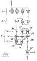
- Figure 1 schematically shows a preferred embodiment of a hot rolling plant for railway rails according to the present invention.
- the bars produced for example from a continuous casting plant (not shown) are firstly rough rolled in a first group of break down stands 1, and optionally in a second group of break down stands 2; then reach an intermediate section, indicated globally by numeral 3. Emerging from said intermediate working section 3, the bars are sent to a finishing station consisting of finishing stand 4 and from this to the successive working stations (plate cooling, thermal treatments etc.).
- finishing stand or “finishing station” means the stand of the rolling line which performs the last rolling passage, performing the last dimensional adjustments on the rail.
- the intermediate working section 3 comprises, in upstream - downstream direction along the bar rolling line, a first universal stand 30, a second universal stand 32, a two-high edging stand 31 placed between the first and second universal stands 30, 32.
- the first and second universal stands 30, 32 and the high edging stand 31 are reversible and located along a single rolling axis, at such distances from each other as to engage all three simultaneously the same bar during rolling (except in the case in which one stand is performing a "dummy" passage, in which the stands simultaneously enaging a bar will be at most two).
- the distances between the horizontal rolls of the first and second universal stands 30, 32, and the high edging stand 31 are as close as possible: this allows performing the various rolling passages at temperatures on average that are higher, reducing the wear of the rolls or, equivalently, allowing higher reduction ratios at each passage and/or a lower number of passages (in the particular embodiment described it has been possible to reduce the passages to just three).
- the rolling section 3 performs the rolling of the semi-worked bar according to the following method, outlined in Figure:
- the semi-worked bar is subjected to a first rolling passage U1 in the second universal stand 32 -the rolls of the first universal stand 30 are initially opened and therefore perform a first dummy passage D1; then the direction of advancement of the bar is inverted and the bar for working passes again in the intermediate rolling section 3 undergoing a first rolling passage E1 in a first working groove of the high edging stand 31, and then a first passage U2 in the first universal stand 30.
- the high edging stand 31 is mobile between different positions, so as to allow the positioning, along the rolling axis of the two universal stands 30, 32, of different grooves or rolling grooves to make different high edging passages.
- the first rolling passage U1 in the second universal stand 32 is carried out with a reduction ratio ⁇ 1 greater than the reduction ratio ⁇ 2 of the first rolling passage U2 in the first universal stand 30, preferably assuming ⁇ 1 approximately equal to 20% and p2 approximately equal to 16%; however such values can be varied and adapted as a function of the specific needs (such as for example shape and dimensions of the rails to roll, temperature etc.).
- ⁇ 1 is selected from between approx. 10% and approx. 30%
- p2 is selected from between approx. 3% and approx. 25%.
- the bar before undergoing the first rolling passage U1 in the universal stand 32, the bar originates from the two break down mills 1 and 2 is further broken down with a rolling passage E2 in a second rolling groove of the high edging stand 31: if present, the intermediate section 3 at such a distance from the break down mill 1, 2 so that the bar, when being worked in the intermediate section 3 is no longer held by the rolls of the break down mills 1, 2,
- the operation E2 can be performed in the shadow of other operations of such break down mills 1, 2 suppressing a working passage from them and reducing the overall rolling time.
- the bar passes again, in a downstream - upstream direction, the intermediate working section 3, following the reversal of movement of the next bar to the first rolling U1 in the second universal stand 32 and prior to the first rolling passage E1 in the high edging stand 31, the bar is subjected to a second rolling passage U3 in the second universal stand 32 (to carry out the passage U3, following the passage U1 the rolls of the stand 32 are brought closer): as said before, the first rolling passage U2 in the first universal stand 30, the first rolling passage E1 in the high edging stand 31 and the second rolling passage U3 in the second universal stand 32 can be carried out with the three stands 30, 31, 32 simultaneously holding the bar (rails generally have final lengths varying from 60 m to over 100 m; the crop ends used to make spares and other extra elements have shorter lengths instead).
- the rolling passage U3 is carried out with a reduction ratio p3 comprised between around 10% and around 30%, and in particular approximately equal to 16%
- the rolling passage U4 is carried out with a reduction ratio p4 comprised between around 3% and around 20%, and in particular approximately equal to 8%.
- the break down and the hardest rolling passages U1 (and optionally U3), with the largest reduction ratios, are only carried out in the second universal stand 32, whilst the passages U2 (and optionally U4) which, with smaller reduction ratios, are all carried out in the first universal stand 30: in this way the greatest wear of the break down operations and the initial deformations U1, U3 involve only the second universal stand 32, whilst the successive rolling passages U2, U4 -which can be considered the pre-finishing passages- are exclusively carried out in the first universal stand 30, which is therefore subjected to less wear and manages to ensure tolerances -of shape and surface finishing- sufficiently precise on the bar emerging from section 3, for a longer working lifetime with respect to plants in which both break down and rough rolling passages and the final pre-finishing passages are performed in an intermediate rolling section on the same universal stand: in fact, in the working cycle of Figure 2, the first universal stand 30 compensates for the deviations in shape which the bar receives from the second universal stand 32 which deteriorat
- the surface finishing of the rolled rail with the methods according to the present invention are better:
- the reduced wear during working, of the stand rolls 30 enables to reach longer periods of time of smoother surfaces of the rolled rails, with respect to the rolling plants of known type.
- the structure of the intermediate section 3 substantially only of three stands, does not require excessively complex roll speed control systems; re-equipping times can be reduced and it is simpler to administer the production of small batches.
- the finishing station 4 is at such a distance, from the intermediate section 3, that a bar is never held simultaneously in a section three stand 3 and the finishing station 4; this, in addition to allowing simultaneously carrying out, and with less dead time, the intermediate rolling and the finishing, eliminates the bar deformations which would occur if this was held both in section 3 and in the station 4: in such a case in fact, the speed of the stands 30, 31, 32 and the finishing stands 4 even if controlled with appropriate control systems, would be however subject to relative slippages more or less important, from which there would be dilation, deformations and in general dimensional variations of the bar.
- the finishing station 4 can comprise, as is currently normal practice, a semi-universal rolling stand (i.e. with two horizontal rolls 40, 41 and one vertical roll 42, Figure 3; the vertical roll 42 rolls and finishes the lower surface of the base of resting of the rail) or also a high edging stand (Figure 4).
- a semi-universal rolling stand i.e. with two horizontal rolls 40, 41 and one vertical roll 42, Figure 3; the vertical roll 42 rolls and finishes the lower surface of the base of resting of the rail
- a high edging stand Figure 4
- the finishing station 4 can advantageously comprise a universal stand with two horizontal rolls 400, 401 and two vertical rolls 402, 403. where the vertical roll 402 works and finishes the base of the rail B, whilst the second vertical roll works and refinishes the area of the head T of the semi-worked rail; the two vertical rolls 402, 403 refinish the base and head of the rail working simultaneously.
- the head T of a rail comprises a rollable central surface T1, on which the wheels of the railway vehicle rest, and the two lateral flanks T2, T3 substantially rectilinearly oriented or vertically or with a slight inclination with respect to the vertical when the rail is installed; on the lateral flanks T2, T3 the wheels of the railway vehicles laterally rest.
- central rollable surfaces T1 and the two lateral flanks T2, T3 are joined by two curved areas T4, T5.
- the vertical rolling roll 403, which deforms and refinishes the head T of the rail, comprises a rolling groove 404 able to plastically deform and refinish the head T;
- the groove 404 comprises a central area -able to plastically deform and refinish the central rollable section T1 of the head- and two lateral surfaces located to the sides of said central zone and able to retain and shape the lateral flanks T4, T5 of the head T of the rail.
- the other roll 402 has a normal flat rolling surface to finish the lower face of the base B of the rail.
- the shape of the groove 404 allows to retain and shape with greater precision not just the central rollable area T1 of the head T of the rail, but also the flanksT4, T5 of the head.
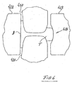
- Figure 6 shows a further embodiment of a universal finishing stand with two vertical rolls 422, 423 developed by the applicant:
- the groove 424 which shapes the head T of the rail is less deep and deprived of the lateral flanks able to shape and retain the lateral flanks T2, T3 of the head of the rail; the groove 424 rolls and finishes only the central area T1 of the head of the rail; in this way the problem of slipping due to the rotational speed gradient along the surface of the groove 404 is overcome.
- the finishing stand of Figure 6 is also itself fitted with a second roll 422 to shape and finish precisely the lower side of the base B of the rail.
- the two vertical roll finishing stands just illustrated can be used as finishing stations not just in the plants realised according to the present invention, but also in mills of a different kind, for example having intermediate sections of known type.
- the finishing passage UF in the stand 4 Independently of the type of stand used for finishing (semi-universal, universal or high edging) preferably the finishing passage UF in the stand 4 ( Figure 1, 2) is performed with a reduction ratio ⁇ F comprised of between around 1% and around 15%, and in particular with a reduction ratio ⁇ F equal to around 2%: such a reduction ratio, particularly small, optionally coupled with the pre-finishing action of the optional passages U2 and U4 carried out as previously described, enables to reach rather precise dimensional and surface finishing tolerances and more constant over time, with respect to the finishing methods of the known art.
- the described embodiments are susceptible to many variations without departing from the scope of the present invention: for example it is possible to change by adding or removing rolling stands to carry out the various passages. If required by the floor space of the building in which the plant is housed the number of passages of the bar through the intermediate section 3 can also be even, and not necessarily uneven as previously described, so that the rail, at the end of the rolling cycle is expelled from the section 3 from the same side as into which it was introduced, rather than crossing the section 3 and continuing downstream.
Landscapes
- Engineering & Computer Science (AREA)
- Mechanical Engineering (AREA)
- Metal Rolling (AREA)
- Heat Treatment Of Articles (AREA)
Abstract
Description
- The present invention refers to a method and a plant for the production by hot rolling of objects such as metallic beams, in particular railway rails and similar rollable materials.
- Hot rolling production of railway rails in appropriate rolling stands is known.
- The rolling operation for a rail generally comprises a break down operation of the ingot or billet in one or more break down stands, optionally the passage in an intermediate working section and then a finishing operation in a finishing stage. The development of high speed railway lines requires tighter working tolerances on the rails than in the case of normal railway line rails.
- JP-A-3086301 discloses a rail rolling method comprising a pass in rough rolling mill, in a universal rolling mill, in an edging mill, a second universal rolling mill and a final rolling mill.
- A problem underlying the present invention is to provide a method and a plant, for rails rolling, able to produce rails with a higher quality, in terms of dimensional and surface tolerances, while limiting the number of rolling stands.
- Such a problem is solved, according to a first aspect of the present invention, by a method for the production of rails and similar products according to
claim 1. According to a second aspect of the present invention, the problem indicated in more detail above is solved by providing a rolling plant according to claim 11. - A further advantage of a method and a plant as described above, besides a good compromise between good dimensional and superficial tolerance and a limited number of rolling stands, is a high productivity.
- The limited number of stands produces a lower initial investment cost and a lower cost for the transformation of the product: In fact, being able to perform the rolling with two or three stands rolling simultaneously the same bar at global temperatures higher than in stands not rolling the same bar, and it is therefore possible to reduce the number of rolling passages.
- Additionally the three stand intermediate rolling section, with regards to controlling the rolls rotation speed and other process parameters, is relatively simple to control.
- According to a further aspect of the present invention, a method for the production of rails and similar products through rolling is described comprising the finishing operation of a bar transformed into a semi-worked rail, characterised by the fact that said finishing operation comprises a rolling passage in a universal stand fitted with a first vertical roll able to work the base of said rail, and a second vertical roll able to work the head (T) of said rail, and said first and second vertical rolls are able to roll said head (T) and said base (B) simultaneously.
- Currently, in the rolling of rails, the finishing passage is performed in semi-universal rolling stands -fitted with a single vertical rolling roll- or, sometimes, in high edging stands.
- Such a method of finishing allows the making of rails with better dimensional precision, in particular the height and shape of the head of the rail finished.
- Preferred embodiments are also provided which allow the attainment of good surface finishing and further improve the dimensional precision of the rolled rail. Finishing methods according to this further aspect of the present invention can be used both in combination with intermediate rolling methods, according to the foregoing aspects of the present invention, described more above, and in combination with rail intermediate working methods according to the known art.
- Further advantages of the present invention will become apparent, to the skilled person, from the following detailed description of an embodiment given by way of non limiting example, with reference to the following figures, of which:
- Figure 1 shows schematically an embodiment of a rolling plant to carry out a method according to the invention;
- Figure 2 shows schematically the sequence of rolling operations carried out in the plant of Figure 1, according to an embodiment of a method according to the invention;
- Figure 3 shows schematically a sectional view of a finishing stand of the plant of Figure 1 according to a first embodiment of a method according to the present invention;
- Figure 4 shows schematically a sectional view of a finishing stand of the plant of Figure 1 according to a second embodiment of a method according to the present invention;
- Figure 5 shows schematically a sectional view of a finishing stand of the plant of Figure 1 according to a third embodiment of a method according to the present invention;
- Figure 6 shows schematically a sectional view of a finishing stand of a plant of Figure 1 according to fourth embodiment of a method according to the present invention.
- In the present description, the expression "reduction ratio" ρ means the ratio (optionally expressed as a percentage) between the reduction which the area S of each bar section is subjected at each rolling passage, and the area of the section of the bar prior to the rolling passage, ρ = (Sprior- Safter)/Sprior.
- Figure 1 schematically shows a preferred embodiment of a hot rolling plant for railway rails according to the present invention.
- The bars produced, for example from a continuous casting plant (not shown) are firstly rough rolled in a first group of break down stands 1, and optionally in a second group of break down
stands 2; then reach an intermediate section, indicated globally bynumeral 3. Emerging from saidintermediate working section 3, the bars are sent to a finishing station consisting of finishingstand 4 and from this to the successive working stations (plate cooling, thermal treatments etc.). - In the present patent application, the expression "finishing stand" or "finishing station" means the stand of the rolling line which performs the last rolling passage, performing the last dimensional adjustments on the rail.
- According to an aspect of the present invention, the intermediate working
section 3 comprises, in upstream - downstream direction along the bar rolling line, a firstuniversal stand 30, a seconduniversal stand 32, a two-high edgingstand 31 placed between the first and seconduniversal stands stand 31 are reversible and located along a single rolling axis, at such distances from each other as to engage all three simultaneously the same bar during rolling (except in the case in which one stand is performing a "dummy" passage, in which the stands simultaneously enaging a bar will be at most two). - Advantageously the distances between the horizontal rolls of the first and second universal stands 30, 32, and the high edging
stand 31 are as close as possible: this allows performing the various rolling passages at temperatures on average that are higher, reducing the wear of the rolls or, equivalently, allowing higher reduction ratios at each passage and/or a lower number of passages (in the particular embodiment described it has been possible to reduce the passages to just three). - According to a first aspect of the present invention, the
rolling section 3 performs the rolling of the semi-worked bar according to the following method, outlined in Figure:
The semi-worked bar is subjected to a first rolling passage U1 in the second universal stand 32 -the rolls of the firstuniversal stand 30 are initially opened and therefore perform a first dummy passage D1; then the direction of advancement of the bar is inverted and the bar for working passes again in the intermediate rollingsection 3 undergoing a first rolling passage E1 in a first working groove of the high edgingstand 31, and then a first passage U2 in the firstuniversal stand 30.
The high edgingstand 31 is mobile between different positions, so as to allow the positioning, along the rolling axis of the two universal stands 30, 32, of different grooves or rolling grooves to make different high edging passages.
Advantageously the first rolling passage U1 in the seconduniversal stand 32 is carried out with a reduction ratio ρ1 greater than the reduction ratio ρ2 of the first rolling passage U2 in the firstuniversal stand 30, preferably assuming ρ1 approximately equal to 20% and p2 approximately equal to 16%; however such values can be varied and adapted as a function of the specific needs (such as for example shape and dimensions of the rails to roll, temperature etc.). Preferably ρ1 is selected from between approx. 10% and approx. 30%, and p2 is selected from between approx. 3% and approx. 25%. - Advantageously, before undergoing the first rolling passage U1 in the
universal stand 32, the bar originates from the two break downmills intermediate section 3 at such a distance from the break downmill intermediate section 3 is no longer held by the rolls of the break downmills mills - Preferably, when the bar passes again, in a downstream - upstream direction, the
intermediate working section 3, following the reversal of movement of the next bar to the first rolling U1 in the seconduniversal stand 32 and prior to the first rolling passage E1 in the high edgingstand 31, the bar is subjected to a second rolling passage U3 in the second universal stand 32 (to carry out the passage U3, following the passage U1 the rolls of thestand 32 are brought closer): as said before, the first rolling passage U2 in the firstuniversal stand 30, the first rolling passage E1 in the high edgingstand 31 and the second rolling passage U3 in the seconduniversal stand 32 can be carried out with the three stands 30, 31, 32 simultaneously holding the bar (rails generally have final lengths varying from 60 m to over 100 m; the crop ends used to make spares and other extra elements have shorter lengths instead). - According to the preferred working cycle outlined in Figure 2, following the first rolling passage U2 in the first universal stand, the direction of advancement of the bar is again inverted and the bar subjected to a second rolling passage U4 in the first universal stand 30 (in the same rolling rolls as the passage U2, but to carry out the passage U4 the rolls of the
stand 30 are brought closer together), and successively a third rolling passage E3 in a third rolling groove of the high edgingstand 31; the rolls of thesecond stand 32 are now opened and do not perform any rolling of the on the bar (second dummy passage D2), which is sent to thefinishing station 4. - Preferably the rolling passage U3 is carried out with a reduction ratio p3 comprised between around 10% and around 30%, and in particular approximately equal to 16%, the rolling passage U4 is carried out with a reduction ratio p4 comprised between around 3% and around 20%, and in particular approximately equal to 8%. According to the preferred working cycle just described, the break down and the hardest rolling passages U1 (and optionally U3), with the largest reduction ratios, are only carried out in the second
universal stand 32, whilst the passages U2 (and optionally U4) which, with smaller reduction ratios, are all carried out in the first universal stand 30: in this way the greatest wear of the break down operations and the initial deformations U1, U3 involve only the seconduniversal stand 32, whilst the successive rolling passages U2, U4 -which can be considered the pre-finishing passages- are exclusively carried out in the firstuniversal stand 30, which is therefore subjected to less wear and manages to ensure tolerances -of shape and surface finishing- sufficiently precise on the bar emerging fromsection 3, for a longer working lifetime with respect to plants in which both break down and rough rolling passages and the final pre-finishing passages are performed in an intermediate rolling section on the same universal stand: in fact, in the working cycle of Figure 2, the firstuniversal stand 30 compensates for the deviations in shape which the bar receives from the seconduniversal stand 32 which deteriorates more quickly. - Also, the surface finishing of the rolled rail with the methods according to the present invention are better: In fact, the reduced wear during working, of the
stand rolls 30 enables to reach longer periods of time of smoother surfaces of the rolled rails, with respect to the rolling plants of known type. - The structure of the
intermediate section 3 substantially only of three stands, does not require excessively complex roll speed control systems; re-equipping times can be reduced and it is simpler to administer the production of small batches. - In comparison to other installations one obtains equal quality and tolerances on the product emerging with a fewer number of stands, and therefore one has a saving on the initial investments.
- The working with reversible stands ensures more uniform temperature distribution over the bar, for example, with respect to a continuous rolling process. Advantageously, the
finishing station 4 is at such a distance, from theintermediate section 3, that a bar is never held simultaneously in a section threestand 3 and thefinishing station 4; this, in addition to allowing simultaneously carrying out, and with less dead time, the intermediate rolling and the finishing, eliminates the bar deformations which would occur if this was held both insection 3 and in the station 4: in such a case in fact, the speed of thestands - The
finishing station 4 can comprise, as is currently normal practice, a semi-universal rolling stand (i.e. with twohorizontal rolls vertical roll 42, Figure 3; thevertical roll 42 rolls and finishes the lower surface of the base of resting of the rail) or also a high edging stand (Figure 4). - According to a preferred embodiment of a method according to the present invention (Figure 5), the
finishing station 4 can advantageously comprise a universal stand with twohorizontal rolls vertical rolls vertical roll 402 works and finishes the base of the rail B, whilst the second vertical roll works and refinishes the area of the head T of the semi-worked rail; the twovertical rolls - The use of a universal stand with two vertical rolls (Figure 5, 6) is a further factor which enables reaching more precise tolerances on the overall height of the rails. Still with reference to Figure 5, generally the head T of a rail comprises a rollable central surface T1, on which the wheels of the railway vehicle rest, and the two lateral flanks T2, T3 substantially rectilinearly oriented or vertically or with a slight inclination with respect to the vertical when the rail is installed; on the lateral flanks T2, T3 the wheels of the railway vehicles laterally rest.
- The central rollable surfaces T1 and the two lateral flanks T2, T3 are joined by two curved areas T4, T5.
- The
vertical rolling roll 403, which deforms and refinishes the head T of the rail, comprises arolling groove 404 able to plastically deform and refinish the head T; Thegroove 404 comprises a central area -able to plastically deform and refinish the central rollable section T1 of the head- and two lateral surfaces located to the sides of said central zone and able to retain and shape the lateral flanks T4, T5 of the head T of the rail. - The
other roll 402 has a normal flat rolling surface to finish the lower face of the base B of the rail. - The shape of the
groove 404 allows to retain and shape with greater precision not just the central rollable area T1 of the head T of the rail, but also the flanksT4, T5 of the head. - Returning to the rolls of the traditional semi-universal finishing stand of Figure 3, in general the difference between the different speed of rotation of a rolling groove in the different points P1-P10 produces, on the surfaces of the rolled bar, an undesired slipping effect in some areas of the metal of the bar, for this reason the depth of the rolling grooves is not excessively big.
- By comparing the sections of the rolling grooves of the rolls of Figures 3 and 5, one remarks that the rolls of the kind of Figure 5 can be made with
rolling grooves 404 which do not give rise to excessive slipping effects on the surface of the rail; since the slipping effect is increased with reduction in the average diameter of the groove, it is preferable to choose large diameters for thevertical rolls - Figure 6 shows a further embodiment of a universal finishing stand with two
vertical rolls 422, 423 developed by the applicant: - in such an example the
groove 424 which shapes the head T of the rail is less deep and deprived of the lateral flanks able to shape and retain the lateral flanks T2, T3 of the head of the rail; thegroove 424 rolls and finishes only the central area T1 of the head of the rail; in this way the problem of slipping due to the rotational speed gradient along the surface of thegroove 404 is overcome. - The finishing stand of Figure 6 is also itself fitted with a
second roll 422 to shape and finish precisely the lower side of the base B of the rail. - The two vertical roll finishing stands just illustrated can be used as finishing stations not just in the plants realised according to the present invention, but also in mills of a different kind, for example having intermediate sections of known type. Independently of the type of stand used for finishing (semi-universal, universal or high edging) preferably the finishing passage UF in the stand 4 (Figure 1, 2) is performed with a reduction ratio ρF comprised of between around 1% and around 15%, and in particular with a reduction ratio ρF equal to around 2%: such a reduction ratio, particularly small, optionally coupled with the pre-finishing action of the optional passages U2 and U4 carried out as previously described, enables to reach rather precise dimensional and surface finishing tolerances and more constant over time, with respect to the finishing methods of the known art.
- The described embodiments are susceptible to many variations without departing from the scope of the present invention: for example it is possible to change by adding or removing rolling stands to carry out the various passages. If required by the floor space of the building in which the plant is housed the number of passages of the bar through the
intermediate section 3 can also be even, and not necessarily uneven as previously described, so that the rail, at the end of the rolling cycle is expelled from thesection 3 from the same side as into which it was introduced, rather than crossing thesection 3 and continuing downstream.
Claims (12)
- A method for the production of rails and similar products with a rolling plant, wherein the plant comprises a reversible intermediate working station (3), the intermediate working station (3) comprising a first (30), a second universal stand (32) and a high edging stand (31) placed between said first(30) and said second (32) universal stands, a finishing station (4), wherein the intermediate working station (3) is able to receive a pre-rough rolled bar from an appropriate upstream rough rolling station (2) and to deliver it, after having worked it, to said downstream finishing station (4), the method comprising, in the order indicated, the following operations:a first rolling passage (U1) in said second universal stand (32);a first rolling passage (E1) in said high edging stand (31);a first rolling passage (U2) in said first universal stand (30),a rolling passage (UF) in said finishing station (4),characterised by the fact that
the high edging stand (31) is a two-high edging stand,
said first universal (30), high edging (31) and second universal (32) stands are placed at such a distance between each other that said bar can be held simultaneously in all three of said stands (30, 31, 32) during rolling operations,
said first rolling passage (U1) in said second universal stand (32) is performed with a reduction ratio (ρ1) comprised of between around 10% and around 30%, and
said first rolling passage (U2) in said first universal stand (30) is performed with a reduction ratio (ρ2) comprised of between around 3% and around 25%,
said finishing station (4) is placed at such a distance from said intermediate working section (3) that, when said finishing stand works a finishing passage on said bar (UF), said bar is not held in any of the said first universal (30), high edging (31) and second universal (32) stands. - The method according to claim 1, wherein said reduction ratio (ρ1) with which is performed said first rolling passage (U1) in said second universal stand (32) is equal to around 20%, and said reduction ratio (ρ2) with which is performed said first rolling passage (U2) in said first universal stand (30) is equal to around 10%.
- The method according to one or more of the preceding claims, wherein said first rolling passage (U1) in said second universal stand (32) is preceded by a second rolling passage (E2) in said high edging stand (31).
- The method according to one or more of the preceding claims, wherein said following said first rolling passage (U1) in said second universal stand (32) and prior to said first rolling passage (E1) in said high edging stand (31) is carried out on said bar for rolling a second rolling passage (U3) in said second universal stand (32).
- The method according to claim 4, wherein said second rolling passage (U3) in said second universal stand (32) is performed with a reduction ratio (ρ3) comprised of between around 10% and around 30%.
- The method according to one or more of the preceding claims, wherein, following said first rolling passage (U2) in said first universal stand (30), a third rolling passage (E3) in said high edging stand (31) is performed.
- The method according to one or more of the preceding claims, wherein immediately following said first rolling passage (U2) in said first universal stand (30), in said first universal stand (30) is performed a second rolling passage (U4).
- The method according to claim 9, wherein said second rolling passage (U4) carried out in said first universal stand (30) is performed with a reduction ratio (ρ4) comprised of between around 3% and around 20%.
- The method according to one or more of the preceding claims, wherein said third rolling passage (E3) in said high edging stand (31) is successive to said second rolling passage (U4) in said first universal stand (30).
- The method according to one or more of the preceding claims, comprising a series of operations substantially constituted of the following rolling passages, in the sequence indicated:said second rolling passage (E2) in said high edging stand (31) on exiting from said pre-rough rolling station (2)said first rolling passage (U1) in said second universal stand (32),said second rolling passage (U3) in said second universal stand (32),said first rolling passage (E1) in said high edging stand (31),said first rolling passage (U2) in said first universal stand (30),said second rolling passage (U4) in said first universal stand (30),said third rolling passage (E3) in said high edging stand (31),a rolling passage (UF) in said finishing station (4).
- A rolling plant for the implementation of a method according to one or more preceding claims, said plant comprising a reversible intermediate working section (3) able to receive a pre-rough rolled bar from an appropriate upstream rough rolling station (2) and to supply it, after having worked it, to a downstream finishing station (4), where said intermediate working section (3) comprises, located in succession along at least one rolling axis, a first universal stand (30) and a high edging stand (31), comprising a second universal stand (32) located, along said at least one rolling axis, such that said high edging stand (31) is placed between said first and second universal stands (30, 32), characterised in that said three stands (30, 31, 32) are located at such distances from each other that said bar can be held simultaneously in all three said stands (30, 31, 32) during rolling operations and in that the finishing station (4) comprises in turn a finishing stand placed at such a distance from said intermediate working section (3) that, when said finishing stand works a finishing passage on said bar (UF), said bar is not held in any of the said stands (30, 31, 32) of said intermediate working section (3).
- A plant according to claim 11, wherein said three stands (30, 31, 32) of said intermediate rolling section (3) are placed one after the other, without the interposition of further rolling stands.
Applications Claiming Priority (3)
| Application Number | Priority Date | Filing Date | Title |
|---|---|---|---|
| ITMI20021594 | 2002-07-19 | ||
| IT2002MI001594A ITMI20021594A1 (en) | 2002-07-19 | 2002-07-19 | METHOD AND SYSTEM FOR HOT ROLLING OF RAILS |
| PCT/EP2003/007897 WO2004009259A1 (en) | 2002-07-19 | 2003-07-18 | Method and plant for the hot rolling of rails |
Publications (2)
| Publication Number | Publication Date |
|---|---|
| EP1534441A1 EP1534441A1 (en) | 2005-06-01 |
| EP1534441B1 true EP1534441B1 (en) | 2007-06-06 |
Family
ID=30130898
Family Applications (1)
| Application Number | Title | Priority Date | Filing Date |
|---|---|---|---|
| EP03765060A Revoked EP1534441B1 (en) | 2002-07-19 | 2003-07-18 | Method and plant for the hot rolling of rails |
Country Status (9)
| Country | Link |
|---|---|
| US (1) | US20060016236A1 (en) |
| EP (1) | EP1534441B1 (en) |
| CN (1) | CN1299844C (en) |
| AT (1) | ATE363952T1 (en) |
| AU (1) | AU2003250119A1 (en) |
| DE (1) | DE60314256T2 (en) |
| ES (1) | ES2288623T3 (en) |
| IT (1) | ITMI20021594A1 (en) |
| WO (1) | WO2004009259A1 (en) |
Families Citing this family (12)
| Publication number | Priority date | Publication date | Assignee | Title |
|---|---|---|---|---|
| EP1596854A4 (en) * | 2003-02-14 | 2007-06-06 | Childrens Hosp & Res Ct Oak | TREATMENT OF PATHOLOGICAL CONDITIONS ASSOCIATED WITH REDUCED BIOAVAILABILITY OF NITRIC OXIDE, INCLUDING PATHOLOGICAL CONDITIONS CAUSED BY HIGH ACTIVITY OF ARGINASE |
| CN1753008B (en) * | 2005-10-26 | 2011-08-10 | 上海宝信软件股份有限公司 | Method of optimization hot rolling scaduled sequence |
| AP2011005934A0 (en) * | 2009-03-16 | 2011-10-31 | Tata Steel Uk Ltd | A method of rolling rails, apparatus for rolling rails and rail produced according to said method. |
| WO2011063935A2 (en) | 2009-11-26 | 2011-06-03 | Tata Steel Uk Limited | A method of rolling rails, apparatus for rolling rails and rail produced according to said method |
| IT1397191B1 (en) * | 2009-12-01 | 2013-01-04 | Siemens Vai Metals Tech Srl | UNIVERSAL REVERSIBLE TRAIN COMPACT FOR THE PRODUCTION OF LARGE MEDIUM PROFILES. |
| CN101844150B (en) * | 2010-05-18 | 2011-10-05 | 攀钢集团钢铁钒钛股份有限公司 | Rail Universal Rolling Process |
| CN102527714B (en) * | 2011-12-30 | 2015-01-14 | 天津市宁河县隆昌异型轧钢厂 | Rolling method for T-shaped elevator guide rail and rolling pass system |
| CN105414172A (en) * | 2015-12-16 | 2016-03-23 | 武汉科技大学 | A Method for Eliminating Convex Points at the Tails of Concatenated Rails |
| CN105665444B (en) * | 2016-02-26 | 2018-03-06 | 攀钢集团攀枝花钢钒有限公司 | For improving the Universal Pass structure of steel rail rolling Symmetric Mass |
| RU2627140C1 (en) * | 2016-10-10 | 2017-08-03 | Акционерное общество "ЕВРАЗ Объединенный Западно-Сибирский металлургический комбинат", АО "ЕВРАЗ ЗСМК" | Method for rail rolling |
| CN106424138A (en) * | 2016-10-26 | 2017-02-22 | 攀钢集团攀枝花钢钒有限公司 | Layout structure of universal rolling mill and rolling method |
| CN109158424B (en) * | 2018-09-27 | 2023-08-18 | 中重科技(天津)股份有限公司 | Axial locking device for horizontal roller system of super-huge universal rolling mill |
Family Cites Families (10)
| Publication number | Priority date | Publication date | Assignee | Title |
|---|---|---|---|---|
| BE624447A (en) * | 1961-11-22 | |||
| US3583193A (en) * | 1967-12-16 | 1971-06-08 | Nippon Steel Corp | Rolling method and apparatus for producing h-shaped steel products having flanges of different thicknesses and similarly shaped steel products |
| SU623593A1 (en) * | 1974-03-11 | 1978-08-02 | Сибирский Металлургический Институт Имени С.Орджоникидзе | Rail profile rolling method |
| FR2515538B1 (en) * | 1981-11-04 | 1985-05-17 | Sacilor | |
| JPS5921403A (en) * | 1982-06-30 | 1984-02-03 | Nippon Steel Corp | Universal rolling method of rail |
| DE3627729C2 (en) * | 1986-08-16 | 1996-03-07 | Schloemann Siemag Ag | Molded steel rolling mill |
| JPH0386301A (en) * | 1989-08-29 | 1991-04-11 | Nippon Steel Corp | Rail rolling method |
| JP2712846B2 (en) * | 1991-02-08 | 1998-02-16 | 住友金属工業株式会社 | Rolling method and rolling device for section steel |
| DE19618437A1 (en) * | 1996-05-08 | 1997-11-13 | Schloemann Siemag Ag | Method for operating a roll stand system |
| DE19628369A1 (en) * | 1996-07-13 | 1998-01-15 | Schloemann Siemag Ag | Process for rolling finished profiles from a preliminary profile |
-
2002
- 2002-07-19 IT IT2002MI001594A patent/ITMI20021594A1/en unknown
-
2003
- 2003-07-18 ES ES03765060T patent/ES2288623T3/en not_active Expired - Lifetime
- 2003-07-18 DE DE60314256T patent/DE60314256T2/en not_active Revoked
- 2003-07-18 WO PCT/EP2003/007897 patent/WO2004009259A1/en not_active Ceased
- 2003-07-18 EP EP03765060A patent/EP1534441B1/en not_active Revoked
- 2003-07-18 CN CNB038167786A patent/CN1299844C/en not_active Expired - Fee Related
- 2003-07-18 US US10/522,437 patent/US20060016236A1/en not_active Abandoned
- 2003-07-18 AU AU2003250119A patent/AU2003250119A1/en not_active Abandoned
- 2003-07-18 AT AT03765060T patent/ATE363952T1/en not_active IP Right Cessation
Also Published As
| Publication number | Publication date |
|---|---|
| CN1668394A (en) | 2005-09-14 |
| WO2004009259A1 (en) | 2004-01-29 |
| EP1534441A1 (en) | 2005-06-01 |
| CN1299844C (en) | 2007-02-14 |
| WO2004009259A8 (en) | 2004-05-06 |
| ES2288623T3 (en) | 2008-01-16 |
| ITMI20021594A1 (en) | 2004-01-19 |
| ATE363952T1 (en) | 2007-06-15 |
| AU2003250119A8 (en) | 2004-02-09 |
| US20060016236A1 (en) | 2006-01-26 |
| DE60314256T2 (en) | 2008-02-07 |
| AU2003250119A1 (en) | 2004-02-09 |
| DE60314256D1 (en) | 2007-07-19 |
Similar Documents
| Publication | Publication Date | Title |
|---|---|---|
| CN102247981B (en) | Section steel rolling production process | |
| CN104525560B (en) | Effective control method of the 30mm cut deal pitted skins of straight carbon steel/Nb bearing steel 20 | |
| US5904061A (en) | Method of rolling finished sections from a preliminary section | |
| US20060016236A1 (en) | Method and plant for the hot rolling of rails | |
| CN103071673B (en) | Compact universal vertical steel rail milling method | |
| WO2016054851A1 (en) | Production line for rolling hollow steel and roll-forming production method therefor | |
| CN102513370A (en) | Control process for single-stand Steckel mill to produce special-purpose pipeline steel | |
| CN109261714B (en) | Rolling method of symmetrical flat-bulb steel for large shipbuilding | |
| US4860426A (en) | System for rolling continuously cast profiles | |
| CN100515593C (en) | Comprehensive control method for strip edge thickening in common four-high hot strip continuous rolling mill | |
| WO2010105749A2 (en) | A method of rolling rails, apparatus for rolling rails and rail produced according to said method | |
| CN114130815A (en) | Process method for rolling pure titanium coiled plates in small batches | |
| CN102527714B (en) | Rolling method for T-shaped elevator guide rail and rolling pass system | |
| AU2004291230B2 (en) | Rolling mill for hot-rolling metal, in particular, aluminium in addition to hot-rolling method | |
| CN202087575U (en) | Profile steel rolling production line | |
| CN112705569B (en) | Steckel mill production line with ultra-short distance arrangement and rolling process | |
| CN105414177B (en) | A kind of cold rolling super-high strength steel short route production and processing technology and equipment | |
| CN103433276A (en) | Profile steel rolling production line and production method thereof | |
| JPH0386301A (en) | Rail rolling method | |
| CN206936012U (en) | Heavy section steel rolled steel production system | |
| WO2011063935A2 (en) | A method of rolling rails, apparatus for rolling rails and rail produced according to said method | |
| CN110180889B (en) | Orbital rolling production line and orbital rolling process using the same | |
| CN212442554U (en) | Near-net shape rail-shaped blank short-flow continuous casting and rolling production system | |
| CN204220617U (en) | A kind of steekle mill production line preparing roughing mill | |
| KR20120033022A (en) | Method for manufacturing shape steel comprising pre-cooling process and shape steel rolling mill using the same |
Legal Events
| Date | Code | Title | Description |
|---|---|---|---|
| PUAI | Public reference made under article 153(3) epc to a published international application that has entered the european phase |
Free format text: ORIGINAL CODE: 0009012 |
|
| 17P | Request for examination filed |
Effective date: 20050221 |
|
| AK | Designated contracting states |
Kind code of ref document: A1 Designated state(s): AT BE BG CH CY CZ DE DK EE ES FI FR GB GR HU IE IT LI LU MC NL PT RO SE SI SK TR |
|
| AX | Request for extension of the european patent |
Extension state: AL LT LV MK |
|
| DAX | Request for extension of the european patent (deleted) | ||
| GRAP | Despatch of communication of intention to grant a patent |
Free format text: ORIGINAL CODE: EPIDOSNIGR1 |
|
| RIC1 | Information provided on ipc code assigned before grant |
Ipc: B21B 1/08 20060101AFI20061206BHEP |
|
| GRAS | Grant fee paid |
Free format text: ORIGINAL CODE: EPIDOSNIGR3 |
|
| GRAA | (expected) grant |
Free format text: ORIGINAL CODE: 0009210 |
|
| AK | Designated contracting states |
Kind code of ref document: B1 Designated state(s): AT BE BG CH CY CZ DE DK EE ES FI FR GB GR HU IE IT LI LU MC NL PT RO SE SI SK TR |
|
| PG25 | Lapsed in a contracting state [announced via postgrant information from national office to epo] |
Ref country code: LI Free format text: LAPSE BECAUSE OF FAILURE TO SUBMIT A TRANSLATION OF THE DESCRIPTION OR TO PAY THE FEE WITHIN THE PRESCRIBED TIME-LIMIT Effective date: 20070606 Ref country code: CH Free format text: LAPSE BECAUSE OF FAILURE TO SUBMIT A TRANSLATION OF THE DESCRIPTION OR TO PAY THE FEE WITHIN THE PRESCRIBED TIME-LIMIT Effective date: 20070606 Ref country code: FI Free format text: LAPSE BECAUSE OF FAILURE TO SUBMIT A TRANSLATION OF THE DESCRIPTION OR TO PAY THE FEE WITHIN THE PRESCRIBED TIME-LIMIT Effective date: 20070606 |
|
| REG | Reference to a national code |
Ref country code: GB Ref legal event code: FG4D |
|
| REG | Reference to a national code |
Ref country code: CH Ref legal event code: EP |
|
| REG | Reference to a national code |
Ref country code: IE Ref legal event code: FG4D |
|
| REF | Corresponds to: |
Ref document number: 60314256 Country of ref document: DE Date of ref document: 20070719 Kind code of ref document: P |
|
| PG25 | Lapsed in a contracting state [announced via postgrant information from national office to epo] |
Ref country code: SE Free format text: LAPSE BECAUSE OF FAILURE TO SUBMIT A TRANSLATION OF THE DESCRIPTION OR TO PAY THE FEE WITHIN THE PRESCRIBED TIME-LIMIT Effective date: 20070906 |
|
| ET | Fr: translation filed | ||
| NLV1 | Nl: lapsed or annulled due to failure to fulfill the requirements of art. 29p and 29m of the patents act | ||
| REG | Reference to a national code |
Ref country code: CH Ref legal event code: PL |
|
| PG25 | Lapsed in a contracting state [announced via postgrant information from national office to epo] |
Ref country code: BE Free format text: LAPSE BECAUSE OF FAILURE TO SUBMIT A TRANSLATION OF THE DESCRIPTION OR TO PAY THE FEE WITHIN THE PRESCRIBED TIME-LIMIT Effective date: 20070606 |
|
| REG | Reference to a national code |
Ref country code: ES Ref legal event code: FG2A Ref document number: 2288623 Country of ref document: ES Kind code of ref document: T3 |
|
| PG25 | Lapsed in a contracting state [announced via postgrant information from national office to epo] |
Ref country code: SI Free format text: LAPSE BECAUSE OF FAILURE TO SUBMIT A TRANSLATION OF THE DESCRIPTION OR TO PAY THE FEE WITHIN THE PRESCRIBED TIME-LIMIT Effective date: 20070606 Ref country code: CZ Free format text: LAPSE BECAUSE OF FAILURE TO SUBMIT A TRANSLATION OF THE DESCRIPTION OR TO PAY THE FEE WITHIN THE PRESCRIBED TIME-LIMIT Effective date: 20070606 Ref country code: NL Free format text: LAPSE BECAUSE OF FAILURE TO SUBMIT A TRANSLATION OF THE DESCRIPTION OR TO PAY THE FEE WITHIN THE PRESCRIBED TIME-LIMIT Effective date: 20070606 Ref country code: PT Free format text: LAPSE BECAUSE OF FAILURE TO SUBMIT A TRANSLATION OF THE DESCRIPTION OR TO PAY THE FEE WITHIN THE PRESCRIBED TIME-LIMIT Effective date: 20071106 Ref country code: BG Free format text: LAPSE BECAUSE OF FAILURE TO SUBMIT A TRANSLATION OF THE DESCRIPTION OR TO PAY THE FEE WITHIN THE PRESCRIBED TIME-LIMIT Effective date: 20070906 |
|
| PG25 | Lapsed in a contracting state [announced via postgrant information from national office to epo] |
Ref country code: SK Free format text: LAPSE BECAUSE OF FAILURE TO SUBMIT A TRANSLATION OF THE DESCRIPTION OR TO PAY THE FEE WITHIN THE PRESCRIBED TIME-LIMIT Effective date: 20070606 |
|
| PLBI | Opposition filed |
Free format text: ORIGINAL CODE: 0009260 |
|
| PLAX | Notice of opposition and request to file observation + time limit sent |
Free format text: ORIGINAL CODE: EPIDOSNOBS2 |
|
| 26 | Opposition filed |
Opponent name: SMS MEER GMBH Effective date: 20080306 |
|
| PG25 | Lapsed in a contracting state [announced via postgrant information from national office to epo] |
Ref country code: DK Free format text: LAPSE BECAUSE OF FAILURE TO SUBMIT A TRANSLATION OF THE DESCRIPTION OR TO PAY THE FEE WITHIN THE PRESCRIBED TIME-LIMIT Effective date: 20070606 Ref country code: MC Free format text: LAPSE BECAUSE OF NON-PAYMENT OF DUE FEES Effective date: 20070731 Ref country code: GR Free format text: LAPSE BECAUSE OF FAILURE TO SUBMIT A TRANSLATION OF THE DESCRIPTION OR TO PAY THE FEE WITHIN THE PRESCRIBED TIME-LIMIT Effective date: 20070907 |
|
| GBPC | Gb: european patent ceased through non-payment of renewal fee |
Effective date: 20070906 |
|
| PG25 | Lapsed in a contracting state [announced via postgrant information from national office to epo] |
Ref country code: RO Free format text: LAPSE BECAUSE OF FAILURE TO SUBMIT A TRANSLATION OF THE DESCRIPTION OR TO PAY THE FEE WITHIN THE PRESCRIBED TIME-LIMIT Effective date: 20070606 |
|
| PG25 | Lapsed in a contracting state [announced via postgrant information from national office to epo] |
Ref country code: IE Free format text: LAPSE BECAUSE OF NON-PAYMENT OF DUE FEES Effective date: 20070718 |
|
| PGFP | Annual fee paid to national office [announced via postgrant information from national office to epo] |
Ref country code: DE Payment date: 20080730 Year of fee payment: 6 Ref country code: ES Payment date: 20080718 Year of fee payment: 6 |
|
| PG25 | Lapsed in a contracting state [announced via postgrant information from national office to epo] |
Ref country code: GB Free format text: LAPSE BECAUSE OF NON-PAYMENT OF DUE FEES Effective date: 20070906 |
|
| PGFP | Annual fee paid to national office [announced via postgrant information from national office to epo] |
Ref country code: AT Payment date: 20080714 Year of fee payment: 6 Ref country code: FR Payment date: 20080730 Year of fee payment: 6 Ref country code: IT Payment date: 20080719 Year of fee payment: 6 |
|
| PG25 | Lapsed in a contracting state [announced via postgrant information from national office to epo] |
Ref country code: EE Free format text: LAPSE BECAUSE OF FAILURE TO SUBMIT A TRANSLATION OF THE DESCRIPTION OR TO PAY THE FEE WITHIN THE PRESCRIBED TIME-LIMIT Effective date: 20070606 |
|
| RDAF | Communication despatched that patent is revoked |
Free format text: ORIGINAL CODE: EPIDOSNREV1 |
|
| RDAG | Patent revoked |
Free format text: ORIGINAL CODE: 0009271 |
|
| STAA | Information on the status of an ep patent application or granted ep patent |
Free format text: STATUS: PATENT REVOKED |
|
| PG25 | Lapsed in a contracting state [announced via postgrant information from national office to epo] |
Ref country code: CY Free format text: LAPSE BECAUSE OF FAILURE TO SUBMIT A TRANSLATION OF THE DESCRIPTION OR TO PAY THE FEE WITHIN THE PRESCRIBED TIME-LIMIT Effective date: 20070606 |
|
| 27W | Patent revoked |
Effective date: 20090402 |
|
| PG25 | Lapsed in a contracting state [announced via postgrant information from national office to epo] |
Ref country code: LU Free format text: LAPSE BECAUSE OF FAILURE TO SUBMIT A TRANSLATION OF THE DESCRIPTION OR TO PAY THE FEE WITHIN THE PRESCRIBED TIME-LIMIT Effective date: 20070718 |
|
| PG25 | Lapsed in a contracting state [announced via postgrant information from national office to epo] |
Ref country code: HU Free format text: LAPSE BECAUSE OF FAILURE TO SUBMIT A TRANSLATION OF THE DESCRIPTION OR TO PAY THE FEE WITHIN THE PRESCRIBED TIME-LIMIT Effective date: 20071207 Ref country code: TR Free format text: LAPSE BECAUSE OF FAILURE TO SUBMIT A TRANSLATION OF THE DESCRIPTION OR TO PAY THE FEE WITHIN THE PRESCRIBED TIME-LIMIT Effective date: 20070606 |
|
| REG | Reference to a national code |
Ref country code: FR Ref legal event code: ST Effective date: 20100331 |