EP1534153B1 - Führung für eine medizinische vorrichtung - Google Patents
Führung für eine medizinische vorrichtung Download PDFInfo
- Publication number
- EP1534153B1 EP1534153B1 EP03794385A EP03794385A EP1534153B1 EP 1534153 B1 EP1534153 B1 EP 1534153B1 EP 03794385 A EP03794385 A EP 03794385A EP 03794385 A EP03794385 A EP 03794385A EP 1534153 B1 EP1534153 B1 EP 1534153B1
- Authority
- EP
- European Patent Office
- Prior art keywords
- puncturing
- guide
- segment
- base plate
- needle
- Prior art date
- Legal status (The legal status is an assumption and is not a legal conclusion. Google has not performed a legal analysis and makes no representation as to the accuracy of the status listed.)
- Expired - Lifetime
Links
- 230000008878 coupling Effects 0.000 claims description 9
- 238000010168 coupling process Methods 0.000 claims description 9
- 238000005859 coupling reaction Methods 0.000 claims description 9
- 230000002787 reinforcement Effects 0.000 claims description 8
- 238000000034 method Methods 0.000 claims description 7
- 239000000853 adhesive Substances 0.000 claims description 4
- 230000001070 adhesive effect Effects 0.000 claims description 4
- 238000003780 insertion Methods 0.000 claims description 3
- 230000037431 insertion Effects 0.000 claims description 3
- 238000002595 magnetic resonance imaging Methods 0.000 claims description 3
- 239000002184 metal Substances 0.000 claims description 2
- 229910001220 stainless steel Inorganic materials 0.000 claims description 2
- 239000010935 stainless steel Substances 0.000 claims description 2
- 239000000463 material Substances 0.000 claims 2
- 238000001574 biopsy Methods 0.000 description 5
- 210000001519 tissue Anatomy 0.000 description 3
- 230000001419 dependent effect Effects 0.000 description 2
- 210000003625 skull Anatomy 0.000 description 2
- 210000001835 viscera Anatomy 0.000 description 2
- 239000002390 adhesive tape Substances 0.000 description 1
- 210000004556 brain Anatomy 0.000 description 1
- 238000012986 modification Methods 0.000 description 1
- 230000004048 modification Effects 0.000 description 1
- 230000000284 resting effect Effects 0.000 description 1
- 238000003325 tomography Methods 0.000 description 1
- 238000002604 ultrasonography Methods 0.000 description 1
Images


Classifications
-
- A—HUMAN NECESSITIES
- A61—MEDICAL OR VETERINARY SCIENCE; HYGIENE
- A61B—DIAGNOSIS; SURGERY; IDENTIFICATION
- A61B17/00—Surgical instruments, devices or methods
- A61B17/34—Trocars; Puncturing needles
- A61B17/3403—Needle locating or guiding means
-
- A—HUMAN NECESSITIES
- A61—MEDICAL OR VETERINARY SCIENCE; HYGIENE
- A61B—DIAGNOSIS; SURGERY; IDENTIFICATION
- A61B90/00—Instruments, implements or accessories specially adapted for surgery or diagnosis and not covered by any of the groups A61B1/00 - A61B50/00, e.g. for luxation treatment or for protecting wound edges
- A61B90/10—Instruments, implements or accessories specially adapted for surgery or diagnosis and not covered by any of the groups A61B1/00 - A61B50/00, e.g. for luxation treatment or for protecting wound edges for stereotaxic surgery, e.g. frame-based stereotaxis
- A61B90/11—Instruments, implements or accessories specially adapted for surgery or diagnosis and not covered by any of the groups A61B1/00 - A61B50/00, e.g. for luxation treatment or for protecting wound edges for stereotaxic surgery, e.g. frame-based stereotaxis with guides for needles or instruments, e.g. arcuate slides or ball joints
-
- Y—GENERAL TAGGING OF NEW TECHNOLOGICAL DEVELOPMENTS; GENERAL TAGGING OF CROSS-SECTIONAL TECHNOLOGIES SPANNING OVER SEVERAL SECTIONS OF THE IPC; TECHNICAL SUBJECTS COVERED BY FORMER USPC CROSS-REFERENCE ART COLLECTIONS [XRACs] AND DIGESTS
- Y10—TECHNICAL SUBJECTS COVERED BY FORMER USPC
- Y10T—TECHNICAL SUBJECTS COVERED BY FORMER US CLASSIFICATION
- Y10T74/00—Machine element or mechanism
- Y10T74/20—Control lever and linkage systems
- Y10T74/20207—Multiple controlling elements for single controlled element
- Y10T74/20305—Robotic arm
Definitions
- the present invention relates generally to a guide for guiding a medical instrument to a target site within a patient's body, and more particularly to a puncturing guide for guiding a puncturing instrument, e.g. a biopsy instrument, to a target site, the position of which has been determined by means of computerized tomography (CT), magnetic resonance imaging (MRI), ultra sound or the like.
- CT computerized tomography
- MRI magnetic resonance imaging
- CT is used to provide doctors with a cross-sectional picture of a patient's internal organs and tissues; and if a puncturing operation is to be performed, the CT-scanner provides the doctor with image data from which the doctor determines the puncturing position, the direction and the depth for a puncturing device so as to reach the target site.
- the puncturing device is manipulated without employing any device for guiding the puncturing needle, but often some kind of guiding device is used.
- US-4,733,661 discloses a handheld guidance device for use in conjunction with a CT scanner.
- This guidance device comprises a base including a bubble level and a needle support arm pivotally secured to the base, and a cooperating protractor indicates the relative angular relationship between the needle support arm and the base.
- Needle guides are provided on the support arm for slidingly supporting a catheter at a desired angle as the catheter is inserted into the body of the patient.
- a ball joint for holding a neurosurgery tool in a predetermined orientation relative to a patient's skull.
- the ball joint which is provided with a bore, is rotatably positioned in a socket formed in a plate, and a neurosurgery tool can be positioned in the bore to extend through the bore into the patient's brain.
- Set screws are provided to hold the neurosurgery tool stationary relative the bore of the ball and to hold the ball stationary relative the plate.
- a retainer ring holds the ball against the plate.
- the bottom of the plate is provided with spikes for gripping the skull.
- This guiding device comprises an attachment plate and a ball joint for guiding a needle.
- the bottom side of the attachment plate is provided with an adhesive, so that the guiding device can be securely positioned on a patient's skin.
- the ball joint is provided with a clamping means, which allows the needle to be positioned in a continuously variable spatial direction.
- US-3,021,842 discloses a similar guiding device that also comprises a ball joint, which in this case is provided with a pinion. With the pinion, the ball can be turned in a socket through a wide range of angles.
- US-A-4 608 977 discloses a guide as specified in the preamble of Claim 14.
- a common feature of the devices known in the state of the art is that the point of entrance for a puncturing device, e.g. puncturing needle or a biopsy needle, through a patient's skin varies with the entrance angle, or, with other words, the rotation centre of the directional adjusting means is not located at the entrance point.
- the object of the present invention is to refute the above-identified drawback with known devices in the art of puncturing guidance.
- the object is achieved by arranging a puncturing guide having provided with a needle guide that is movable around a point that coincides with the defined puncturing entrance point of a puncturing device, e.g. a biopsy needle.
- a puncturing guide With such a puncturing guide, the tip of the puncturing device may be positioned at the puncturing point in a first operation and, in a subsequent operation, the entrance angle can be set without moving the position of the needle tip.
- the puncturing guide comprises a base plate having a flat bottom and being provided with three flat legs for attachment on a patient's skin, a tubular needle guide, in which a puncturing needle is to be inserted, and a retainer, which secures the needle guide to the base plate by means of a bayonet coupling.
- a first semi-sphere is provided, and a bore extends from the top of the semi-sphere to the bottom of the base plate.
- the outer radius of this first semi-sphere is the same as the inner radius of a segment of a second semi-sphere being provided on the shaft of the needle guide.
- the segment of the second semi-sphere slides on the first semi-sphere, with the tubular needle guide pointing at an object beneath the base plate through the bore in the first semi-sphere.
- the centre of the first semi-sphere constitutes the rotational centre of the needle guide, and it is therefore possible to position the tip of a puncturing needle at a puncturing point located at a patient's skin and then set the entrance angle of the puncturing needle without changing its entrance point.
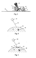
- FIG. 1 A first embodiment of a puncturing guide according to the present invention will be described in conjunction with Fig. 1 to Fig. 3 .
- Fig. 1 a puncturing guide 1 in a disassembled state.
- the puncturing guide 1 comprises basically a base plate 2, a tubular needle guide 3 and a retainer 4.
- the base plate 2 comprises a central, ring-shaped member 5 and flat legs 6, e.g. three, the undersides of which preferably are provided with a suitable adhesive for attachment to a patient's skin.
- a bore is formed, which extends from the top of the semi-sphere to bottom of the base plate 2.
- the outer radius of this first semi-sphere is the same as the inner radius of a second sliding surface in the form of a second segment 8 of second semi-sphere, which is provided on the shaft of the needle guide 3.
- the distance between the distal end of the needle guide 3 and the second segment 8 is equal to the outer radius of the first semi-sphere.
- the lower part of the retainer 4 is ring-shaped, while its upper part has been enlarged to a triangular shape, thereby providing a better grip for a user.
- the lower inside of the retainer 4 is chamfered (as is best seen in Fig.
- the upper inside of the hollow retainer 4 is also chamfered and narrows downwards to a diameter that is less than the diameter of the second segment 8.
- the retainer 4 is thereby provided with an internal waist.
- the outside of the lower ring-shaped part of the retainer 4 is provided with projections 9, which fit into grooves in the inside of the ring-shaped member 5, thereby providing a bayonet coupling between the base plate 2 and the retainer 4.
- Fig. 2 illustrates the puncturing guide 1 in an assembled state.
- the needle guide 3 is secured to the base plate 2 by the retainer 4, whose chamfered lower inside presses the inside of the second segment 8 (not visible in the figure) into contact with the first segment 7 (not visible in the figure).
- the distal end of the needle guide 3 is in level with the flat underside of the base plate 2.
- the center of the first semi-sphere constitutes the rotational center of the needle guide 3, and since the center of the first semi-sphere is located at the bottom of the base plate 2, the needle guide 3 rotates around a point located at the surface of an object, such as the skin of a patient, to which the base plate 2 of the puncturing guide 1 has been attached.
- a puncturing needle e.g. biopsy needle
- the retainer 4 does not fixedly lock the needle guide 3 to the base plate 2, i.e. the bayonet coupling is not fully tightened, so the second segment 8 can slide on the first segment 7.
- the cross-section of the puncturing guide 1 is shown in Fig. 3 .
- the projections 9 on the outside of the ring-shaped part of the retainer 4 are in engagement with corresponding grooves in the inside of the ring-shaped member 5, thereby providing a bayonet coupling between the retainer 4 and the base plate 2.
- the chamfered lower inside of the retainer 4 is in contact with the upper side of the second segment 8 and that the underside of the second segment 8 is in contact with the first segment 7.
- the second segment 8 can slide on the first segment 7, and the needle guide can be positioned in any angular direction within a certain angular interval, as will be explained below.
- the needle guide 3 When the bayonet coupling is tightened, the needle guide 3 is locked in a fixed position by the friction between the first segment 7 and the second segment 8 and by the friction between the second segment 8 and the chamfered inside of the retainer 4. Further, the special advantage of the puncturing guide 1 should also be recognized from Fig. 3 . Due to the fact that the second segment 8 slides on the first segment 7, the needle guide 3 rotates around the center point of the first semi-sphere, which in use is located at a patient's skin, so that the entrance point for the distal tip of a needle inserted in the needle guide 3 remains essentially the same irrespective of the angular orientation of the needle guide 3.
- the puncturing guide according to the present invention may be used in conjunction with a laser, or any suitable alignment equipment, to guide a puncturing needle into a target site within a patient's body
- a few remarks can be made regarding the puncturing guide 1 described with reference to Fig. 1 to Fig. 3 .
- the chamfering of the lower inside of the retainer 4 corresponds preferably to the outer radius of the second segment 8, thereby providing a secure locking for the needle guide 3 between the base plate 2 and the retainer 4.
- the needle guide 3 can assume any angular orientation within a certain angular interval. In particular from Fig.
- this angular interval is determined by the diameter of the bore through the first semi-sphere provided in the center of the ring-shaped member 5 as well as by the size of the second segment 8 provided on the shaft of the needle guide 3.
- the needle guide 3 is locked by means of a bayonet coupling between the base plate 2 and the retainer 4.
- attachment and retainer means could be used.
- the ring-shaped member and the retainer could be threaded into each other, or some kind of compressible or expandable clamping means could be used, or a screw could be provided that secures the retainer to the base plate and locks the needle guide in a fixed orientation.
- the part of the needle guide (3, 18) facing the defined puncturing entrance point is reinforced with reinforcement means having an essentially tubular shape.
- the reinforcement means is not shown in the figures. It is preferably an integral part of the needle guide.
- the reinforcement means serves two purposes. One is to strengthen the needle guide and the other is to make the needle guide visible on images obtained by e.g. X-ray or magnetic resonance techniques. If MRI is used the reinforcement means should preferably be made from a non-magnetic metal, e.g. non-magnetic stainless steel.
- a puncturing guide provided with a needle guide being movable around a point that coincides with the entrance point of a puncturing needle to be introduced into the body of a patient
- a puncturing guide according to the present invention can be used in any medical guiding procedure known in the state of the art.
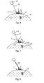
- Fig. 4 illustrates schematically a target site 10, such as an internal organ, embodied in surrounding tissue 11 under the skin 12 of a patient.
- the position of the target site 10 may have been determined by a CT scanner, which provides a doctor with image data from which the depth of the target site, the suitable puncturing point through the skin 12 as well as the suitable entrance angle for a puncturing needle can be determined.
- a laser beam 13 from a laser 14 indicates the entrance angle and the puncturing point at the skin 12.
- Fig. 5 illustrates schematically the first step of an alignment operation in which the puncturing guide 1 is employed.
- the center of the bore through the first semi-sphere on the base plate 2 is positioned so that the laser spot on the skin 12, which indicates the puncturing point, is in the center of the bore.
- the base plate 2 is secured in this position by means of the adhesive provided at the undersides of the flat legs 6.
- the base plate 2 could be attached to the patient's skin 12 by means of adhesive tape.
- the second step of the alignment operation is schematically illustrated in Fig. 6 .
- the needle guide 3 is placed on the base plate 2, with the second segment 8 resting on the first segment 7, and the ring-shaped part of the retainer 4 is positioned in the ring-shaped member 5.
- the bayonet coupling between the base plate 2 and the retainer 4 is not yet tightened, so the second segment 8 can slide on the first segment 7.
- the needle guide 3 is not aligned with the laser beam 13, but it should be noted that the distal end of the needle guide 3 is positioned at the puncturing point indicated by the laser spot on the skin 12 of the patient.
- Fig. 7 illustrates schematically the completion of the third step of the alignment operation, in which the second segment 8 of the needle guide 3 is slid on the first segment 7 such that the proximal end of the needle guide 3 is positioned in the laser beam 13, i.e. a laser spot is visible in the center of the proximal end of the needle guide 3.
- the retainer 4 is tightened, which secures the needle guide 3 in position.
- the special advantage of the puncturing guide 1 is seen. Since the needle guide 3 may be moved around the center of the first semi-sphere, which is located at skin 12, the entrance position does not change during this angular positioning of the needle guide 3. Consequently, when the third step has been completed, the needle guide 3 is aligned with the laser beam 13, with the needle guide 3 pointing at the puncturing point indicated by the laser spot on the skin 12.
- Fig. 8 is illustrated how a puncturing needle 15 is positioned inside the hollow needle guide 3
- Fig. 9 illustrates how the distal tip of the puncturing needle 15 is inserted into the target site 10, where a biopsy sample may be collected in a well known manner.
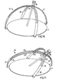
- Fig. 10 and Fig. 11 illustrate a second embodiment of a puncturing guide 16 in a first and second orientation, respectively.
- the puncturing guide 16 comprises basically a flat base plate 17, a tubular needle guide 18, a ring-shaped retainer 19, a first segment 20 of a first semi-sphere, and a second segment 21 of a second semi-sphere.
- the segments have the shapes of two semi-circular equally sized bows pivotally attached to the base plate 17 at positions separated by 90°, and that a slit is provided in each bow, wherein the needle guide 18 is adapted to be arranged in the slits at the intersection point of the bows wherein the needle guide 3, 18 is movable around a point that coincides with the defined puncturing entrance point.
- the distal end of the needle guide 18 is inserted in a bore in the center of the base plate 17.
- the inside of the ring-shaped retainer 19 is threaded and fits on a corresponding thread on the upper part of the needle guide 18.
- the needle guide 18 can slide inside the slits in the first and second segments 20, 21, with the distal tip of the needle guide being in contact, or almost in contact, with an object, such as the skin of a patient, beneath the base plate 17.
- the center of the first semi-sphere constitutes the rotational center of the needle guide 18, which means that a puncturing needle inserted into the needle guide 18 can be positioned in different angular orientations without changing the entrance point through a patient's skin for the distal tip of this puncturing needle.
- the reference numerals 22, 23 refer to two bow-shaped members between which the slit in the first segment 20 is provided (and the reference numerals 24, 25 refer to corresponding members of the second segment 21).
- the members 22, 23 (and the members 24, 25) can be detachable attached to each other by means of, for example, screws 26, so that the first and second segments 20, 21 can be removed from the puncturing guide 16.
- this feature may be advantageous if a doctor, in a final stage of the insertion procedure, wants to manipulate a puncturing needle without any assistance from a puncturing guide.
Landscapes
- Health & Medical Sciences (AREA)
- Surgery (AREA)
- Life Sciences & Earth Sciences (AREA)
- Medical Informatics (AREA)
- Nuclear Medicine, Radiotherapy & Molecular Imaging (AREA)
- Engineering & Computer Science (AREA)
- Biomedical Technology (AREA)
- Heart & Thoracic Surgery (AREA)
- Pathology (AREA)
- Molecular Biology (AREA)
- Animal Behavior & Ethology (AREA)
- General Health & Medical Sciences (AREA)
- Public Health (AREA)
- Veterinary Medicine (AREA)
- Infusion, Injection, And Reservoir Apparatuses (AREA)
- External Artificial Organs (AREA)
Claims (17)
- Punktionsführung (1) zum Führen einer Punktionsnadel in eine Zielstelle im Körper eines Patienten, die eine Grundplatte (2), die an einem vorgegebenen Einstichpunkt am Körper des Patienten positioniert wird, eine Nadelführung (3) zum Führen der Punktionsnadel bei der Einführung und einen Halter (4) zum Fixieren der Nadelführung (3) in einer fixen Position relativ zur Grundplatte (2) umfasst, worin die Grundplatte (2) ein erstes Segment (7) aufweist, das in Gleitkontakt mit einem zweiten Segment (8) steht, das an der Nadelführung (3) befestigt ist, dadurch gekennzeichnet, dass das erste Segment (7) im Wesentlichen die Form einer Halbkugel mit einer Mitte auf derselben Höhe wie die Unterseite der Grundplatte (2) aufweist, worin die Mitte mit dem Punkt zusammenfällt, der mit dem vorgegebenen Einstichpunkt zusammenfällt, und dass das zweite Segment (8) im Wesentlichen die Form einer zweiten Halbkugel mit einer Mitte aufweist, die mit der Mitte der ersten Halbkugel zusammenfällt, und dass der Halter (4) über dem zweiten Segment (8) angeordnet werden kann und eine Durchgangsöffnung aufweist, worin bei Zusammenwirken der ersten und zweiten Segmente (7, 8), wenn der Halter über dem zweiten Segment angeordnet ist, die Nadelführung (3) um einen Punkt bewegt werden kann, der mit der vorgegebenen Einstichöffnung zusammenfällt.
- Punktionsführung (1) nach Anspruch 1, dadurch gekennzeichnet, dass die Grundplatte (2) mit einem zentralen ringförmigen Element (5) versehen ist, in dessen Mitte das erste Segment (7) vorgesehen ist, und dass das zweite Segment (8) auf dem Schaft der Nadelführung (3) vorgesehen ist, worin das erste Segment (7) ein Bohrloch aufweist, das sich durch die Halbkugel des ersten Segments und die Grundplatte (2) erstreckt.
- Punktionsführung (1) nach Anspruch 2, dadurch gekennzeichnet, dass der Halter (4) eine Durchgangsöffnung aufweist, wobei die Öffnung einen oberen Teil, an dem die Öffnung abwärts bis zu einer Größe verengt ist, die kleiner ist als die Breite des zweiten Segments (8) in einer Ebene lotrecht zur Hauptachse der Nadelführung (3), und einen unteren ringförmigen Teil aufweist, der mit Befestigungsmitteln versehen ist, die entsprechenden Befestigungsmitteln auf dem ringförmigen Element (5) auf der Grundplatte entsprechen, um die Nadelführung (3) an der Grundplatte (2) zu fixieren.
- Punktionsführung (1) nach Anspruch 3, dadurch gekennzeichnet, dass die Innenseite des unteren ringförmigen Teils des Halters (4) eine Form aufweist, die der Form des zweiten Segments (8) entspricht.
- Punktionsführung (1) nach Anspruch 4, dadurch gekennzeichnet, dass die Form der Innenseite des unteren ringförmigen Teils des Halters (4) abgeschrägt ist, wobei die Abschrägung der Form des zweiten Segments (8) entspricht.
- Punktionsführung (1) nach einem der Ansprüche 3-5, dadurch gekennzeichnet, dass die Außenseite des oberen Teils des Halters (4) vergrößert ist, um einen Griff für den Anwender zu bilden.
- Punktionsführung (1) nach Anspruch 1, dadurch gekennzeichnet, dass die Grundplatte (2) mit einer Anzahl flacher Beine (6) zur Befestigung an der Haut des Patienten versehen ist.
- Punktionsführung (1) nach Anspruch 7, dadurch gekennzeichnet, dass die Unterseiten der flachen Beine mit einem geeigneten Kleber versehen sind, damit sie auf der Haut des Patienten befestigt werden können.
- Punktionsführung (1) nach einem der Ansprüche 3-8, dadurch gekennzeichnet, dass die Außenseite des unteren ringförmigen Teils des Halters (4) mit Vorsprüngen (9) versehen ist, die in Nuten im ringförmigen Element (5) passen, wodurch eine Bajonettkupplung zwischen der Grundplatte (2) und der Nadelführung (3) bereitgestellt wird.
- Punktionsführung (1) nach einem der Ansprüche 3-9, dadurch gekennzeichnet, dass der Teil der Nadelführung (3, 18), der zum vorgegebenen Einstichpunkt weist, mit einem Verstärkungsmittel von im Wesentlichen röhrenförmiger Gestalt verstärkt ist.
- Punktionsführung (1) nach Anspruch 10, dadurch gekennzeichnet, dass das Verstärkungsmittel ein integraler Bestandteil der Nadelführung ist.
- Punktionsführung (1) nach Anspruch 10 oder 11, dadurch gekennzeichnet, dass das Verstärkungsmittel aus einem Material, z.B. einem Metall, besteht, das es auf Röntgenbildern sichtbar macht.
- Punktionsführung (1) nach Anspruch 12, dadurch gekennzeichnet, dass das Verstärkungsmittel aus einem Material, z.B. nichtmagnetischem Edelstahl, besteht, das es für Magnetresonanztomographie kompatibel macht.
- Punktionsnadel (16) zum Führen einer Punktionsnadel in eine Zielstelle im Körper eines Patienten, die eine Grundplatte (17), die an einem vorgegebenen Einstichpunkt am Körper des Patienten positioniert wird, eine Nadelführung (18) zum Führen der Punktionsnadel bei der Einführung und einen Halter (19) zum Fixieren der Nadelführung (18) in einer fixen Position relativ zur Grundplatte (17) umfasst, worin die Grundplatte (17) ein erstes Segment (20) aufweist, das in Gleitkontakt mit einem zweiten Segment (21) steht, das an der Nadelführung (18) befestigt ist, dadurch gekennzeichnet, dass das erste Segment (20) und das zweite Segment (21) die Form von zwei halbkreisförmigen, gleich großen Bögen aufweisen, die an Stellen, die um 90° voneinander getrennt sind, gelenkig an der Grundplatte (17) befestigt sind, und dass ein Schlitz in jedem Bogen vorgesehen ist, worin die Nadelführung (18) in den Schlitzen am Schnittpunkt der Bögen angeordnet werden kann, worin bei Zusammenwirken der ersten und zweiten Segmente (20, 21), wenn der Halter über dem zweiten Segment angeordnet ist, die Nadelführung (18) um einen Punkt bewegt werden kann, der mit der vorgegebenen Einstichöffnung zusammenfällt.
- Punktionsführung (16) nach Anspruch 14, dadurch gekennzeichnet, dass die Innenseite des Halters (19) mit einem Gewinde versehen ist und auf ein entsprechendes Gewinde auf der Außenseite der Nadelführung (18) passt, so dass die Nadelführung (18) in einer Position fixiert werden kann, indem der Halter (19) auf der Nadelführung (18) angezogen wird, wobei di ersten und zweiten Segmente (20, 21) dazwischen angeordnet sind.
- Verfahren zur Positionierung einer Punktionsführung (1, 16) nach einem der Ansprüche 1 bis 15 an einem Einstichpunkt auf der Haut eines Patienten,
dadurch gekennzeichnet, dass das Verfahren folgende Schritte umfasst:(a) Positionierung der Grundplatte (2, 17) auf der Haut des Patienten, so dass der Einstichpunkt über ein Loch in der Grundplatte erreicht werden kann;(b) Platzierung der Nadelführung (3, 18) auf der Grundplatte (2, 17), so dass das zweite Segment (8, 21) auf dem ersten Segment (7, 20) gleiten kann, wobei das distale Ende der Nadelführung (3, 18) mit dem Einstichpunkt durch das Loch in der Grundplatte (2, 17) in Berührung steht;(c) Bewegung der Nadelführung (3, 18) in eine solche Position, dass eine Zielstelle im Patienten erreicht werden kann; und(d) Fixierung der Nadelführung (3, 18) an der Grundplatte (2, 17) mit Hilfe des Halters (4, 19). - Verfahren nach Anspruch 16, dadurch gekennzeichnet, dass die Positionierung der Punktionsführung mit Hilfe eines Laserstrahls (13) erfolgt, der den Einstichpunkt auf der Haut des Patienten und den Eintrittswinkel durch den Einstichpunkt anzeigt, dass die Grundplatte (2, 17) auf der Haut des Patienten positioniert ist, so dass die Laserstrahlanzeige in das Loch der Grundplatte fällt, und dass die Nadelführung (3, 18) so bewegt wird, dass der Laserstrahl sich am proximalen Ende der Nadelführung (3, 18) befindet.
Applications Claiming Priority (5)
| Application Number | Priority Date | Filing Date | Title |
|---|---|---|---|
| US40795902P | 2002-09-05 | 2002-09-05 | |
| SE0202633 | 2002-09-05 | ||
| SE0202633A SE524042C2 (sv) | 2002-09-05 | 2002-09-05 | Punktionsguide för styrning av en punktionsnål till ett målställe i en patients kropp |
| US407959P | 2002-09-05 | ||
| PCT/SE2003/001349 WO2004021898A1 (en) | 2002-09-05 | 2003-09-01 | Guide for a medical device |
Publications (2)
| Publication Number | Publication Date |
|---|---|
| EP1534153A1 EP1534153A1 (de) | 2005-06-01 |
| EP1534153B1 true EP1534153B1 (de) | 2009-04-15 |
Family
ID=31980724
Family Applications (1)
| Application Number | Title | Priority Date | Filing Date |
|---|---|---|---|
| EP03794385A Expired - Lifetime EP1534153B1 (de) | 2002-09-05 | 2003-09-01 | Führung für eine medizinische vorrichtung |
Country Status (7)
| Country | Link |
|---|---|
| US (1) | US7824417B2 (de) |
| EP (1) | EP1534153B1 (de) |
| JP (1) | JP4382667B2 (de) |
| AT (1) | ATE428360T1 (de) |
| AU (1) | AU2003256201B2 (de) |
| DE (1) | DE60327213D1 (de) |
| WO (1) | WO2004021898A1 (de) |
Cited By (2)
| Publication number | Priority date | Publication date | Assignee | Title |
|---|---|---|---|---|
| US8401620B2 (en) | 2006-10-16 | 2013-03-19 | Perfint Healthcare Private Limited | Needle positioning apparatus and method |
| US8613748B2 (en) | 2010-11-10 | 2013-12-24 | Perfint Healthcare Private Limited | Apparatus and method for stabilizing a needle |
Families Citing this family (122)
| Publication number | Priority date | Publication date | Assignee | Title |
|---|---|---|---|---|
| US7662161B2 (en) | 1999-09-13 | 2010-02-16 | Rex Medical, L.P | Vascular hole closure device |
| US7452357B2 (en) | 2004-10-22 | 2008-11-18 | Ethicon Endo-Surgery, Inc. | System and method for planning treatment of tissue |
| US7833221B2 (en) | 2004-10-22 | 2010-11-16 | Ethicon Endo-Surgery, Inc. | System and method for treatment of tissue using the tissue as a fiducial |
| GB0505782D0 (en) * | 2005-03-22 | 2005-04-27 | Depuy Int Ltd | Surgical guide |
| US20080015639A1 (en) * | 2006-01-19 | 2008-01-17 | Bjork Todd M | Anchorless non-invasive force dissipation system for orthopedic instrumentation |
| WO2008047379A2 (en) * | 2006-03-07 | 2008-04-24 | Hirdesh Sahni | An image guided whole body stereotactic needle placement device |
| US8308740B2 (en) * | 2006-06-05 | 2012-11-13 | Kristin Ann Tolley | Needle stabilizer |
| EP1958588A3 (de) | 2007-02-19 | 2010-09-22 | Radi Medical Devices AB | Medizinische Vorrichtung zur Führung eines medizinischen Instruments |
| US10335236B1 (en) | 2007-11-01 | 2019-07-02 | Stephen B. Murphy | Surgical system using a registration device |
| US11992271B2 (en) | 2007-11-01 | 2024-05-28 | Stephen B. Murphy | Surgical system using a registration device |
| US9101431B2 (en) | 2007-11-01 | 2015-08-11 | Stephen B. Murphy | Guide for acetabular component positioning |
| US8267938B2 (en) | 2007-11-01 | 2012-09-18 | Murphy Stephen B | Method and apparatus for determining acetabular component positioning |
| US8986309B1 (en) | 2007-11-01 | 2015-03-24 | Stephen B. Murphy | Acetabular template component and method of using same during hip arthrosplasty |
| US8491629B2 (en) | 2008-02-15 | 2013-07-23 | Rex Medical | Vascular hole closure delivery device |
| US8920462B2 (en) * | 2008-02-15 | 2014-12-30 | Rex Medical, L.P. | Vascular hole closure device |
| US8070772B2 (en) | 2008-02-15 | 2011-12-06 | Rex Medical, L.P. | Vascular hole closure device |
| US9226738B2 (en) | 2008-02-15 | 2016-01-05 | Rex Medical, L.P. | Vascular hole closure delivery device |
| US20110029013A1 (en) | 2008-02-15 | 2011-02-03 | Mcguckin James F | Vascular Hole Closure Device |
| US8920463B2 (en) | 2008-02-15 | 2014-12-30 | Rex Medical, L.P. | Vascular hole closure device |
| US8232890B2 (en) * | 2008-07-18 | 2012-07-31 | The Board Of Regents Of The University Of Texas System | Guidance system and method for medical procedures |
| DE202009018442U1 (de) | 2008-07-22 | 2011-09-28 | Johnson Electric Dresden Gmbh | Positioniervorrichtung für labor- und medizintechnische Geräte |
| US10863970B2 (en) | 2008-12-18 | 2020-12-15 | C. R. Bard, Inc. | Needle guide including enhanced visibility entrance |
| WO2010080637A1 (en) | 2008-12-18 | 2010-07-15 | C. R. Bard, Inc. | Needle guides for a sonographic imaging device |
| GB2467139A (en) | 2009-01-22 | 2010-07-28 | Neorad As | Needle Holder |
| US9232977B1 (en) * | 2009-03-27 | 2016-01-12 | Tausif-Ur Rehman | Instrument guiding device |
| USD618796S1 (en) * | 2009-07-28 | 2010-06-29 | Vertos Medical, Inc. | Lockable articulating base plate |
| US20120053573A1 (en) * | 2010-08-31 | 2012-03-01 | Elekta Limited | Surgical Apparatus |
| US8788046B2 (en) | 2010-11-11 | 2014-07-22 | Spr Therapeutics, Llc | Systems and methods for the treatment of pain through neural fiber stimulation |
| US8788048B2 (en) | 2010-11-11 | 2014-07-22 | Spr Therapeutics, Llc | Systems and methods for the treatment of pain through neural fiber stimulation |
| US8788047B2 (en) | 2010-11-11 | 2014-07-22 | Spr Therapeutics, Llc | Systems and methods for the treatment of pain through neural fiber stimulation |
| US9974516B2 (en) | 2010-12-22 | 2018-05-22 | C. R. Bard, Inc. | Selectable angle needle guide |
| GB2489492B (en) * | 2011-03-31 | 2017-09-06 | Surgical Innovations Ltd | Surgical positioning assembly and surgical instrument |
| KR20140040827A (ko) | 2011-06-23 | 2014-04-03 | 씨. 알. 바드, 인크. | 선택가능한 애스펙트를 가지는 바늘 안내부 |
| EP2779924B1 (de) | 2011-08-22 | 2020-01-01 | Visualase, Inc. | Stereotaktische zugangsvorrichtungen |
| US9387008B2 (en) | 2011-09-08 | 2016-07-12 | Stryker European Holdings I, Llc | Axial surgical trajectory guide, and method of guiding a medical device |
| DE102011085308A1 (de) | 2011-10-27 | 2013-05-02 | Siemens Aktiengesellschaft | Verfahren zur Unterstützung einer einen minimalinvasiven Eingriff durchführenden Person und Magnetresonanzeinrichtung |
| KR101876386B1 (ko) * | 2011-12-29 | 2018-07-11 | 삼성전자주식회사 | 의료용 로봇 시스템 및 그 제어 방법 |
| US9498297B2 (en) * | 2012-04-18 | 2016-11-22 | United Arab Emirates University | Manipulator for surgical tools |
| US9199044B2 (en) * | 2012-08-06 | 2015-12-01 | Elwha Llc | Devices and methods for wearable injection guides |
| US20140276559A1 (en) * | 2013-03-12 | 2014-09-18 | Christopher Page | Devices, systems and methods for placement of instruments for medical procedures |
| US9222996B2 (en) * | 2013-03-15 | 2015-12-29 | The Brigham And Women's Hospital, Inc. | Needle placement manipulator with two rotary guides |
| US10274553B2 (en) | 2013-03-15 | 2019-04-30 | Canon U.S.A., Inc. | Needle placement manipulator with attachment for RF-coil |
| JP6193111B2 (ja) * | 2013-12-13 | 2017-09-06 | テルモ株式会社 | 医療用器具 |
| US9901400B2 (en) * | 2014-01-23 | 2018-02-27 | Visualise, Inc. | Stereotactic access devices and methods |
| USD874648S1 (en) | 2014-01-26 | 2020-02-04 | Visualase, Inc. | Access device |
| JP6467434B2 (ja) | 2014-02-27 | 2019-02-13 | ザ ブリガム アンド ウィメンズ ホスピタル インコーポレイテッドThe Brigham and Women’s Hospital, Inc. | 載置装置 |
| WO2015138883A1 (en) * | 2014-03-13 | 2015-09-17 | New York University | Position guidance device with bubble level |
| WO2015171988A1 (en) | 2014-05-09 | 2015-11-12 | Canon U.S.A., Inc. | Positioning apparatus |
| JP6400682B2 (ja) * | 2014-07-15 | 2018-10-03 | テレフレックス メディカル インコーポレイテッド | 交換式外科用アクセスポート組立体 |
| US9924979B2 (en) * | 2014-09-09 | 2018-03-27 | Medos International Sarl | Proximal-end securement of a minimally invasive working channel |
| US10111712B2 (en) | 2014-09-09 | 2018-10-30 | Medos International Sarl | Proximal-end securement of a minimally invasive working channel |
| US10264959B2 (en) | 2014-09-09 | 2019-04-23 | Medos International Sarl | Proximal-end securement of a minimally invasive working channel |
| WO2016040817A1 (en) | 2014-09-12 | 2016-03-17 | Canon U.S.A., Inc. | Needle positioning apparatus |
| WO2016118706A1 (en) * | 2015-01-22 | 2016-07-28 | Krimsky William Sanford | Device for medical procedure localization and/or insertion |
| WO2016069364A1 (en) * | 2014-10-28 | 2016-05-06 | Cogentix Medical, Inc. | Method and device for controlled delivery of medical devices |
| JP6625655B2 (ja) * | 2014-11-18 | 2019-12-25 | メドス・インターナショナル・エスエイアールエルMedos International SARL | 最小侵襲性作業通路の近位端の固定 |
| CN104490464B (zh) * | 2014-12-15 | 2017-05-03 | 赵继军 | 开放手术椎弓根导向器 |
| CN104490465B (zh) * | 2014-12-15 | 2017-04-12 | 田勇 | 股骨颈导向器 |
| TWM503196U (zh) * | 2015-01-14 | 2015-06-21 | Reference Technology Ltd Company | 立體定位穩定器 |
| EP3058890B1 (de) * | 2015-02-18 | 2017-10-04 | Medizinische Hochschule Hannover | Chirurgische Führungsvorrichtung und Verfahren zu ihrer Herstellung |
| US10925633B2 (en) | 2015-05-15 | 2021-02-23 | The Research Foundation For The State University Of New York | Needle guide device and method |
| US9867673B2 (en) | 2015-07-14 | 2018-01-16 | Canon U.S.A, Inc. | Medical support device |
| CN104958099B (zh) * | 2015-07-15 | 2017-04-05 | 江苏舟可医疗器械科技有限公司 | 3d打印椎间孔镜靶向穿刺经皮手术导板及其穿刺方法 |
| US10639065B2 (en) | 2015-07-21 | 2020-05-05 | Canon U.S.A., Inc. | Medical assist device |
| CA3002033A1 (en) * | 2015-10-15 | 2017-04-20 | Spr Therapeutics, Llc | Apparatus and method for positioning, implanting and using a stimulation lead |
| US11135437B2 (en) | 2015-10-15 | 2021-10-05 | Spr Therapeutics, Inc. | Apparatus and method for positioning, implanting and using a stimulation lead |
| US11413450B2 (en) | 2015-10-15 | 2022-08-16 | Spr Therapeutics, Inc. | Apparatus and method for positioning, implanting and using a stimulation lead |
| JP6952696B2 (ja) * | 2015-12-16 | 2021-10-20 | キヤノン ユーエスエイ, インコーポレイテッドCanon U.S.A., Inc | 医療ガイダンス装置 |
| WO2017120434A2 (en) * | 2016-01-08 | 2017-07-13 | Boston Scientific Scimed, Inc., | Devices and methods for guiding a surgical instrument |
| WO2017132505A1 (en) | 2016-01-29 | 2017-08-03 | Canon U.S.A., Inc. | Tool placement manipulator |
| WO2017180950A1 (en) | 2016-04-15 | 2017-10-19 | Stryker European Holdings I, Llc | Cannula lock with a brake that rotates and anchors that deploy into the bone against which the cannula lock is set |
| CN105852967A (zh) * | 2016-04-21 | 2016-08-17 | 南京鼓楼医院 | 3d打印经皮穿刺胸腰椎及周围组织脏器导航器及其导航方法 |
| WO2018049078A1 (en) | 2016-09-07 | 2018-03-15 | Vertos Medical, Inc. | Percutaneous lateral recess resection methods and instruments |
| US10933223B2 (en) | 2016-09-30 | 2021-03-02 | Boston Scientific Scimed, Inc. | Access devices and associated methods |
| JP6948389B2 (ja) | 2016-10-19 | 2021-10-13 | キヤノン ユーエスエイ, インコーポレイテッドCanon U.S.A., Inc | 穿刺器具を位置決めするための配置マニピュレータおよびアタッチメント |
| US11540973B2 (en) | 2016-10-21 | 2023-01-03 | Spr Therapeutics, Llc | Method and system of mechanical nerve stimulation for pain relief |
| US10610325B2 (en) | 2017-02-16 | 2020-04-07 | Canon U.S.A., Inc. | Medical guidance apparatus |
| CN110621244B (zh) * | 2017-05-23 | 2023-02-21 | 波士顿科学有限公司 | 外科手术引导系统、装置和方法 |
| US10675099B2 (en) | 2017-09-22 | 2020-06-09 | Canon U.S.A., Inc. | Needle insertion guide device and system, and method of providing control guidance for needle insertion guide device |
| US11197723B2 (en) | 2017-10-09 | 2021-12-14 | Canon U.S.A., Inc. | Medical guidance system and method using localized insertion plane |
| FR3073135B1 (fr) * | 2017-11-09 | 2019-11-15 | Quantum Surgical | Dispositif robotise pour une intervention medicale mini-invasive sur des tissus mous |
| CN107898490B (zh) * | 2017-12-07 | 2024-05-28 | 无锡圣诺亚科技有限公司 | 万向穿刺定位器 |
| ES2976202T3 (es) | 2018-01-10 | 2024-07-26 | The Provost Fellows Scholars And Other Members Of Board Of Trinity College Dublin | Sistema para sellar un canal en tejido |
| JP6434665B1 (ja) * | 2018-02-19 | 2018-12-05 | 清 ▲高▼木 | 頭部手術補助器具 |
| US11213315B2 (en) | 2018-03-16 | 2022-01-04 | Canon U.S.A., Inc. | Method and apparatus for a medical guidance device |
| US11109933B2 (en) | 2018-03-29 | 2021-09-07 | Melissa Seely-Morgan | Devices for supporting a medical instrument and methods of use |
| CN108597338B (zh) * | 2018-05-30 | 2024-05-31 | 宁波市第六医院 | 经皮椎体后凸成形术教学模型精确角度穿刺辅助装置及其使用方法 |
| US11617621B2 (en) | 2018-08-03 | 2023-04-04 | Canon U.S.A., Inc. | System and method for multi-probe guidance |
| JP6962976B2 (ja) | 2018-08-15 | 2021-11-05 | キヤノン ユーエスエイ, インコーポレイテッドCanon U.S.A., Inc | 医療用ツールガイダンス装置 |
| US11504105B2 (en) | 2019-01-25 | 2022-11-22 | Rex Medical L.P. | Vascular hole closure device |
| CN109620399A (zh) * | 2019-02-18 | 2019-04-16 | 大连医科大学附属第医院 | 一种用于颈2背根神经节射频的穿刺定位装置及利用其穿刺定位的方法 |
| CN109893222B (zh) * | 2019-02-28 | 2024-02-13 | 成都真实维度科技有限公司 | 一种用于介入消融的植入性治疗激光定位的穿刺引导器 |
| CN109938796A (zh) * | 2019-04-18 | 2019-06-28 | 上理检测技术(上海)有限公司 | 局部压迫止血装置 |
| CN110051403A (zh) * | 2019-04-18 | 2019-07-26 | 上理检测技术(上海)有限公司 | 局部压迫止血装置 |
| CN110037781B (zh) * | 2019-05-27 | 2024-06-07 | 广东工业大学 | 一种穿刺辅助导向装置 |
| CN110236656A (zh) * | 2019-07-22 | 2019-09-17 | 李禄鑫 | 一种可辅助同轴套管针调整角度的固定装置 |
| CN110279456B (zh) * | 2019-07-25 | 2024-04-12 | 娄底市中心医院 | 一种应用于椎间孔镜手术的穿刺定位导向器及其使用方法 |
| CN110720971B (zh) * | 2019-11-15 | 2024-07-23 | 福建骏格科技有限公司 | 一种穿刺固定支架 |
| KR102457453B1 (ko) * | 2020-04-28 | 2022-10-24 | (의료)길의료재단 | 천자용 니들 홀더 |
| CN112006774B (zh) * | 2020-07-28 | 2024-09-20 | 常州锦瑟医疗信息科技有限公司 | 手术定位装置 |
| CN111904622A (zh) * | 2020-07-31 | 2020-11-10 | 青岛市中心医院 | 一种乳腺肿瘤定位装置 |
| US20220039900A1 (en) * | 2020-08-06 | 2022-02-10 | Canon U.S.A., Inc. | Used device detection |
| US12383246B2 (en) | 2020-10-12 | 2025-08-12 | Abbott Cardiovascular Systems, Inc. | Vessel closure device with improved safety and tract hemostasis |
| CN112155692A (zh) * | 2020-10-26 | 2021-01-01 | 任莉霞 | 一种心血管内科临床穿刺装置 |
| CN112263350A (zh) * | 2020-11-10 | 2021-01-26 | 南华大学附属南华医院 | 一种大鼠颅脑三维定位穿刺装置 |
| EP4029462B1 (de) | 2021-01-19 | 2023-12-06 | Imactis | Ständer für eine punktionsvorrichtung |
| CN112842487B (zh) * | 2021-02-06 | 2021-12-14 | 中南大学湘雅医院 | 一种胰腺穿刺定位器 |
| CN114391927B (zh) * | 2021-04-22 | 2024-02-23 | 徐明荣 | 一种ct引导穿刺定位导向装置及其方法 |
| CN113397661B (zh) * | 2021-06-02 | 2022-06-10 | 河北医科大学第二医院 | 一种腹腔穿刺定位导航系统 |
| CN113349904B (zh) * | 2021-07-15 | 2022-11-22 | 重庆大学附属肿瘤医院 | 一种胸腔肺部穿刺针固定装置 |
| CN113679453B (zh) * | 2021-08-14 | 2023-05-30 | 河南省人民医院 | 一种多角度可调式肝胆外科手术穿刺装置 |
| CN113827320B (zh) * | 2021-09-23 | 2023-06-09 | 中南大学湘雅医院 | 一种穿刺深度可调的穿刺器 |
| CN114404000B (zh) * | 2022-02-17 | 2023-09-08 | 青岛市妇女儿童医院(青岛市妇幼保健院、青岛市残疾儿童医疗康复中心、青岛市新生儿疾病筛查中心) | 一种便于使用的妇产科麻醉穿刺点防护罩 |
| CN115005944B (zh) * | 2022-06-06 | 2024-11-15 | 中山大学肿瘤防治中心(中山大学附属肿瘤医院、中山大学肿瘤研究所) | 一种穿刺针引导装置 |
| JP2025520556A (ja) | 2022-06-16 | 2025-07-03 | ヴェルトス・メディカル,インコーポレイテッド | 一体型器具アセンブリ |
| CN115708710A (zh) * | 2022-10-28 | 2023-02-24 | 苏州派尼迩医疗科技有限公司 | 用于穿刺机器人穿刺定位的定位件、定位装置及定位方法 |
| CN115998389B (zh) * | 2023-03-24 | 2023-07-28 | 浙江伽奈维医疗科技有限公司 | 一种手术机器人的复合引导前端装置及定位方法 |
| CN116035669B (zh) * | 2023-03-28 | 2023-10-27 | 真健康(北京)医疗科技有限公司 | 电磁驱动的两自由度穿刺针导向装置 |
| CN117137596B (zh) * | 2023-10-30 | 2024-01-12 | 湖南明舟医疗科技有限公司 | 穿刺针组件及一次性穿刺针 |
| CN118415748B (zh) * | 2024-04-22 | 2024-11-29 | 中国人民解放军东部战区总医院 | 一种用于肝癌微波消融的多点穿刺定位器 |
| CN118593084B (zh) * | 2024-06-30 | 2024-12-24 | 扬州大学附属医院(扬州市第一人民医院) | 一种肾脏活检穿刺取样装置 |
| CN119280502B (zh) * | 2024-10-18 | 2026-04-03 | 复旦大学附属中山医院 | 一种穿刺器 |
Family Cites Families (20)
| Publication number | Priority date | Publication date | Assignee | Title |
|---|---|---|---|---|
| US2697433A (en) * | 1951-12-04 | 1954-12-21 | Max A Zehnder | Device for accurately positioning and guiding guide wires used in the nailing of thefemoral neck |
| US3021842A (en) | 1958-11-05 | 1962-02-20 | John F Flood | Hypodermic needle guide |
| CH444683A (de) * | 1963-12-20 | 1967-09-30 | Bofors Ab | Steuergerät mit zwei Freiheitsgraden mit einem in einem Universalgelenk gelagerten Steuerhebel |
| US4608977A (en) * | 1979-08-29 | 1986-09-02 | Brown Russell A | System using computed tomography as for selective body treatment |
| US4805615A (en) * | 1985-07-02 | 1989-02-21 | Carol Mark P | Method and apparatus for performing stereotactic surgery |
| US4733661A (en) | 1987-04-27 | 1988-03-29 | Palestrant Aubrey M | Guidance device for C.T. guided drainage and biopsy procedures |
| FR2626773A1 (fr) * | 1988-02-05 | 1989-08-11 | Puy Philippe | Support de sonde echographique, notamment de sonde echocardiographique |
| US5201742A (en) * | 1991-04-16 | 1993-04-13 | Hasson Harrith M | Support jig for a surgical instrument |
| US5263956A (en) | 1992-03-04 | 1993-11-23 | Neuro Navigational Corporation | Ball joint for neurosurgery |
| US5767839A (en) * | 1995-01-18 | 1998-06-16 | Immersion Human Interface Corporation | Method and apparatus for providing passive force feedback to human-computer interface systems |
| US5643286A (en) * | 1994-06-24 | 1997-07-01 | Cytotherapeutics, Inc. | Microdrive for use in stereotactic surgery |
| JP3111036B2 (ja) | 1997-03-11 | 2000-11-20 | アロカ株式会社 | 超音波探触子 |
| JP2002502328A (ja) * | 1997-05-28 | 2002-01-22 | ステファン・ビー・オーガー | 木材および他の支持体用の鉱物性染料 |
| DE19808220B4 (de) | 1997-06-19 | 2007-11-29 | Mri Devices Daum Gmbh | Nadeltrokar |
| DE19726141A1 (de) * | 1997-06-19 | 1999-01-28 | Daum Gmbh | Neurotrokar |
| US6289263B1 (en) * | 1997-12-16 | 2001-09-11 | Board Of Trustees Operating Michigan State University | Spherical mobile robot |
| US6110182A (en) * | 1998-06-22 | 2000-08-29 | Ohio Medical Instruments Company, Inc. | Target socket |
| JP2001128974A (ja) | 1999-11-08 | 2001-05-15 | Toshiba Corp | 超音波診断装置用の穿刺アダプタ及び超音波診断装置 |
| AU2001285071A1 (en) * | 2000-08-17 | 2002-02-25 | John David | Trajectory guide with instrument immobilizer |
| DE10055293A1 (de) * | 2000-11-03 | 2002-05-29 | Storz Karl Gmbh & Co Kg | Vorrichtung zum Halten und Positionieren eines endoskopischen Instruments |
-
2003
- 2003-09-01 AU AU2003256201A patent/AU2003256201B2/en not_active Expired
- 2003-09-01 EP EP03794385A patent/EP1534153B1/de not_active Expired - Lifetime
- 2003-09-01 US US10/494,255 patent/US7824417B2/en active Active
- 2003-09-01 DE DE60327213T patent/DE60327213D1/de not_active Expired - Lifetime
- 2003-09-01 AT AT03794385T patent/ATE428360T1/de not_active IP Right Cessation
- 2003-09-01 JP JP2004533929A patent/JP4382667B2/ja not_active Expired - Lifetime
- 2003-09-01 WO PCT/SE2003/001349 patent/WO2004021898A1/en not_active Ceased
Cited By (3)
| Publication number | Priority date | Publication date | Assignee | Title |
|---|---|---|---|---|
| US8401620B2 (en) | 2006-10-16 | 2013-03-19 | Perfint Healthcare Private Limited | Needle positioning apparatus and method |
| US8774901B2 (en) | 2006-10-16 | 2014-07-08 | Perfint Healthcare Private Limited | Needle positioning apparatus and method |
| US8613748B2 (en) | 2010-11-10 | 2013-12-24 | Perfint Healthcare Private Limited | Apparatus and method for stabilizing a needle |
Also Published As
| Publication number | Publication date |
|---|---|
| AU2003256201B2 (en) | 2006-06-01 |
| WO2004021898A1 (en) | 2004-03-18 |
| ATE428360T1 (de) | 2009-05-15 |
| EP1534153A1 (de) | 2005-06-01 |
| JP2005537850A (ja) | 2005-12-15 |
| US7824417B2 (en) | 2010-11-02 |
| JP4382667B2 (ja) | 2009-12-16 |
| DE60327213D1 (de) | 2009-05-28 |
| US20040260312A1 (en) | 2004-12-23 |
| AU2003256201A1 (en) | 2004-03-29 |
Similar Documents
| Publication | Publication Date | Title |
|---|---|---|
| US7824417B2 (en) | Guide for a medical device | |
| US20240423748A1 (en) | Surgical Head Clamp and Robotics Platform | |
| US7658879B2 (en) | Trajectory guide with angled or patterned guide lumens or height adjustment | |
| US6368330B1 (en) | Apparatus for frameless stereotactic surgery | |
| EP0904741B1 (de) | Vorrichtung zur Halterung eines chirurgischen Instrumentes | |
| US9125676B2 (en) | Image guided whole body stereotactic needle placement device with falling arc | |
| US9408627B2 (en) | Image guided whole body stereotactic needle placement device | |
| US8192445B2 (en) | Trajectory guide with instrument immobilizer | |
| CA2303335C (en) | Device and method for setting stereotactic and endoscopically placed equipment | |
| US20070149878A1 (en) | Apparatus and method for guiding a medical device in multiple planes | |
| JP2021072929A (ja) | 手術器具を案内するための装置及び方法 | |
| US20050033315A1 (en) | Apparatus and method for guiding a medical device | |
| CN102123677A (zh) | 轨迹引导装置 | |
| US10398526B2 (en) | Assembly for positioning electrodes for radiofrequency tissue ablation | |
| US10265136B2 (en) | Cranial anchoring and positioning system and method | |
| EP0979637B1 (de) | Gerät zum Führen einer Punktionsnadel | |
| EP3397167B1 (de) | Vorrichtung zur interventionellen akustischen bildgebung | |
| SE524042C2 (sv) | Punktionsguide för styrning av en punktionsnål till ett målställe i en patients kropp | |
| CN216021419U (zh) | 万向穿刺夹持定位装置 |
Legal Events
| Date | Code | Title | Description |
|---|---|---|---|
| PUAI | Public reference made under article 153(3) epc to a published international application that has entered the european phase |
Free format text: ORIGINAL CODE: 0009012 |
|
| 17P | Request for examination filed |
Effective date: 20040326 |
|
| AK | Designated contracting states |
Kind code of ref document: A1 Designated state(s): AT BE BG CH CY CZ DE DK EE ES FI FR GB GR HU IE IT LI LU MC NL PT RO SE SI SK TR |
|
| AX | Request for extension of the european patent |
Extension state: AL LT LV MK |
|
| DAX | Request for extension of the european patent (deleted) | ||
| 17Q | First examination report despatched |
Effective date: 20080314 |
|
| GRAP | Despatch of communication of intention to grant a patent |
Free format text: ORIGINAL CODE: EPIDOSNIGR1 |
|
| GRAP | Despatch of communication of intention to grant a patent |
Free format text: ORIGINAL CODE: EPIDOSNIGR1 |
|
| GRAS | Grant fee paid |
Free format text: ORIGINAL CODE: EPIDOSNIGR3 |
|
| GRAA | (expected) grant |
Free format text: ORIGINAL CODE: 0009210 |
|
| RAP1 | Party data changed (applicant data changed or rights of an application transferred) |
Owner name: RADI MEDICAL DEVICES AB |
|
| AK | Designated contracting states |
Kind code of ref document: B1 Designated state(s): AT BE BG CH CY CZ DE DK EE ES FI FR GB GR HU IE IT LI LU MC NL PT RO SE SI SK TR |
|
| REG | Reference to a national code |
Ref country code: CH Ref legal event code: EP Ref country code: GB Ref legal event code: FG4D |
|
| REG | Reference to a national code |
Ref country code: IE Ref legal event code: FG4D |
|
| REF | Corresponds to: |
Ref document number: 60327213 Country of ref document: DE Date of ref document: 20090528 Kind code of ref document: P |
|
| NLV1 | Nl: lapsed or annulled due to failure to fulfill the requirements of art. 29p and 29m of the patents act | ||
| PG25 | Lapsed in a contracting state [announced via postgrant information from national office to epo] |
Ref country code: FI Free format text: LAPSE BECAUSE OF FAILURE TO SUBMIT A TRANSLATION OF THE DESCRIPTION OR TO PAY THE FEE WITHIN THE PRESCRIBED TIME-LIMIT Effective date: 20090415 Ref country code: ES Free format text: LAPSE BECAUSE OF FAILURE TO SUBMIT A TRANSLATION OF THE DESCRIPTION OR TO PAY THE FEE WITHIN THE PRESCRIBED TIME-LIMIT Effective date: 20090726 Ref country code: AT Free format text: LAPSE BECAUSE OF FAILURE TO SUBMIT A TRANSLATION OF THE DESCRIPTION OR TO PAY THE FEE WITHIN THE PRESCRIBED TIME-LIMIT Effective date: 20090415 Ref country code: PT Free format text: LAPSE BECAUSE OF FAILURE TO SUBMIT A TRANSLATION OF THE DESCRIPTION OR TO PAY THE FEE WITHIN THE PRESCRIBED TIME-LIMIT Effective date: 20090915 |
|
| PG25 | Lapsed in a contracting state [announced via postgrant information from national office to epo] |
Ref country code: SI Free format text: LAPSE BECAUSE OF FAILURE TO SUBMIT A TRANSLATION OF THE DESCRIPTION OR TO PAY THE FEE WITHIN THE PRESCRIBED TIME-LIMIT Effective date: 20090415 Ref country code: SE Free format text: LAPSE BECAUSE OF FAILURE TO SUBMIT A TRANSLATION OF THE DESCRIPTION OR TO PAY THE FEE WITHIN THE PRESCRIBED TIME-LIMIT Effective date: 20090715 Ref country code: NL Free format text: LAPSE BECAUSE OF FAILURE TO SUBMIT A TRANSLATION OF THE DESCRIPTION OR TO PAY THE FEE WITHIN THE PRESCRIBED TIME-LIMIT Effective date: 20090415 |
|
| PG25 | Lapsed in a contracting state [announced via postgrant information from national office to epo] |
Ref country code: RO Free format text: LAPSE BECAUSE OF FAILURE TO SUBMIT A TRANSLATION OF THE DESCRIPTION OR TO PAY THE FEE WITHIN THE PRESCRIBED TIME-LIMIT Effective date: 20090415 Ref country code: CZ Free format text: LAPSE BECAUSE OF FAILURE TO SUBMIT A TRANSLATION OF THE DESCRIPTION OR TO PAY THE FEE WITHIN THE PRESCRIBED TIME-LIMIT Effective date: 20090415 Ref country code: DK Free format text: LAPSE BECAUSE OF FAILURE TO SUBMIT A TRANSLATION OF THE DESCRIPTION OR TO PAY THE FEE WITHIN THE PRESCRIBED TIME-LIMIT Effective date: 20090415 Ref country code: EE Free format text: LAPSE BECAUSE OF FAILURE TO SUBMIT A TRANSLATION OF THE DESCRIPTION OR TO PAY THE FEE WITHIN THE PRESCRIBED TIME-LIMIT Effective date: 20090415 |
|
| PLBE | No opposition filed within time limit |
Free format text: ORIGINAL CODE: 0009261 |
|
| STAA | Information on the status of an ep patent application or granted ep patent |
Free format text: STATUS: NO OPPOSITION FILED WITHIN TIME LIMIT |
|
| PG25 | Lapsed in a contracting state [announced via postgrant information from national office to epo] |
Ref country code: BE Free format text: LAPSE BECAUSE OF FAILURE TO SUBMIT A TRANSLATION OF THE DESCRIPTION OR TO PAY THE FEE WITHIN THE PRESCRIBED TIME-LIMIT Effective date: 20090415 Ref country code: SK Free format text: LAPSE BECAUSE OF FAILURE TO SUBMIT A TRANSLATION OF THE DESCRIPTION OR TO PAY THE FEE WITHIN THE PRESCRIBED TIME-LIMIT Effective date: 20090415 |
|
| 26N | No opposition filed |
Effective date: 20100118 |
|
| PG25 | Lapsed in a contracting state [announced via postgrant information from national office to epo] |
Ref country code: BG Free format text: LAPSE BECAUSE OF FAILURE TO SUBMIT A TRANSLATION OF THE DESCRIPTION OR TO PAY THE FEE WITHIN THE PRESCRIBED TIME-LIMIT Effective date: 20090715 |
|
| PG25 | Lapsed in a contracting state [announced via postgrant information from national office to epo] |
Ref country code: MC Free format text: LAPSE BECAUSE OF NON-PAYMENT OF DUE FEES Effective date: 20090930 |
|
| REG | Reference to a national code |
Ref country code: CH Ref legal event code: PL |
|
| PG25 | Lapsed in a contracting state [announced via postgrant information from national office to epo] |
Ref country code: IE Free format text: LAPSE BECAUSE OF NON-PAYMENT OF DUE FEES Effective date: 20090901 |
|
| PG25 | Lapsed in a contracting state [announced via postgrant information from national office to epo] |
Ref country code: LI Free format text: LAPSE BECAUSE OF NON-PAYMENT OF DUE FEES Effective date: 20090930 Ref country code: GR Free format text: LAPSE BECAUSE OF FAILURE TO SUBMIT A TRANSLATION OF THE DESCRIPTION OR TO PAY THE FEE WITHIN THE PRESCRIBED TIME-LIMIT Effective date: 20090716 Ref country code: CH Free format text: LAPSE BECAUSE OF NON-PAYMENT OF DUE FEES Effective date: 20090930 |
|
| PG25 | Lapsed in a contracting state [announced via postgrant information from national office to epo] |
Ref country code: IT Free format text: LAPSE BECAUSE OF FAILURE TO SUBMIT A TRANSLATION OF THE DESCRIPTION OR TO PAY THE FEE WITHIN THE PRESCRIBED TIME-LIMIT Effective date: 20090415 |
|
| PG25 | Lapsed in a contracting state [announced via postgrant information from national office to epo] |
Ref country code: LU Free format text: LAPSE BECAUSE OF NON-PAYMENT OF DUE FEES Effective date: 20090901 |
|
| PG25 | Lapsed in a contracting state [announced via postgrant information from national office to epo] |
Ref country code: HU Free format text: LAPSE BECAUSE OF FAILURE TO SUBMIT A TRANSLATION OF THE DESCRIPTION OR TO PAY THE FEE WITHIN THE PRESCRIBED TIME-LIMIT Effective date: 20091016 |
|
| PG25 | Lapsed in a contracting state [announced via postgrant information from national office to epo] |
Ref country code: TR Free format text: LAPSE BECAUSE OF FAILURE TO SUBMIT A TRANSLATION OF THE DESCRIPTION OR TO PAY THE FEE WITHIN THE PRESCRIBED TIME-LIMIT Effective date: 20090415 |
|
| PG25 | Lapsed in a contracting state [announced via postgrant information from national office to epo] |
Ref country code: CY Free format text: LAPSE BECAUSE OF FAILURE TO SUBMIT A TRANSLATION OF THE DESCRIPTION OR TO PAY THE FEE WITHIN THE PRESCRIBED TIME-LIMIT Effective date: 20090415 |
|
| REG | Reference to a national code |
Ref country code: FR Ref legal event code: PLFP Year of fee payment: 13 |
|
| REG | Reference to a national code |
Ref country code: FR Ref legal event code: PLFP Year of fee payment: 14 |
|
| REG | Reference to a national code |
Ref country code: FR Ref legal event code: PLFP Year of fee payment: 15 |
|
| REG | Reference to a national code |
Ref country code: FR Ref legal event code: PLFP Year of fee payment: 16 |
|
| PGFP | Annual fee paid to national office [announced via postgrant information from national office to epo] |
Ref country code: GB Payment date: 20220919 Year of fee payment: 20 Ref country code: DE Payment date: 20220921 Year of fee payment: 20 |
|
| PGFP | Annual fee paid to national office [announced via postgrant information from national office to epo] |
Ref country code: FR Payment date: 20220915 Year of fee payment: 20 |
|
| REG | Reference to a national code |
Ref country code: DE Ref legal event code: R071 Ref document number: 60327213 Country of ref document: DE |
|
| REG | Reference to a national code |
Ref country code: GB Ref legal event code: PE20 Expiry date: 20230831 |
|
| PG25 | Lapsed in a contracting state [announced via postgrant information from national office to epo] |
Ref country code: GB Free format text: LAPSE BECAUSE OF EXPIRATION OF PROTECTION Effective date: 20230831 |