EP1533645B1 - Dispositif d'accouplement pour endoscope - Google Patents
Dispositif d'accouplement pour endoscope Download PDFInfo
- Publication number
- EP1533645B1 EP1533645B1 EP04026358A EP04026358A EP1533645B1 EP 1533645 B1 EP1533645 B1 EP 1533645B1 EP 04026358 A EP04026358 A EP 04026358A EP 04026358 A EP04026358 A EP 04026358A EP 1533645 B1 EP1533645 B1 EP 1533645B1
- Authority
- EP
- European Patent Office
- Prior art keywords
- outer ring
- coupling
- spring
- base body
- ring
- Prior art date
- Legal status (The legal status is an assumption and is not a legal conclusion. Google has not performed a legal analysis and makes no representation as to the accuracy of the status listed.)
- Expired - Lifetime
Links
- 230000008878 coupling Effects 0.000 claims abstract description 46
- 238000010168 coupling process Methods 0.000 claims abstract description 46
- 238000005859 coupling reaction Methods 0.000 claims abstract description 46
- 230000003287 optical effect Effects 0.000 claims abstract description 9
- 230000006835 compression Effects 0.000 claims description 6
- 238000007906 compression Methods 0.000 claims description 6
- 230000002093 peripheral effect Effects 0.000 claims 1
- 230000000284 resting effect Effects 0.000 claims 1
- 230000001808 coupling effect Effects 0.000 abstract 1
- 238000000034 method Methods 0.000 abstract 1
- 238000003780 insertion Methods 0.000 description 3
- 230000037431 insertion Effects 0.000 description 3
- 238000005452 bending Methods 0.000 description 1
- 238000006073 displacement reaction Methods 0.000 description 1
- 230000001960 triggered effect Effects 0.000 description 1
Images



Classifications
-
- A—HUMAN NECESSITIES
- A61—MEDICAL OR VETERINARY SCIENCE; HYGIENE
- A61B—DIAGNOSIS; SURGERY; IDENTIFICATION
- A61B1/00—Instruments for performing medical examinations of the interior of cavities or tubes of the body by visual or photographical inspection, e.g. endoscopes; Illuminating arrangements therefor
- A61B1/00112—Connection or coupling means
- A61B1/00121—Connectors, fasteners and adapters, e.g. on the endoscope handle
- A61B1/00126—Connectors, fasteners and adapters, e.g. on the endoscope handle optical, e.g. for light supply cables
-
- A—HUMAN NECESSITIES
- A61—MEDICAL OR VETERINARY SCIENCE; HYGIENE
- A61B—DIAGNOSIS; SURGERY; IDENTIFICATION
- A61B1/00—Instruments for performing medical examinations of the interior of cavities or tubes of the body by visual or photographical inspection, e.g. endoscopes; Illuminating arrangements therefor
- A61B1/00112—Connection or coupling means
- A61B1/00121—Connectors, fasteners and adapters, e.g. on the endoscope handle
- A61B1/00128—Connectors, fasteners and adapters, e.g. on the endoscope handle mechanical, e.g. for tubes or pipes
Definitions
- the invention relates to a coupling for an endoscope for connecting an eyepiece funnel of an optical device according to the preamble of claim 1.
- the inventive coupling for an endoscope can be used both for medical and for technical purposes.
- Endoscopes basically have an optical device by means of which the object to be examined can be visualized.
- a coupling can be attached to the endoscope. This coupling connects the ocular funnel of the endoscope to another optical unit.
- a known coupling has an inner, annular base body on which an outer outer ring is rotatably mounted.
- locking elements are mounted in the form of balls.
- the balls are moved radially inwardly during rotation of the outer ring and thus come into contact with the Okulartricher. This is thus held by positive engagement in the endoscope coupling.
- This known endoscope coupling is designed so that the user must use both hands for the operation. In particular, the outer ring must be completely turned by hand into the closed position after opening the clutch.
- DE6926837U discloses a coupling for an endoscope for connecting an eyepiece funnel of an optical device, with an inner, annular base body, with an outer ring rotatable on the base body and with locking elements mounted in the base body, which engage radially inwardly upon rotation of the outer ring via guide surfaces the Okulartrichter are movable, and where between the main body and the outer ring a tension spring is arranged.
- the invention is based on the object to provide a coupling for an endoscope with a simplified handling.
- an automatic coupling for an endoscope for connecting an optical device with Okulartrichter is created, which is characterized by a very simple handling.
- the basic idea of this endoscope coupling is that first the outer ring is brought into a specific output rotational position with respect to the main body. In this two things happens: First, a tension spring is stretched, on the other hand, the outer ring is locked with respect to the body. In this basic position / opening position for the eyepiece funnel, the eyepiece funnel can then be inserted into the coupling.
- the locking device is automatically unlocked when inserting the Okulartrichters in the coupling by a corresponding sliding actuator is moved through the eyepiece, which then acts on the actual locking device and transferred the locking element in the unlocked position. Due to this unlocking the outer ring automatically snaps into the closed position of the coupling due to the force of the tensioned tension spring. In this closed position of the clutch, however, the maximum fixing force of the locking elements, in particular balls, not yet reached. This means that the Okulartrichter can still be rotated in the clutch. Only when the final rotational position of the eyepiece trimmer is reached, the outer ring is manually transferred to a third position with maximum clamping of the locking elements. Thus the working position is reached.
- the locking elements are balls.
- the tension spring according to the embodiment in claim 3 is preferably a helical compression or tension spring.
- the development according to claim 4 proposes a concrete technical realization of the locking device between the main body and the outer ring.
- the abstract, general idea is to create by means of a spring latching between the base body and outer ring, wherein a movable pin acts on displacement of this latch spring.
- the latching spring is a leaf spring.
- This leaf spring may be fixed to one end, while the other end projects resiliently, so that it can snap when turning the elements in the Verrastungsposition.
- the development according to claim 6 proposes that the latching spring is mounted in the bottom of the outer ring and that the latching spring engages in the base body in a corresponding latching groove. Since the pin is also slidably mounted in the body, the catch spring can be technically easily converted into the unlocked position in this way.
- the development according to claim 7 proposes that on the rotation of the outer ring, a leaf spring is pressed against the associated ball.
- the development thereof proposes according to claim 8, that the pressure force of the leaf spring with increasing rotation angle is always greater. This can be achieved by a corresponding bending of the leaf spring.
- the open position of the clutch while the balls are - not yet pressed by the leaf spring so that the Okulartrichter can be easily inserted into the coupling. Only in the subsequent closed position after the automatic release of the clutch and especially in the final locking position the leaf springs exert a corresponding force on the balls.
- tolerances of the ocular funnels can be compensated by the spring shape and spring characteristic of the leaf spring.
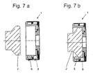
- the coupling 1 of an endoscope for an eyepiece funnel 2 of an optical device consists of three basic elements, namely an annular base body 3, further comprising an inner ring 4 screwed onto this base body 3 and thus non-rotatably connected, and one on the above-described system (consisting of the main body 3 and the inner ring 4) rotatably mounted outer ring. 5
- three locking elements 6 are arranged in the form of balls around the circumference, which are mounted radially movable in corresponding openings of the base body 3.
- the outer ring in corresponding recesses in the inner wall leaf springs 7, which extend substantially in the circumferential direction and are specially bent.
- a tension spring 8 is arranged in the form of a compression spring between the main body 3 and the outer ring 5.
- a locking device 9 is arranged between the main body 3 and the outer ring 5, which is shown in an enlarged scale separately in Fig. 3.
- This locking device 9 has a latching spring 10, which is arranged in the bottom of the outer ring 5.
- This latching spring 10 is bent so that it comes to lie positively in the latching position in a corresponding latching groove 11 in the base body 3.
- the locking device 9 still has a pin 12 which is mounted in the base body 3. One end of this pin 12 protrudes into the interior of the coupling 1, while the other end bears against the free end of the locking spring 10 designed as a leaf spring.
- the operation of the automatic clutch 1 is as follows:
- the ocular funnel 2 (FIG. 7a) can be inserted into the coupling 1 (FIG. 7b).
- the pin 12 is first pressed down, so that the latching spring 10 is moved out of the latching groove 11 of the base body 3.
- the outer ring 5 is automatically rotated with respect to the base body 3 (FIG. 6b and FIG. 8b).
- the locking elements 6 in the form of balls in the region of the leaf springs 7, so that the locking elements 6 are moved radially inwardly so that they come to lie positively on the funnel bevel of Okulartrichters 2.
- the leaf springs 7 do not yet develop the full contact pressure of the locking elements 6 on the Okulartrichter 2, so that it can be rotated by hand a little more.
- the outer ring 5 is moved a bit further, so that the leaf springs 7 exert the maximum compressive force on the locking elements 6 and thus on the slope of Okulartrichters 2, so that it held securely and non-rotatably by frictional engagement is.
- the working position is reached.
- the outer ring 5 is completely turned back starting from the locking position (FIG. 8c) by hand (FIG. 8a), so that the latching spring 10 of the locking device 9 engages in the latching groove 11 of the base body 3.
- the pin 12 is moved back into the interior of the coupling housing. In this position, the clutch 1 is ready to receive a Okulartrichter 2 again in the manner described above.
Landscapes
- Health & Medical Sciences (AREA)
- Life Sciences & Earth Sciences (AREA)
- Surgery (AREA)
- Engineering & Computer Science (AREA)
- Biomedical Technology (AREA)
- Heart & Thoracic Surgery (AREA)
- Pathology (AREA)
- Radiology & Medical Imaging (AREA)
- Nuclear Medicine, Radiotherapy & Molecular Imaging (AREA)
- Biophysics (AREA)
- Physics & Mathematics (AREA)
- Optics & Photonics (AREA)
- Medical Informatics (AREA)
- Molecular Biology (AREA)
- Animal Behavior & Ethology (AREA)
- General Health & Medical Sciences (AREA)
- Public Health (AREA)
- Veterinary Medicine (AREA)
- Mechanical Engineering (AREA)
- Endoscopes (AREA)
Claims (8)
- Accouplement (1) pour un endoscope destiné à être raccordé à un oculaire (2) d'un dispositif optique,
avec un corps de base (3) intérieur annulaire,
avec une bague extérieure (5) tournante sur le corps de base (3),
avec des éléments de verrouillage (6) montés dans le corps de base (3) qui, lors de la rotation de la bague extérieure (5), peuvent se déplacer radialement vers l'intérieur en appui contre l'oculaire (2) au moyen de surfaces de guidage et où un ressort tendeur (8) est disposé entre le corps de base (3) et la bague extérieure (5),
caractérisé par le fait
qu'en position ouverte de l'accouplement (1), corps de base (3) et bague extérieure (5) sont verrouillés contre la force du ressort tendeur (8) tendu au moyen d'un dispositif de verrouillage (9),
que corps de base (3) et bague extérieure (5) sont déverrouillables automatiquement par l'introduction de l'oculaire (2) dans l'accouplement (1) et tournent automatiquement, sous l'effet de la force du ressort tendeur (8) tendu, dans une position de fermeture dans laquelle les éléments de verrouillage (6) sont transférés dans la position de fermeture et que, en partant de la position de fermeture, on peut continuer à tourner manuellement la bague extérieure (5) dans une position dans laquelle les éléments de verrouillage (6) sont transférés dans une position de verrouillage définitive. - Accouplement selon la revendication précédente,
caractérisé par le fait
que les éléments de verrouillage (6) sont des billes. - Accouplement selon l'une des revendications précédentes,
caractérisé par le fait
que le ressort tendeur (8) est un ressort de compression ou de traction. - Accouplement selon l'une des revendications précédentes,
caractérisé par le fait
qu'il est prévu comme dispositif de verrouillage (9) entre le corps de base (3) et la bague extérieure (5) un ressort d'encliquetage (10) qui est monté dans une pièce et encliqueté par engagement positif dans l'autre pièce dans la position d'ouverture de l'accouplement (1) et
qu'il est prévu en outre une tige (12) qui dépasse à l'intérieur de l'accouplement (1) à travers le corps de base (3) et qui, lors de l'introduction de l'oculaire (2) dans l'accouplement (1), est déplaçable par l'oculaire (2) de telle manière que le ressort d'encliquetage (10) soit transférable dans la position de déverrouillage. - Accouplement selon la revendication 4,
caractérisé par le fait
que le ressort d'encliquetage (10) est un ressort à lame. - Accouplement selon la revendication 4 ou 5,
caractérisé par le fait
que le ressort d'encliquetage (10) est monté dans le fond de la bague extérieure (5) et que le corps de base (3) présente une rainure d'encliquetage (11) pour le ressort d'encliquetage (10). - Accouplement selon l'une des revendications précédentes,
caractérisé par le fait
qu'un ressort à lame (7) s'étendant essentiellement en direction circonférentielle est associé chaque fois dans la bague extérieure (5) à un élément de verrouillage (6) du corps de base (3) de manière à exercer une pression sur l'élément de verrouillage (6) associé. - Accouplement selon la revendication 7,
caractérisé par le fait
que la caractéristique de ressort du ressort à lame (7) est telle que, en partant de la position d'ouverture, la force de pression du ressort à lame (7) sur les éléments de verrouillage (6) augmente au fur et à mesure que l'on tourne progressivement la bague extérieure (5).
Applications Claiming Priority (2)
| Application Number | Priority Date | Filing Date | Title |
|---|---|---|---|
| DE20317828U | 2003-11-18 | ||
| DE20317828U DE20317828U1 (de) | 2003-11-18 | 2003-11-18 | Kupplung für ein Endoskop |
Publications (2)
| Publication Number | Publication Date |
|---|---|
| EP1533645A1 EP1533645A1 (fr) | 2005-05-25 |
| EP1533645B1 true EP1533645B1 (fr) | 2006-08-09 |
Family
ID=31725247
Family Applications (1)
| Application Number | Title | Priority Date | Filing Date |
|---|---|---|---|
| EP04026358A Expired - Lifetime EP1533645B1 (fr) | 2003-11-18 | 2004-11-05 | Dispositif d'accouplement pour endoscope |
Country Status (3)
| Country | Link |
|---|---|
| EP (1) | EP1533645B1 (fr) |
| AT (1) | ATE336022T1 (fr) |
| DE (2) | DE20317828U1 (fr) |
Cited By (1)
| Publication number | Priority date | Publication date | Assignee | Title |
|---|---|---|---|---|
| WO2016130692A1 (fr) * | 2015-02-12 | 2016-08-18 | The General Hospital Corporation | Appareil et procédé pour la fixation d'accessoires d'endoscope |
Family Cites Families (5)
| Publication number | Priority date | Publication date | Assignee | Title |
|---|---|---|---|---|
| DE6926837U (de) * | 1969-07-07 | 1969-11-13 | Wolf Gmbh Richard | Kupplung zwischen einer endoskop-optik und dem objektiv einer kamera |
| FR2459645A1 (fr) * | 1979-06-27 | 1981-01-16 | Wolf Gmbh Richard | Accouplement rapide entre une camera et un systeme optique d'endoscope |
| US4697894A (en) * | 1984-11-30 | 1987-10-06 | Olympus Optical Co., Ltd. | Connection device for connecting an associated unit to an eyepiece section of an endoscope |
| JPH10243917A (ja) * | 1997-03-07 | 1998-09-14 | Olympus Optical Co Ltd | 内視鏡接続装置 |
| JPH119549A (ja) * | 1997-06-25 | 1999-01-19 | Union Optical Co Ltd | 内視鏡用カメラ接続装置 |
-
2003
- 2003-11-18 DE DE20317828U patent/DE20317828U1/de not_active Expired - Lifetime
-
2004
- 2004-11-05 EP EP04026358A patent/EP1533645B1/fr not_active Expired - Lifetime
- 2004-11-05 DE DE502004001150T patent/DE502004001150D1/de not_active Expired - Lifetime
- 2004-11-05 AT AT04026358T patent/ATE336022T1/de not_active IP Right Cessation
Cited By (1)
| Publication number | Priority date | Publication date | Assignee | Title |
|---|---|---|---|---|
| WO2016130692A1 (fr) * | 2015-02-12 | 2016-08-18 | The General Hospital Corporation | Appareil et procédé pour la fixation d'accessoires d'endoscope |
Also Published As
| Publication number | Publication date |
|---|---|
| EP1533645A1 (fr) | 2005-05-25 |
| DE502004001150D1 (de) | 2006-09-21 |
| ATE336022T1 (de) | 2006-09-15 |
| DE20317828U1 (de) | 2004-02-12 |
Similar Documents
| Publication | Publication Date | Title |
|---|---|---|
| DE3342497C2 (fr) | ||
| WO2009118070A1 (fr) | Machine-outil électrique | |
| DE102009050089A1 (de) | Arretierbare Stellvorrichtung zum Verstellen einer Abseheneinrichtung | |
| DE102007030310A1 (de) | Kupplungsvorrichtung zum Festlegen medizinischer Instrumente an einer Haltevorrichtung | |
| EP3773311B1 (fr) | Adaptateur de montage pour la fixation d'une housse stérile à un microscope, microscope utilisable avec un tel adaptateur et système pourvu d'un tel microscope et d'un tel adaptateur | |
| DE102009036334B4 (de) | Vorrichtung zum Setzen eines Befestigungselementes | |
| DE2216749B2 (de) | Zahnärztliches Handstück zum Anschluss an einen Mikromotor | |
| DE19514098A1 (de) | Kupplung für Rohrschaftinstrumente | |
| EP3741287B1 (fr) | Coupleur d'endoscope pour une caméra et procédé de couplage et de découplage d'un endoscope doté d'une caméra au moyen d'un coupleur d'endoscope ainsi que caméra pourvue de coupleur d'endoscope | |
| EP2401953B1 (fr) | Dispositif de couplage pour une connexion amovible entre l'oculaire d'un endoscope et une caméra | |
| EP2965843A1 (fr) | Mandrin et dispositif de serrage doté de fonction de changement rapide | |
| DE102011011244A1 (de) | Medizinisches Instrument | |
| DE3341876A1 (de) | Kupplung zur verbindung optischer geraete | |
| EP0784178A1 (fr) | Dispositif d'étanchement d'un tuyau de protection | |
| EP0372099B1 (fr) | Lance compacte ayant une sécurité contre la rotation des tubes | |
| DE102013200127A1 (de) | Aneurysma-Clip | |
| DE4425705A1 (de) | Endoskopisches Instrument | |
| EP1533645A1 (fr) | Dispositif d'accouplement pour endoscope | |
| DE19712645C1 (de) | Kupplung zum Kuppeln zweier optischer Einrichtungen | |
| DE10306014A1 (de) | Drehdämpfer und Beifahrergriffvorrichtung | |
| EP0973688B1 (fr) | Robinet de soutirage | |
| DE19910457B4 (de) | Chirurgisches Schiebeschaftinstrument | |
| DE102010015997A1 (de) | Scharnier | |
| EP1752197B1 (fr) | Sonde d'avalanche | |
| DE102013016273B4 (de) | Verriegelungsvorrichtung zum abdichten eines anzeigeinstruments |
Legal Events
| Date | Code | Title | Description |
|---|---|---|---|
| PUAI | Public reference made under article 153(3) epc to a published international application that has entered the european phase |
Free format text: ORIGINAL CODE: 0009012 |
|
| AK | Designated contracting states |
Kind code of ref document: A1 Designated state(s): AT BE BG CH CY CZ DE DK EE ES FI FR GB GR HU IE IS IT LI LU MC NL PL PT RO SE SI SK TR |
|
| AX | Request for extension of the european patent |
Extension state: AL HR LT LV MK YU |
|
| 17P | Request for examination filed |
Effective date: 20050907 |
|
| AKX | Designation fees paid |
Designated state(s): AT BE BG CH CY CZ DE DK EE ES FI FR GB GR HU IE IS IT LI LU MC NL PL PT RO SE SI SK TR |
|
| GRAP | Despatch of communication of intention to grant a patent |
Free format text: ORIGINAL CODE: EPIDOSNIGR1 |
|
| GRAS | Grant fee paid |
Free format text: ORIGINAL CODE: EPIDOSNIGR3 |
|
| GRAA | (expected) grant |
Free format text: ORIGINAL CODE: 0009210 |
|
| AK | Designated contracting states |
Kind code of ref document: B1 Designated state(s): AT BE BG CH CY CZ DE DK EE ES FI FR GB GR HU IE IS IT LI LU MC NL PL PT RO SE SI SK TR |
|
| PG25 | Lapsed in a contracting state [announced via postgrant information from national office to epo] |
Ref country code: SI Free format text: LAPSE BECAUSE OF FAILURE TO SUBMIT A TRANSLATION OF THE DESCRIPTION OR TO PAY THE FEE WITHIN THE PRESCRIBED TIME-LIMIT Effective date: 20060809 Ref country code: IS Free format text: LAPSE BECAUSE OF FAILURE TO SUBMIT A TRANSLATION OF THE DESCRIPTION OR TO PAY THE FEE WITHIN THE PRESCRIBED TIME-LIMIT Effective date: 20060809 Ref country code: GB Free format text: LAPSE BECAUSE OF FAILURE TO SUBMIT A TRANSLATION OF THE DESCRIPTION OR TO PAY THE FEE WITHIN THE PRESCRIBED TIME-LIMIT Effective date: 20060809 Ref country code: IT Free format text: LAPSE BECAUSE OF FAILURE TO SUBMIT A TRANSLATION OF THE DESCRIPTION OR TO PAY THE FEE WITHIN THE PRESCRIBED TIME-LIMIT;WARNING: LAPSES OF ITALIAN PATENTS WITH EFFECTIVE DATE BEFORE 2007 MAY HAVE OCCURRED AT ANY TIME BEFORE 2007. THE CORRECT EFFECTIVE DATE MAY BE DIFFERENT FROM THE ONE RECORDED. Effective date: 20060809 Ref country code: FI Free format text: LAPSE BECAUSE OF FAILURE TO SUBMIT A TRANSLATION OF THE DESCRIPTION OR TO PAY THE FEE WITHIN THE PRESCRIBED TIME-LIMIT Effective date: 20060809 Ref country code: RO Free format text: LAPSE BECAUSE OF FAILURE TO SUBMIT A TRANSLATION OF THE DESCRIPTION OR TO PAY THE FEE WITHIN THE PRESCRIBED TIME-LIMIT Effective date: 20060809 Ref country code: NL Free format text: LAPSE BECAUSE OF FAILURE TO SUBMIT A TRANSLATION OF THE DESCRIPTION OR TO PAY THE FEE WITHIN THE PRESCRIBED TIME-LIMIT Effective date: 20060809 Ref country code: IE Free format text: LAPSE BECAUSE OF FAILURE TO SUBMIT A TRANSLATION OF THE DESCRIPTION OR TO PAY THE FEE WITHIN THE PRESCRIBED TIME-LIMIT Effective date: 20060809 Ref country code: PL Free format text: LAPSE BECAUSE OF FAILURE TO SUBMIT A TRANSLATION OF THE DESCRIPTION OR TO PAY THE FEE WITHIN THE PRESCRIBED TIME-LIMIT Effective date: 20060809 Ref country code: SK Free format text: LAPSE BECAUSE OF FAILURE TO SUBMIT A TRANSLATION OF THE DESCRIPTION OR TO PAY THE FEE WITHIN THE PRESCRIBED TIME-LIMIT Effective date: 20060809 Ref country code: CZ Free format text: LAPSE BECAUSE OF FAILURE TO SUBMIT A TRANSLATION OF THE DESCRIPTION OR TO PAY THE FEE WITHIN THE PRESCRIBED TIME-LIMIT Effective date: 20060809 |
|
| REG | Reference to a national code |
Ref country code: GB Ref legal event code: FG4D Free format text: NOT ENGLISH |
|
| REG | Reference to a national code |
Ref country code: CH Ref legal event code: EP |
|
| REG | Reference to a national code |
Ref country code: IE Ref legal event code: FG4D Free format text: LANGUAGE OF EP DOCUMENT: GERMAN |
|
| REF | Corresponds to: |
Ref document number: 502004001150 Country of ref document: DE Date of ref document: 20060921 Kind code of ref document: P |
|
| PG25 | Lapsed in a contracting state [announced via postgrant information from national office to epo] |
Ref country code: BG Free format text: LAPSE BECAUSE OF FAILURE TO SUBMIT A TRANSLATION OF THE DESCRIPTION OR TO PAY THE FEE WITHIN THE PRESCRIBED TIME-LIMIT Effective date: 20061109 Ref country code: SE Free format text: LAPSE BECAUSE OF FAILURE TO SUBMIT A TRANSLATION OF THE DESCRIPTION OR TO PAY THE FEE WITHIN THE PRESCRIBED TIME-LIMIT Effective date: 20061109 Ref country code: DK Free format text: LAPSE BECAUSE OF FAILURE TO SUBMIT A TRANSLATION OF THE DESCRIPTION OR TO PAY THE FEE WITHIN THE PRESCRIBED TIME-LIMIT Effective date: 20061109 |
|
| PG25 | Lapsed in a contracting state [announced via postgrant information from national office to epo] |
Ref country code: ES Free format text: LAPSE BECAUSE OF FAILURE TO SUBMIT A TRANSLATION OF THE DESCRIPTION OR TO PAY THE FEE WITHIN THE PRESCRIBED TIME-LIMIT Effective date: 20061120 |
|
| PG25 | Lapsed in a contracting state [announced via postgrant information from national office to epo] |
Ref country code: MC Free format text: LAPSE BECAUSE OF NON-PAYMENT OF DUE FEES Effective date: 20061130 Ref country code: BE Free format text: LAPSE BECAUSE OF NON-PAYMENT OF DUE FEES Effective date: 20061130 |
|
| PG25 | Lapsed in a contracting state [announced via postgrant information from national office to epo] |
Ref country code: PT Free format text: LAPSE BECAUSE OF FAILURE TO SUBMIT A TRANSLATION OF THE DESCRIPTION OR TO PAY THE FEE WITHIN THE PRESCRIBED TIME-LIMIT Effective date: 20070109 |
|
| NLV1 | Nl: lapsed or annulled due to failure to fulfill the requirements of art. 29p and 29m of the patents act | ||
| GBV | Gb: ep patent (uk) treated as always having been void in accordance with gb section 77(7)/1977 [no translation filed] |
Effective date: 20060809 |
|
| REG | Reference to a national code |
Ref country code: IE Ref legal event code: FD4D |
|
| EN | Fr: translation not filed | ||
| PLBE | No opposition filed within time limit |
Free format text: ORIGINAL CODE: 0009261 |
|
| STAA | Information on the status of an ep patent application or granted ep patent |
Free format text: STATUS: NO OPPOSITION FILED WITHIN TIME LIMIT |
|
| 26N | No opposition filed |
Effective date: 20070510 |
|
| BERE | Be: lapsed |
Owner name: SCHINDLER ENDOSKOPIE TECHNOLOGIE G.M.B.H. Effective date: 20061130 |
|
| PG25 | Lapsed in a contracting state [announced via postgrant information from national office to epo] |
Ref country code: AT Free format text: LAPSE BECAUSE OF NON-PAYMENT OF DUE FEES Effective date: 20061105 |
|
| PG25 | Lapsed in a contracting state [announced via postgrant information from national office to epo] |
Ref country code: GR Free format text: LAPSE BECAUSE OF FAILURE TO SUBMIT A TRANSLATION OF THE DESCRIPTION OR TO PAY THE FEE WITHIN THE PRESCRIBED TIME-LIMIT Effective date: 20061110 Ref country code: FR Free format text: LAPSE BECAUSE OF FAILURE TO SUBMIT A TRANSLATION OF THE DESCRIPTION OR TO PAY THE FEE WITHIN THE PRESCRIBED TIME-LIMIT Effective date: 20070511 |
|
| PG25 | Lapsed in a contracting state [announced via postgrant information from national office to epo] |
Ref country code: EE Free format text: LAPSE BECAUSE OF FAILURE TO SUBMIT A TRANSLATION OF THE DESCRIPTION OR TO PAY THE FEE WITHIN THE PRESCRIBED TIME-LIMIT Effective date: 20060809 |
|
| PG25 | Lapsed in a contracting state [announced via postgrant information from national office to epo] |
Ref country code: TR Free format text: LAPSE BECAUSE OF FAILURE TO SUBMIT A TRANSLATION OF THE DESCRIPTION OR TO PAY THE FEE WITHIN THE PRESCRIBED TIME-LIMIT Effective date: 20060809 Ref country code: HU Free format text: LAPSE BECAUSE OF FAILURE TO SUBMIT A TRANSLATION OF THE DESCRIPTION OR TO PAY THE FEE WITHIN THE PRESCRIBED TIME-LIMIT Effective date: 20070210 Ref country code: LU Free format text: LAPSE BECAUSE OF NON-PAYMENT OF DUE FEES Effective date: 20061105 |
|
| PG25 | Lapsed in a contracting state [announced via postgrant information from national office to epo] |
Ref country code: FR Free format text: LAPSE BECAUSE OF FAILURE TO SUBMIT A TRANSLATION OF THE DESCRIPTION OR TO PAY THE FEE WITHIN THE PRESCRIBED TIME-LIMIT Effective date: 20060809 Ref country code: CY Free format text: LAPSE BECAUSE OF FAILURE TO SUBMIT A TRANSLATION OF THE DESCRIPTION OR TO PAY THE FEE WITHIN THE PRESCRIBED TIME-LIMIT Effective date: 20060809 |
|
| REG | Reference to a national code |
Ref country code: CH Ref legal event code: PL |
|
| PG25 | Lapsed in a contracting state [announced via postgrant information from national office to epo] |
Ref country code: CH Free format text: LAPSE BECAUSE OF NON-PAYMENT OF DUE FEES Effective date: 20081130 Ref country code: LI Free format text: LAPSE BECAUSE OF NON-PAYMENT OF DUE FEES Effective date: 20081130 |
|
| REG | Reference to a national code |
Ref country code: DE Ref legal event code: R082 Ref document number: 502004001150 Country of ref document: DE Representative=s name: MEPAT PATENTANWAELTE, DR. MEHL-MIKUS, GOY, DR., DE |
|
| PGFP | Annual fee paid to national office [announced via postgrant information from national office to epo] |
Ref country code: DE Payment date: 20231214 Year of fee payment: 20 |
|
| REG | Reference to a national code |
Ref country code: DE Ref legal event code: R071 Ref document number: 502004001150 Country of ref document: DE |