EP1533583A2 - Eclairage intérieur pour appareil à conditionnement de température utilisant une diode électroluminescente (DEL) comme source lumineuse - Google Patents
Eclairage intérieur pour appareil à conditionnement de température utilisant une diode électroluminescente (DEL) comme source lumineuse Download PDFInfo
- Publication number
- EP1533583A2 EP1533583A2 EP04027051A EP04027051A EP1533583A2 EP 1533583 A2 EP1533583 A2 EP 1533583A2 EP 04027051 A EP04027051 A EP 04027051A EP 04027051 A EP04027051 A EP 04027051A EP 1533583 A2 EP1533583 A2 EP 1533583A2
- Authority
- EP
- European Patent Office
- Prior art keywords
- light
- interior lighting
- interior
- circuit arrangement
- emitting diode
- Prior art date
- Legal status (The legal status is an assumption and is not a legal conclusion. Google has not performed a legal analysis and makes no representation as to the accuracy of the status listed.)
- Withdrawn
Links
- 230000003750 conditioning effect Effects 0.000 title 1
- 230000003287 optical effect Effects 0.000 claims description 7
- 229910052751 metal Inorganic materials 0.000 abstract description 2
- 239000002184 metal Substances 0.000 abstract description 2
- 239000003990 capacitor Substances 0.000 description 9
- 239000000758 substrate Substances 0.000 description 6
- 238000004804 winding Methods 0.000 description 5
- 238000010586 diagram Methods 0.000 description 3
- 206010014357 Electric shock Diseases 0.000 description 2
- 229910052782 aluminium Inorganic materials 0.000 description 2
- XAGFODPZIPBFFR-UHFFFAOYSA-N aluminium Chemical compound [Al] XAGFODPZIPBFFR-UHFFFAOYSA-N 0.000 description 2
- 235000013361 beverage Nutrition 0.000 description 2
- 238000001816 cooling Methods 0.000 description 2
- 230000005611 electricity Effects 0.000 description 2
- 239000011521 glass Substances 0.000 description 2
- 238000005286 illumination Methods 0.000 description 2
- 230000010354 integration Effects 0.000 description 2
- 239000004033 plastic Substances 0.000 description 2
- 239000004417 polycarbonate Substances 0.000 description 2
- 229920000515 polycarbonate Polymers 0.000 description 2
- 238000005496 tempering Methods 0.000 description 2
- 230000003247 decreasing effect Effects 0.000 description 1
- 230000001419 dependent effect Effects 0.000 description 1
- 238000001514 detection method Methods 0.000 description 1
- 238000005516 engineering process Methods 0.000 description 1
- 230000005669 field effect Effects 0.000 description 1
- 238000001914 filtration Methods 0.000 description 1
- 230000004907 flux Effects 0.000 description 1
- 238000009499 grossing Methods 0.000 description 1
- 244000144980 herd Species 0.000 description 1
- 238000002955 isolation Methods 0.000 description 1
- 238000012423 maintenance Methods 0.000 description 1
- 238000000034 method Methods 0.000 description 1
- 229910052754 neon Inorganic materials 0.000 description 1
- GKAOGPIIYCISHV-UHFFFAOYSA-N neon atom Chemical compound [Ne] GKAOGPIIYCISHV-UHFFFAOYSA-N 0.000 description 1
- 230000001681 protective effect Effects 0.000 description 1
- 230000005855 radiation Effects 0.000 description 1
- 230000001105 regulatory effect Effects 0.000 description 1
- 230000000630 rising effect Effects 0.000 description 1
Images



Classifications
-
- F—MECHANICAL ENGINEERING; LIGHTING; HEATING; WEAPONS; BLASTING
- F25—REFRIGERATION OR COOLING; COMBINED HEATING AND REFRIGERATION SYSTEMS; HEAT PUMP SYSTEMS; MANUFACTURE OR STORAGE OF ICE; LIQUEFACTION SOLIDIFICATION OF GASES
- F25D—REFRIGERATORS; COLD ROOMS; ICE-BOXES; COOLING OR FREEZING APPARATUS NOT OTHERWISE PROVIDED FOR
- F25D27/00—Lighting arrangements
-
- F—MECHANICAL ENGINEERING; LIGHTING; HEATING; WEAPONS; BLASTING
- F21—LIGHTING
- F21V—FUNCTIONAL FEATURES OR DETAILS OF LIGHTING DEVICES OR SYSTEMS THEREOF; STRUCTURAL COMBINATIONS OF LIGHTING DEVICES WITH OTHER ARTICLES, NOT OTHERWISE PROVIDED FOR
- F21V33/00—Structural combinations of lighting devices with other articles, not otherwise provided for
- F21V33/0004—Personal or domestic articles
- F21V33/0044—Household appliances, e.g. washing machines or vacuum cleaners
-
- F—MECHANICAL ENGINEERING; LIGHTING; HEATING; WEAPONS; BLASTING
- F21—LIGHTING
- F21W—INDEXING SCHEME ASSOCIATED WITH SUBCLASSES F21K, F21L, F21S and F21V, RELATING TO USES OR APPLICATIONS OF LIGHTING DEVICES OR SYSTEMS
- F21W2131/00—Use or application of lighting devices or systems not provided for in codes F21W2102/00-F21W2121/00
- F21W2131/30—Lighting for domestic or personal use
- F21W2131/305—Lighting for domestic or personal use for refrigerators
-
- F—MECHANICAL ENGINEERING; LIGHTING; HEATING; WEAPONS; BLASTING
- F21—LIGHTING
- F21Y—INDEXING SCHEME ASSOCIATED WITH SUBCLASSES F21K, F21L, F21S and F21V, RELATING TO THE FORM OR THE KIND OF THE LIGHT SOURCES OR OF THE COLOUR OF THE LIGHT EMITTED
- F21Y2115/00—Light-generating elements of semiconductor light sources
- F21Y2115/10—Light-emitting diodes [LED]
-
- F—MECHANICAL ENGINEERING; LIGHTING; HEATING; WEAPONS; BLASTING
- F25—REFRIGERATION OR COOLING; COMBINED HEATING AND REFRIGERATION SYSTEMS; HEAT PUMP SYSTEMS; MANUFACTURE OR STORAGE OF ICE; LIQUEFACTION SOLIDIFICATION OF GASES
- F25D—REFRIGERATORS; COLD ROOMS; ICE-BOXES; COOLING OR FREEZING APPARATUS NOT OTHERWISE PROVIDED FOR
- F25D2500/00—Problems to be solved
- F25D2500/02—Geometry problems
Definitions
- the present invention relates to interior lighting for household appliances, in particular a temperature control device with a light emitting diode as a light source and a Cooling device with such a light source, further exhaust systems such Exhaust hoods for kitchens with such interior lighting.
- interior lighting for home appliances in particular Tempering devices designed with a light bulb or a neon tube.
- the object of the invention is thus, the above-mentioned disadvantages of the prior the technology in interior lighting for home appliances, in particular Avoid tempering and interior lighting available To provide that is reliable, gives a better light intensity, low maintenance and minimizes the risk of electric shock.
- the object of the invention is achieved in that in a Indoor lighting for household appliances, preferably temperature control, in particular Refrigerators, is provided, the interior lighting with at least one Design illuminants, wherein the illuminant is a light emitting diode, which in the Essentially emitted white light.
- a light-emitting diode instead of the previously used bulbs, such as a light bulb, has the advantage that low power lines from, for example, an external power supply to the interior of the Household appliance, especially the refrigerator can be pulled to to supply the LED with electricity.
- An introduction of 230 volt lines For example, in the refrigerator interior is when using a LED as illuminant for illuminating a refrigerator interior then no longer necessary.
- the Interior lighting includes a switching device with which the lighting For example, when opening the refrigerator door can be turned on.
- the contactless or Non-contact switch integrated into the circuit of the interior lighting become.
- the use of a light-emitting diode has the further advantage that one Turning the light bulb on and off not only with a mechanical Switch as before can be done, but also with the help of at different Sites arranged sensor devices. These sensor devices are in turn electrically connected to the light emitting diode.
- a sensor device For example, distance sensors, brightness sensors or even come Vibrating sensors into consideration.
- the circuit arrangement may in a preferred embodiment a circuit arrangement with a current control, in which the brightness of the lighting means by changing the provided current at the LED can be adjusted.
- the Circuit arrangement comprises a switching device which has a first current for a high brightness of the LED and a second current for a low Luminous intensity of the LED provides.
- the power supply of the light emitting diode with a Constant current source is characterized by a constant current output and is in particular by a current-controlled Drive circuit obtained, which includes a current control, which z. B. at decreasing mains voltage readjusts the current so that the drive current the LED is always constant.
- a Constant current is the luminosity, that is the radiant power of the LED always the same.
- the power consumption of the circuit is lower than at Interior lighting according to the prior art.
- Another advantage of Arrangement according to the invention is that the luminous efficacy by a multiple is higher than in systems with the usual bulbs such as for example, a light bulb.
- a light source for example, preferably a Luxeon TM III Star LED Lumi LEDS Lightening LLC, 370 West Rembles Road, San Jose, CA. 95131, USA related. This bulb gives a power of 1 or 3 watts from.
- FIG. 1 shows a luminous means according to the invention.
- the invention Illuminant is a white light LED 1, which is arranged on a support 3 is.
- the rear wall is marked with reference numeral 12, the front wall with the Door to open with 14, the top with 16 and the bottom with 18.
- the luminous body which is designed as a white-light LED, is on a Carrier 3.1, at an inclination of about 20 ° relative to the top wall 16th arranged.
- the depth A of the interior, such as a refrigerator in the illustrated embodiment is preferably in the range 30 to 50 cm, preferred especially at 40 cm; the height B preferably in the range 60 to 70 cm, preferably at 66 cm.
- FIG. 3 shows an embodiment of the invention with two luminous bodies.
- the one light-emitting diode 1.1 is arranged on the ceiling 18, to the Light-emitting diode 1.2 is arranged on the front wall 14.
- Both light-emitting diodes 1.1, 1.2 are mounted on support 3.1, 3.2 at an angle ⁇ .
- the depth A lies preferably in the range 30 to 50 cm., Particularly preferably at 40 cm; the height B preferably in the range 120 to 180 cm, preferably in particular 140 cm.
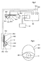
- FIG 4 is a schematic representation of an inventive Circuit arrangement with two light-emitting diodes 1.1, 1.2 as a luminous element, a Power supply 100 and a switch assembly 102 shown.
- the power supply 100 is on a mains voltage of 230 volts connected and preferably has a Transformer, for example, the mains voltage to a voltage of 3.5 Volts transformed.
- the power supply 100 is according to the invention outside the Interior of a household appliance, such as the refrigerator interior arranged to lay the power lines in, for example, the Refrigerator interior to avoid.
- Connected to the mains is a manual one Pressure switch, which is electrically connected to the power supply, and these on or off, for example when the refrigerator door is open or closed becomes.
- the LED is in a filament housing 106.1, 106.2 housed.
- the luminous body housing is preferably a Plastic housing made of polycarbonate.
- the light housing includes a Carrier substrate 108.1, 108.2 for the light-emitting diode 1.1, 1.2 and a cover 110.1, 110.2 for the light-emitting diodes 1.1, 1.2.
- the carrier substrate preferably comprises a heat sink, for example a metal block, in particular a Aluminum block or an aluminum substrate.
- the cover 110.1, 110.2 is off made of a plastic, in particular of a polycarbonate.
- the Carrier substrate 108.1, 108.2 of the respective light-emitting diodes 1.1, 1.2 comprise a slanted section 208.1, 208.2 on the light emitting diode 1.1, 1.2 below an angle ⁇ on the carrier substrate 108.1, 108.2 are arranged.
- the carrier substrate comprises two stops 210.1, 210.2 and 212.1, 212.2, which serve to receive the cover 110.1, 110.2.
- the cover in turn has a so-called optical region 220.1, 220.2 for the light distribution of the radiated from the light emitting diode 1.1, 1.2 White light.
- the manual Pressure switch by appropriate sensors, such as a Brightness sensor can be replaced without departing from the spirit of the invention becomes.
- the illustrated two Luminaire or two light-emitting diodes 1.1, 1.2 at more than two different Make in the refrigerator to provide such a luminous body.
- one Design with only one lamp would be conceivable. This only needs the power supply are designed accordingly.
- FIG. 5 shows a luminous body housing 106.1, 106.2 according to the invention
- the optical range for the light distribution is 220.1 characterized.
- the LED is marked with 1.1.
- the optical area 110.1 describes the area in which the light of the light-emitting diode 1.1 is emitted and, for example, is directed to the interior of the refrigerator interior.
- the non-optical region for the light distribution of the cover 110.1 is 222.1 characterized. In this area, the cover 110.1 is, for example frosted, so that no white light can escape to the outside. This is only in the optical range 220.1 possible, which is designed to be translucent.
- FIG. 6A the circuitry for the power supply that is outside of the Refrigerator interior is arranged, shown.
- the power connections 500.1, 500.2 is the mains voltage of 230 volts.
- transformer 502 the Mains voltage to a voltage of 8.48 volts at output 504 to ground rechucked.
- the transformer 502 is followed by a rectifier circuit 506 on.
- the voltage applied to terminal 504 to ground is 8.48 volts to the lying in the interior of the refrigerator circuitry, the in Figure 6b is shown applied.
- the circuit 508 serves to the light emitting diode 510.1, 510.2 with a constant current at the present constant voltage to supply, so that the LEDs 510.1, 510.2 always white light same Radiate brightness.
- circuits shown in FIGS. 6A and 6B are Circuits is an LED light emitting diode with a power of one watt It is also possible to supply a constant current Circuit for powering a white light LED with high Performance which is a dimming, i. a stepless power setting of the LED allows to output. This is especially true for wine cabinets from Meaning, since wine refrigerators have a transparent glass door, and there a continuous dimming of the light should be made possible.
- FIG. 7A is a block diagram of another embodiment of a circuit shown.
- 602 designates the network connection, 604 the network filter and 606 the rectifier.
- a transformer 608 connected to the rectifier is preferred outside of Refrigerator interior a transformer 608 connected.
- the Transformer which is also referred to as a transformer, is itself through again controlled a so-called Simple Switcher 610.
- a simple Switcher 610 designated component is preferably a Switching regulator TNY254 from the company Power Integrations, which belongs to a switching regulator families the output power up to a total load of max. Can achieve 10 watts, belongs.
- the TNY254 used in the present embodiment may have a Output power of up to 4 watts and is thus in the operation of a 3 Watt Power - LED not yet operated to its power limit.
- the Switching regulator TNY254 has a powerful internal power MOSFET - Switching transistor of a dielectric strength of up to 700V DC (DC).
- the switching regulator TNY254 is a small - power switching regulator, which in direct mains operation with a wide input voltage range from 85V to 265V AC (AC voltage) can be supplied.
- the voltage regulator TNY254 is powered by an internal 44KHz oscillator clocked and thus works extremely power failure free regarding EMC (Electromagnetic Compatibility), which is only inexpensive Net filter measures required.
- the required output characteristics are passed through easy ON and OFF switching achieved. This eliminates the Transformer, d. H. at the transformer 608 another so-called bias winding.
- the Self-consumption of the switching regulator is extremely energy efficient; it amounts to only 60/30 mW at 110 VAC / 230 VAC (AC voltage).
- the TNY 254 switching regulator has an internal current limitation, one thermal overload device and undervoltage detection. Of the Switching regulator is preferred with a specially adapted thereto transformer KNY254-5-3 of the manufacturer Azurri akin.
- the switching regulator TNY254 forms together with the transformer 608 in particular the transformer KNY254-5-3 a so-called "safety unit".
- the switching regulator 610 also becomes the same in FIGS. 7B, 8A and 8B Reference number marked. Also in the case of FIGS. 7B, 8A and 8B related switching regulators 610 are, but are not limited to, to those of the type TNY254. Depending on the power of the LED, for example Switching regulator of similar type, eg. B. Switching regulator TNY253, TNY 255 of the Fa. Power Integrations are used.
- the by the transformer or the Transformer 608 to a mains voltage of about 4 volts down-transformed voltage is on the other side of the transformer 608th rectified and smoothed in a circuit 612.
- Embodiments will be a light-emitting diodes 614. with electric current provided.
- the power of the LEDs is 3 watts.
- the current or Voltage limiter is designated 615, the optocoupler 616.
- FIG. 8A is the detailed circuit with the individual electronic Building components of a circuit based on a block diagram according to Figure 7A shown.
- 704 denotes the section of the electrical Circuit corresponding to the line filter, 716 the primary controlled switching regulator, 718 the galvanic isolation, 720 the elements of the current and Voltage limitation. As well as 722 the filtering or smoothing of the voltage the LED (LED).
- the circuit is described in detail below become.
- the network input Voltage across a fuse 1000 and the following Line filter for balanced interference, consisting of the components capacitor 1002, 1004 and the throttle 1006 supplied.
- the capacitors are Safety capacitors of the X1 or Y1 protection class. These are specially approved components for this application with tested DIN - Dielectric strength. These components protect the power grid against potential occurring interference pulses of the switching regulator.
- the safety resistor 1000 destroyed itself at more than 10 times overcurrent.
- varistor 1008 which is a voltage dependent resistor, which is the subsequent circuit of the Protects the mains side against overvoltage pulses (eg lightning, etc.). After that becomes the AC mains voltage with the rectifier 1010 to a DC voltage of 325V DC rectified during operation with 230 VAC.
- One Electrolytic Capacitor 1012 (ELKO) smooths the "ripples" of the AC voltage to a pure DC voltage. Thus the Elko is not loaded too fast and In order to be damaged, the series resistor 1014 is in use.
- the switching regulator is supplied via the primary winding of the transformer 608 and over the capacitor 1016 with voltage and now switches with its internal Power - FET the DC voltage in the 44 KHz - clock against its ground point.
- This creates an electromagnetic alternating current field in the primary winding, that about the turn ratio of the transformer, that is the number of Windings primary and secondary, a galvanically isolated AC voltage couples to the output side of the transformer.
- the selected transformer 608 about 3.3 to 6.0 VAC transfer. It draws its necessary output power from the parallel connection the two secondary windings. This is sufficient for the operation of the LED.
- the emitting diode of the optocoupler 1036 changes its brightness with increasing voltage and blocks again the enable input of the switching regulator by the rising luminous flux 610, since only feedback is given by means of light. Due to the blocked enable input of the switching regulator, the switching regulator will suspend a few switching cycles so that the permissible output voltage is not exceeded. Thereafter, the output voltage is again smaller, the transmitter diode darker again and the switching regulator is enabled and clocks again until the permissible upper voltage limit is reached again. The control mechanism is done again. In the circuit according to the invention, however, the LED is only regulated to the maximum permissible current and not to the voltage, which is why the so-called "Sens resistors" 1038 and 1040 are also used.
- the capacitor 1043 provides for the potential bonding between primary and Secondary side. It must have the same security requirements as those already meet described capacitors 1002 and 1004.
- FIG. 7B shows the block diagram of a further alternative embodiment of FIG Invention, the dimming, d. H. a stepless power setting the LED allows. This is especially true for wine fridges from Meaning, since these often have a glass door and there a stepless Dimming of the light should be possible.
- the dimming by further Components made. Essentially, this is done with another Field effect transistor 1100 and an optocoupler 1102 and a galvanic separate PWM 1104 (pulse width modulator) with which the brightness of the Power - LED can be steplessly dimmed.
- PWM 1104 pulse width modulator
- FIG. 8B analogous to FIG. 8A, a circuit is described in detail in FIG Figure 7 B shown circuit of a light emitting diode 614 (LED) shown with dimming. Same components as in FIG. 8A are given the same reference numerals characterized. The functioning of the components is detailed in the Description of Figure 8A described. The additional components are with the Reference numerals 1300, 1302, 1304, 1306, 1308 and 1310. she serve for stepless dimming of the LED 614.
- Light-emitting diodes for example, two light-emitting diodes, which are parallel or in series are connected, be provided. This is apparent to the skilled person without inventive step.
- the invention provides an improved for the first time Interior lighting for household appliances, in particular temperature control devices, such as For example, refrigerators, freezers, freezers or wine fridges to disposal.
- the invention is also suitable for the interior lighting of herds, Beverage storage facilities, such as a beverage bar or for use in cooker hoods without being limited thereto.
- the Invention is characterized on the one hand by a very high brightness yield a low power consumption, on the other Avoid high voltage lines inside the temperature control unit completely and the arrangement shows only a low heat radiation when switched on Light.
Landscapes
- Engineering & Computer Science (AREA)
- General Engineering & Computer Science (AREA)
- Chemical & Material Sciences (AREA)
- Combustion & Propulsion (AREA)
- Physics & Mathematics (AREA)
- Mechanical Engineering (AREA)
- Thermal Sciences (AREA)
- Circuit Arrangement For Electric Light Sources In General (AREA)
Applications Claiming Priority (4)
| Application Number | Priority Date | Filing Date | Title |
|---|---|---|---|
| DE20318059U DE20318059U1 (de) | 2003-11-21 | 2003-11-21 | Innenbeleuchtung für Kühlgeräte mit LED |
| DE20318059U | 2003-11-21 | ||
| DE10358071 | 2003-12-10 | ||
| DE10358071A DE10358071A1 (de) | 2003-11-21 | 2003-12-10 | Innenbeleuchtung für ein Temperiergerät mit einer Leuchtdiode als Lichtquelle |
Publications (1)
| Publication Number | Publication Date |
|---|---|
| EP1533583A2 true EP1533583A2 (fr) | 2005-05-25 |
Family
ID=34436344
Family Applications (1)
| Application Number | Title | Priority Date | Filing Date |
|---|---|---|---|
| EP04027051A Withdrawn EP1533583A2 (fr) | 2003-11-21 | 2004-11-13 | Eclairage intérieur pour appareil à conditionnement de température utilisant une diode électroluminescente (DEL) comme source lumineuse |
Country Status (1)
| Country | Link |
|---|---|
| EP (1) | EP1533583A2 (fr) |
Cited By (2)
| Publication number | Priority date | Publication date | Assignee | Title |
|---|---|---|---|---|
| WO2008135428A3 (fr) * | 2007-05-08 | 2009-01-15 | Bsh Bosch Siemens Hausgeraete | Éclairage pour un appareil réfrigérant à porte transparente |
| DE102013001623A1 (de) * | 2013-01-30 | 2014-07-31 | Liebherr-Hausgeräte Ochsenhausen GmbH | Kühl- und /oder Gefriergerät |
-
2004
- 2004-11-13 EP EP04027051A patent/EP1533583A2/fr not_active Withdrawn
Cited By (4)
| Publication number | Priority date | Publication date | Assignee | Title |
|---|---|---|---|---|
| WO2008135428A3 (fr) * | 2007-05-08 | 2009-01-15 | Bsh Bosch Siemens Hausgeraete | Éclairage pour un appareil réfrigérant à porte transparente |
| RU2469248C2 (ru) * | 2007-05-08 | 2012-12-10 | Бсх Бош Унд Сименс Хаусгерете Гмбх | Освещение холодильного аппарата с прозрачной дверкой |
| CN101842652B (zh) * | 2007-05-08 | 2013-05-29 | Bsh博世和西门子家用器具有限公司 | 用于具有透明的门的制冷装置的照明装置 |
| DE102013001623A1 (de) * | 2013-01-30 | 2014-07-31 | Liebherr-Hausgeräte Ochsenhausen GmbH | Kühl- und /oder Gefriergerät |
Similar Documents
| Publication | Publication Date | Title |
|---|---|---|
| JP6258951B2 (ja) | 回路装置及び回路装置を備えるledランプ | |
| DE102016100710A1 (de) | Bestromungsbaugruppe, Leuchte und Beleuchtungssystem | |
| DE112012003338T5 (de) | Wechselstrom-Gleichstrom-LED-Beleuchtungsvorrichtungen, -Systeme und -Verfahren | |
| DE112015006564T5 (de) | System und Verfahren zur Steuerung von Festkörperlampen | |
| DE112014000697T5 (de) | Antriebsschaltung, Beleuchtungslichtquelle, und Beleuchtungsvorrichtung | |
| DE102015117732A1 (de) | Lichtmodulationssteuereinheit, Beleuchtungssystem und eine Anlagenvorrichtung | |
| WO2011083117A2 (fr) | Procédé combiné pour faire fonctionner un élément luminescent électrique et circuit d'exploitation | |
| DE102014111085A1 (de) | Beleuchtungsbaugruppe und diese verwendende Beleuchtungsvorrichtung | |
| DE102010043013B4 (de) | Beleuchtungsvorrichtung und Verfahren zum Beleuchten | |
| DE202013004095U1 (de) | LED-Beleuchtungssystem | |
| EP2425681B1 (fr) | Circuit de pilotage pour un del | |
| EP1533583A2 (fr) | Eclairage intérieur pour appareil à conditionnement de température utilisant une diode électroluminescente (DEL) comme source lumineuse | |
| DE102016125902B3 (de) | Flimmerfreier Dimmschalter für eine diffuse Lichtquelle | |
| US10045407B1 (en) | Dual input voltage constant power indicator | |
| DE102012200320A1 (de) | Schaltung für ein Haushaltsgerät | |
| WO2000065880A1 (fr) | Source lumineuse constituee de plusieurs diodes electroluminescentes montees les unes derriere les autres | |
| EP2425679B1 (fr) | Circuit d'excitation pour une led | |
| US20080224630A1 (en) | Dimming circuit for controlling electrical power | |
| DE112009004860T5 (de) | Dimmersystem und Dimmverfahren | |
| EP2420108B1 (fr) | Circuit de commande pour leds | |
| DE112014006816B4 (de) | Adaptiver Leistungsausgleich in LED-Lampen | |
| WO2010121925A1 (fr) | Dispositif d'éclairage doté d'une fonction d'éclairage variable dans le temps | |
| EP2273849A2 (fr) | Commande à DEL | |
| DE102011086446A1 (de) | Benutzersteuerung für eine LED | |
| DE10358071A1 (de) | Innenbeleuchtung für ein Temperiergerät mit einer Leuchtdiode als Lichtquelle |
Legal Events
| Date | Code | Title | Description |
|---|---|---|---|
| PUAI | Public reference made under article 153(3) epc to a published international application that has entered the european phase |
Free format text: ORIGINAL CODE: 0009012 |
|
| AK | Designated contracting states |
Kind code of ref document: A2 Designated state(s): AT BE BG CH CY CZ DE DK EE ES FI FR GB GR HU IE IS IT LI LU MC NL PL PT RO SE SI SK TR |
|
| AX | Request for extension of the european patent |
Extension state: AL HR LT LV MK YU |
|
| STAA | Information on the status of an ep patent application or granted ep patent |
Free format text: STATUS: THE APPLICATION IS DEEMED TO BE WITHDRAWN |
|
| 18D | Application deemed to be withdrawn |
Effective date: 20080603 |