EP1533583A2 - Indoor lighting for a temperature conditioning apparatus using an LED as light source - Google Patents
Indoor lighting for a temperature conditioning apparatus using an LED as light source Download PDFInfo
- Publication number
- EP1533583A2 EP1533583A2 EP04027051A EP04027051A EP1533583A2 EP 1533583 A2 EP1533583 A2 EP 1533583A2 EP 04027051 A EP04027051 A EP 04027051A EP 04027051 A EP04027051 A EP 04027051A EP 1533583 A2 EP1533583 A2 EP 1533583A2
- Authority
- EP
- European Patent Office
- Prior art keywords
- light
- interior lighting
- interior
- circuit arrangement
- emitting diode
- Prior art date
- Legal status (The legal status is an assumption and is not a legal conclusion. Google has not performed a legal analysis and makes no representation as to the accuracy of the status listed.)
- Withdrawn
Links
- 230000003750 conditioning effect Effects 0.000 title 1
- 230000003287 optical effect Effects 0.000 claims description 7
- 229910052751 metal Inorganic materials 0.000 abstract description 2
- 239000002184 metal Substances 0.000 abstract description 2
- 239000003990 capacitor Substances 0.000 description 9
- 239000000758 substrate Substances 0.000 description 6
- 238000004804 winding Methods 0.000 description 5
- 238000010586 diagram Methods 0.000 description 3
- 206010014357 Electric shock Diseases 0.000 description 2
- 229910052782 aluminium Inorganic materials 0.000 description 2
- XAGFODPZIPBFFR-UHFFFAOYSA-N aluminium Chemical compound [Al] XAGFODPZIPBFFR-UHFFFAOYSA-N 0.000 description 2
- 235000013361 beverage Nutrition 0.000 description 2
- 238000001816 cooling Methods 0.000 description 2
- 230000005611 electricity Effects 0.000 description 2
- 239000011521 glass Substances 0.000 description 2
- 238000005286 illumination Methods 0.000 description 2
- 230000010354 integration Effects 0.000 description 2
- 239000004033 plastic Substances 0.000 description 2
- 239000004417 polycarbonate Substances 0.000 description 2
- 229920000515 polycarbonate Polymers 0.000 description 2
- 238000005496 tempering Methods 0.000 description 2
- 230000003247 decreasing effect Effects 0.000 description 1
- 230000001419 dependent effect Effects 0.000 description 1
- 238000001514 detection method Methods 0.000 description 1
- 238000005516 engineering process Methods 0.000 description 1
- 230000005669 field effect Effects 0.000 description 1
- 238000001914 filtration Methods 0.000 description 1
- 230000004907 flux Effects 0.000 description 1
- 238000009499 grossing Methods 0.000 description 1
- 244000144980 herd Species 0.000 description 1
- 238000002955 isolation Methods 0.000 description 1
- 238000012423 maintenance Methods 0.000 description 1
- 238000000034 method Methods 0.000 description 1
- 229910052754 neon Inorganic materials 0.000 description 1
- GKAOGPIIYCISHV-UHFFFAOYSA-N neon atom Chemical compound [Ne] GKAOGPIIYCISHV-UHFFFAOYSA-N 0.000 description 1
- 230000001681 protective effect Effects 0.000 description 1
- 230000005855 radiation Effects 0.000 description 1
- 230000001105 regulatory effect Effects 0.000 description 1
- 230000000630 rising effect Effects 0.000 description 1
Images



Classifications
-
- F—MECHANICAL ENGINEERING; LIGHTING; HEATING; WEAPONS; BLASTING
- F25—REFRIGERATION OR COOLING; COMBINED HEATING AND REFRIGERATION SYSTEMS; HEAT PUMP SYSTEMS; MANUFACTURE OR STORAGE OF ICE; LIQUEFACTION SOLIDIFICATION OF GASES
- F25D—REFRIGERATORS; COLD ROOMS; ICE-BOXES; COOLING OR FREEZING APPARATUS NOT OTHERWISE PROVIDED FOR
- F25D27/00—Lighting arrangements
-
- F—MECHANICAL ENGINEERING; LIGHTING; HEATING; WEAPONS; BLASTING
- F21—LIGHTING
- F21V—FUNCTIONAL FEATURES OR DETAILS OF LIGHTING DEVICES OR SYSTEMS THEREOF; STRUCTURAL COMBINATIONS OF LIGHTING DEVICES WITH OTHER ARTICLES, NOT OTHERWISE PROVIDED FOR
- F21V33/00—Structural combinations of lighting devices with other articles, not otherwise provided for
- F21V33/0004—Personal or domestic articles
- F21V33/0044—Household appliances, e.g. washing machines or vacuum cleaners
-
- F—MECHANICAL ENGINEERING; LIGHTING; HEATING; WEAPONS; BLASTING
- F21—LIGHTING
- F21W—INDEXING SCHEME ASSOCIATED WITH SUBCLASSES F21K, F21L, F21S and F21V, RELATING TO USES OR APPLICATIONS OF LIGHTING DEVICES OR SYSTEMS
- F21W2131/00—Use or application of lighting devices or systems not provided for in codes F21W2102/00-F21W2121/00
- F21W2131/30—Lighting for domestic or personal use
- F21W2131/305—Lighting for domestic or personal use for refrigerators
-
- F—MECHANICAL ENGINEERING; LIGHTING; HEATING; WEAPONS; BLASTING
- F21—LIGHTING
- F21Y—INDEXING SCHEME ASSOCIATED WITH SUBCLASSES F21K, F21L, F21S and F21V, RELATING TO THE FORM OR THE KIND OF THE LIGHT SOURCES OR OF THE COLOUR OF THE LIGHT EMITTED
- F21Y2115/00—Light-generating elements of semiconductor light sources
- F21Y2115/10—Light-emitting diodes [LED]
-
- F—MECHANICAL ENGINEERING; LIGHTING; HEATING; WEAPONS; BLASTING
- F25—REFRIGERATION OR COOLING; COMBINED HEATING AND REFRIGERATION SYSTEMS; HEAT PUMP SYSTEMS; MANUFACTURE OR STORAGE OF ICE; LIQUEFACTION SOLIDIFICATION OF GASES
- F25D—REFRIGERATORS; COLD ROOMS; ICE-BOXES; COOLING OR FREEZING APPARATUS NOT OTHERWISE PROVIDED FOR
- F25D2500/00—Problems to be solved
- F25D2500/02—Geometry problems
Definitions
- the present invention relates to interior lighting for household appliances, in particular a temperature control device with a light emitting diode as a light source and a Cooling device with such a light source, further exhaust systems such Exhaust hoods for kitchens with such interior lighting.
- interior lighting for home appliances in particular Tempering devices designed with a light bulb or a neon tube.
- the object of the invention is thus, the above-mentioned disadvantages of the prior the technology in interior lighting for home appliances, in particular Avoid tempering and interior lighting available To provide that is reliable, gives a better light intensity, low maintenance and minimizes the risk of electric shock.
- the object of the invention is achieved in that in a Indoor lighting for household appliances, preferably temperature control, in particular Refrigerators, is provided, the interior lighting with at least one Design illuminants, wherein the illuminant is a light emitting diode, which in the Essentially emitted white light.
- a light-emitting diode instead of the previously used bulbs, such as a light bulb, has the advantage that low power lines from, for example, an external power supply to the interior of the Household appliance, especially the refrigerator can be pulled to to supply the LED with electricity.
- An introduction of 230 volt lines For example, in the refrigerator interior is when using a LED as illuminant for illuminating a refrigerator interior then no longer necessary.
- the Interior lighting includes a switching device with which the lighting For example, when opening the refrigerator door can be turned on.
- the contactless or Non-contact switch integrated into the circuit of the interior lighting become.
- the use of a light-emitting diode has the further advantage that one Turning the light bulb on and off not only with a mechanical Switch as before can be done, but also with the help of at different Sites arranged sensor devices. These sensor devices are in turn electrically connected to the light emitting diode.
- a sensor device For example, distance sensors, brightness sensors or even come Vibrating sensors into consideration.
- the circuit arrangement may in a preferred embodiment a circuit arrangement with a current control, in which the brightness of the lighting means by changing the provided current at the LED can be adjusted.
- the Circuit arrangement comprises a switching device which has a first current for a high brightness of the LED and a second current for a low Luminous intensity of the LED provides.
- the power supply of the light emitting diode with a Constant current source is characterized by a constant current output and is in particular by a current-controlled Drive circuit obtained, which includes a current control, which z. B. at decreasing mains voltage readjusts the current so that the drive current the LED is always constant.
- a Constant current is the luminosity, that is the radiant power of the LED always the same.
- the power consumption of the circuit is lower than at Interior lighting according to the prior art.
- Another advantage of Arrangement according to the invention is that the luminous efficacy by a multiple is higher than in systems with the usual bulbs such as for example, a light bulb.
- a light source for example, preferably a Luxeon TM III Star LED Lumi LEDS Lightening LLC, 370 West Rembles Road, San Jose, CA. 95131, USA related. This bulb gives a power of 1 or 3 watts from.
- FIG. 1 shows a luminous means according to the invention.
- the invention Illuminant is a white light LED 1, which is arranged on a support 3 is.
- the rear wall is marked with reference numeral 12, the front wall with the Door to open with 14, the top with 16 and the bottom with 18.
- the luminous body which is designed as a white-light LED, is on a Carrier 3.1, at an inclination of about 20 ° relative to the top wall 16th arranged.
- the depth A of the interior, such as a refrigerator in the illustrated embodiment is preferably in the range 30 to 50 cm, preferred especially at 40 cm; the height B preferably in the range 60 to 70 cm, preferably at 66 cm.
- FIG. 3 shows an embodiment of the invention with two luminous bodies.
- the one light-emitting diode 1.1 is arranged on the ceiling 18, to the Light-emitting diode 1.2 is arranged on the front wall 14.
- Both light-emitting diodes 1.1, 1.2 are mounted on support 3.1, 3.2 at an angle ⁇ .
- the depth A lies preferably in the range 30 to 50 cm., Particularly preferably at 40 cm; the height B preferably in the range 120 to 180 cm, preferably in particular 140 cm.
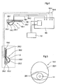
- FIG 4 is a schematic representation of an inventive Circuit arrangement with two light-emitting diodes 1.1, 1.2 as a luminous element, a Power supply 100 and a switch assembly 102 shown.
- the power supply 100 is on a mains voltage of 230 volts connected and preferably has a Transformer, for example, the mains voltage to a voltage of 3.5 Volts transformed.
- the power supply 100 is according to the invention outside the Interior of a household appliance, such as the refrigerator interior arranged to lay the power lines in, for example, the Refrigerator interior to avoid.
- Connected to the mains is a manual one Pressure switch, which is electrically connected to the power supply, and these on or off, for example when the refrigerator door is open or closed becomes.
- the LED is in a filament housing 106.1, 106.2 housed.
- the luminous body housing is preferably a Plastic housing made of polycarbonate.
- the light housing includes a Carrier substrate 108.1, 108.2 for the light-emitting diode 1.1, 1.2 and a cover 110.1, 110.2 for the light-emitting diodes 1.1, 1.2.
- the carrier substrate preferably comprises a heat sink, for example a metal block, in particular a Aluminum block or an aluminum substrate.
- the cover 110.1, 110.2 is off made of a plastic, in particular of a polycarbonate.
- the Carrier substrate 108.1, 108.2 of the respective light-emitting diodes 1.1, 1.2 comprise a slanted section 208.1, 208.2 on the light emitting diode 1.1, 1.2 below an angle ⁇ on the carrier substrate 108.1, 108.2 are arranged.
- the carrier substrate comprises two stops 210.1, 210.2 and 212.1, 212.2, which serve to receive the cover 110.1, 110.2.
- the cover in turn has a so-called optical region 220.1, 220.2 for the light distribution of the radiated from the light emitting diode 1.1, 1.2 White light.
- the manual Pressure switch by appropriate sensors, such as a Brightness sensor can be replaced without departing from the spirit of the invention becomes.
- the illustrated two Luminaire or two light-emitting diodes 1.1, 1.2 at more than two different Make in the refrigerator to provide such a luminous body.
- one Design with only one lamp would be conceivable. This only needs the power supply are designed accordingly.
- FIG. 5 shows a luminous body housing 106.1, 106.2 according to the invention
- the optical range for the light distribution is 220.1 characterized.
- the LED is marked with 1.1.
- the optical area 110.1 describes the area in which the light of the light-emitting diode 1.1 is emitted and, for example, is directed to the interior of the refrigerator interior.
- the non-optical region for the light distribution of the cover 110.1 is 222.1 characterized. In this area, the cover 110.1 is, for example frosted, so that no white light can escape to the outside. This is only in the optical range 220.1 possible, which is designed to be translucent.
- FIG. 6A the circuitry for the power supply that is outside of the Refrigerator interior is arranged, shown.
- the power connections 500.1, 500.2 is the mains voltage of 230 volts.
- transformer 502 the Mains voltage to a voltage of 8.48 volts at output 504 to ground rechucked.
- the transformer 502 is followed by a rectifier circuit 506 on.
- the voltage applied to terminal 504 to ground is 8.48 volts to the lying in the interior of the refrigerator circuitry, the in Figure 6b is shown applied.
- the circuit 508 serves to the light emitting diode 510.1, 510.2 with a constant current at the present constant voltage to supply, so that the LEDs 510.1, 510.2 always white light same Radiate brightness.
- circuits shown in FIGS. 6A and 6B are Circuits is an LED light emitting diode with a power of one watt It is also possible to supply a constant current Circuit for powering a white light LED with high Performance which is a dimming, i. a stepless power setting of the LED allows to output. This is especially true for wine cabinets from Meaning, since wine refrigerators have a transparent glass door, and there a continuous dimming of the light should be made possible.
- FIG. 7A is a block diagram of another embodiment of a circuit shown.
- 602 designates the network connection, 604 the network filter and 606 the rectifier.
- a transformer 608 connected to the rectifier is preferred outside of Refrigerator interior a transformer 608 connected.
- the Transformer which is also referred to as a transformer, is itself through again controlled a so-called Simple Switcher 610.
- a simple Switcher 610 designated component is preferably a Switching regulator TNY254 from the company Power Integrations, which belongs to a switching regulator families the output power up to a total load of max. Can achieve 10 watts, belongs.
- the TNY254 used in the present embodiment may have a Output power of up to 4 watts and is thus in the operation of a 3 Watt Power - LED not yet operated to its power limit.
- the Switching regulator TNY254 has a powerful internal power MOSFET - Switching transistor of a dielectric strength of up to 700V DC (DC).
- the switching regulator TNY254 is a small - power switching regulator, which in direct mains operation with a wide input voltage range from 85V to 265V AC (AC voltage) can be supplied.
- the voltage regulator TNY254 is powered by an internal 44KHz oscillator clocked and thus works extremely power failure free regarding EMC (Electromagnetic Compatibility), which is only inexpensive Net filter measures required.
- the required output characteristics are passed through easy ON and OFF switching achieved. This eliminates the Transformer, d. H. at the transformer 608 another so-called bias winding.
- the Self-consumption of the switching regulator is extremely energy efficient; it amounts to only 60/30 mW at 110 VAC / 230 VAC (AC voltage).
- the TNY 254 switching regulator has an internal current limitation, one thermal overload device and undervoltage detection. Of the Switching regulator is preferred with a specially adapted thereto transformer KNY254-5-3 of the manufacturer Azurri akin.
- the switching regulator TNY254 forms together with the transformer 608 in particular the transformer KNY254-5-3 a so-called "safety unit".
- the switching regulator 610 also becomes the same in FIGS. 7B, 8A and 8B Reference number marked. Also in the case of FIGS. 7B, 8A and 8B related switching regulators 610 are, but are not limited to, to those of the type TNY254. Depending on the power of the LED, for example Switching regulator of similar type, eg. B. Switching regulator TNY253, TNY 255 of the Fa. Power Integrations are used.
- the by the transformer or the Transformer 608 to a mains voltage of about 4 volts down-transformed voltage is on the other side of the transformer 608th rectified and smoothed in a circuit 612.
- Embodiments will be a light-emitting diodes 614. with electric current provided.
- the power of the LEDs is 3 watts.
- the current or Voltage limiter is designated 615, the optocoupler 616.
- FIG. 8A is the detailed circuit with the individual electronic Building components of a circuit based on a block diagram according to Figure 7A shown.
- 704 denotes the section of the electrical Circuit corresponding to the line filter, 716 the primary controlled switching regulator, 718 the galvanic isolation, 720 the elements of the current and Voltage limitation. As well as 722 the filtering or smoothing of the voltage the LED (LED).
- the circuit is described in detail below become.
- the network input Voltage across a fuse 1000 and the following Line filter for balanced interference, consisting of the components capacitor 1002, 1004 and the throttle 1006 supplied.
- the capacitors are Safety capacitors of the X1 or Y1 protection class. These are specially approved components for this application with tested DIN - Dielectric strength. These components protect the power grid against potential occurring interference pulses of the switching regulator.
- the safety resistor 1000 destroyed itself at more than 10 times overcurrent.
- varistor 1008 which is a voltage dependent resistor, which is the subsequent circuit of the Protects the mains side against overvoltage pulses (eg lightning, etc.). After that becomes the AC mains voltage with the rectifier 1010 to a DC voltage of 325V DC rectified during operation with 230 VAC.
- One Electrolytic Capacitor 1012 (ELKO) smooths the "ripples" of the AC voltage to a pure DC voltage. Thus the Elko is not loaded too fast and In order to be damaged, the series resistor 1014 is in use.
- the switching regulator is supplied via the primary winding of the transformer 608 and over the capacitor 1016 with voltage and now switches with its internal Power - FET the DC voltage in the 44 KHz - clock against its ground point.
- This creates an electromagnetic alternating current field in the primary winding, that about the turn ratio of the transformer, that is the number of Windings primary and secondary, a galvanically isolated AC voltage couples to the output side of the transformer.
- the selected transformer 608 about 3.3 to 6.0 VAC transfer. It draws its necessary output power from the parallel connection the two secondary windings. This is sufficient for the operation of the LED.
- the emitting diode of the optocoupler 1036 changes its brightness with increasing voltage and blocks again the enable input of the switching regulator by the rising luminous flux 610, since only feedback is given by means of light. Due to the blocked enable input of the switching regulator, the switching regulator will suspend a few switching cycles so that the permissible output voltage is not exceeded. Thereafter, the output voltage is again smaller, the transmitter diode darker again and the switching regulator is enabled and clocks again until the permissible upper voltage limit is reached again. The control mechanism is done again. In the circuit according to the invention, however, the LED is only regulated to the maximum permissible current and not to the voltage, which is why the so-called "Sens resistors" 1038 and 1040 are also used.
- the capacitor 1043 provides for the potential bonding between primary and Secondary side. It must have the same security requirements as those already meet described capacitors 1002 and 1004.
- FIG. 7B shows the block diagram of a further alternative embodiment of FIG Invention, the dimming, d. H. a stepless power setting the LED allows. This is especially true for wine fridges from Meaning, since these often have a glass door and there a stepless Dimming of the light should be possible.
- the dimming by further Components made. Essentially, this is done with another Field effect transistor 1100 and an optocoupler 1102 and a galvanic separate PWM 1104 (pulse width modulator) with which the brightness of the Power - LED can be steplessly dimmed.
- PWM 1104 pulse width modulator
- FIG. 8B analogous to FIG. 8A, a circuit is described in detail in FIG Figure 7 B shown circuit of a light emitting diode 614 (LED) shown with dimming. Same components as in FIG. 8A are given the same reference numerals characterized. The functioning of the components is detailed in the Description of Figure 8A described. The additional components are with the Reference numerals 1300, 1302, 1304, 1306, 1308 and 1310. she serve for stepless dimming of the LED 614.
- Light-emitting diodes for example, two light-emitting diodes, which are parallel or in series are connected, be provided. This is apparent to the skilled person without inventive step.
- the invention provides an improved for the first time Interior lighting for household appliances, in particular temperature control devices, such as For example, refrigerators, freezers, freezers or wine fridges to disposal.
- the invention is also suitable for the interior lighting of herds, Beverage storage facilities, such as a beverage bar or for use in cooker hoods without being limited thereto.
- the Invention is characterized on the one hand by a very high brightness yield a low power consumption, on the other Avoid high voltage lines inside the temperature control unit completely and the arrangement shows only a low heat radiation when switched on Light.
Landscapes
- Engineering & Computer Science (AREA)
- General Engineering & Computer Science (AREA)
- Chemical & Material Sciences (AREA)
- Combustion & Propulsion (AREA)
- Physics & Mathematics (AREA)
- Mechanical Engineering (AREA)
- Thermal Sciences (AREA)
- Circuit Arrangement For Electric Light Sources In General (AREA)
Abstract
Description
Die vorliegende Erfindung betrifft eine Innenbeleuchtung für Haushaltsgeräte, insbesondere ein Temperiergerät mit einer Leuchtdiode als Lichtquelle und einer Kühleinrichtung mit einer derartigen Lichtquelle, des weiteren Abluftsysteme wie Abzugshauben für Küchen mit einer derartigen Innenbeleuchtung.The present invention relates to interior lighting for household appliances, in particular a temperature control device with a light emitting diode as a light source and a Cooling device with such a light source, further exhaust systems such Exhaust hoods for kitchens with such interior lighting.
Bisher werden Innenbeleuchtungen für Haushaltsgeräte, insbesondere Temperiereinrichtungen mit einer Glühbirne oder einer Neonröhre ausgestaltet. Nachteilig an den bislang verwendeten Leuchtkörpern für die Innenbeleuchtung von Haushaltsgeräten, insbesondere Kühlgeräten, war, dass die 230 Volt-Zuleitungen für die Leuchtkörper in das Innere der Haushaltsgeräte, insbesondere der Kühlgeräte, geführt werden mussten.So far, interior lighting for home appliances, in particular Tempering devices designed with a light bulb or a neon tube. A disadvantage of the luminaires used for interior lighting of home appliances, especially refrigerators, that was the 230 volt supply lines for the filament into the interior of the household appliances, in particular the cooling units, had to be guided.
Dies stellte für Personen, die das Haushaltsgerät insbesondere den Kühlschrank bedienen, eine Gefahrenquelle hinsichtlich eines Stromschlagrisikos dar.This posed for persons, who the domestic appliance in particular the refrigerator operate, a source of danger with respect to a risk of electric shock.
Des weiteren nachteilig waren die hohe Wärmeentwicklung der Leuchtkörper im Betrieb, d. h. bei Aktivierung und die sehr schlechte Ausleuchtung des Innenraumes des Haushaltsgerätes, insbesondere des Kühlgerätes.Another disadvantage was the high heat of the luminous body in Operation, d. H. when activated and the very bad illumination of the Interior of the household appliance, in particular the refrigerator.
Aufgabe der Erfindung ist es somit, die oben aufgezeigten Nachteile des Standes der Technik bei Innenbeleuchtungen für Haushaltsgeräte, insbesondere Temperiereinrichtungen zu vermeiden und eine Innenbeleuchtung zur Verfügung zu stellen, die zuverlässig ist, eine bessere Lichtstärke abgibt, wartungsarm ist sowie das Risiko eines elektrischen Stromschlages minimiert.The object of the invention is thus, the above-mentioned disadvantages of the prior the technology in interior lighting for home appliances, in particular Avoid tempering and interior lighting available To provide that is reliable, gives a better light intensity, low maintenance and minimizes the risk of electric shock.
Die erfindungsgemäße Aufgabe wird dadurch gelöst, dass bei einer Innenbeleuchtung für Haushaltsgeräte, bevorzugt Temperiergeräte, insbesondere Kühlgeräte, vorgesehen wird, die Innenbeleuchtung mit wenigstens einem Leuchtmittel auszugestalten, wobei das Leuchtmittel eine Leuchtdiode ist, die im Wesentlichen Weißlicht emittiert. The object of the invention is achieved in that in a Indoor lighting for household appliances, preferably temperature control, in particular Refrigerators, is provided, the interior lighting with at least one Design illuminants, wherein the illuminant is a light emitting diode, which in the Essentially emitted white light.
Die Verwendung einer Leuchtdiode anstelle der bisher eingesetzten Leuchtmittel, wie beispielsweise einer Glühbirne, hat den Vorteil, dass Schwachstromleitungen von beispielsweise einem außen liegenden Netzteil in das Innere des Haushaltsgerätes, insbesondere des Kühlschrankes gezogen werden können, um die Leuchtdiode mit Strom zu versorgen. Ein Hineinführen von 230 Volt-Leitungen beispielsweise in den Kühlschrankinnenraum ist bei Verwendung einer Leuchtdiode als Leuchtmittel zur Beleuchtung eines Kühlschrankinnenraumes dann nicht mehr erforderlich.The use of a light-emitting diode instead of the previously used bulbs, such as a light bulb, has the advantage that low power lines from, for example, an external power supply to the interior of the Household appliance, especially the refrigerator can be pulled to to supply the LED with electricity. An introduction of 230 volt lines For example, in the refrigerator interior is when using a LED as illuminant for illuminating a refrigerator interior then no longer necessary.
In einer besonders vorteilhaften Ausgestaltung ist vorgesehen, dass die Innenbeleuchtung eine Schalteinrichtung umfasst, mit der die Beleuchtung beispielsweise beim Öffnen der Kühlschranktür eingeschaltet werden kann. Hierfür können die derzeit in Kühlschrankinnenräumen vorgesehenen kontaktlosen bzw. berührungslosen Schalter in den Stromkreis der Innenbeleuchtung integriert werden.In a particularly advantageous embodiment, it is provided that the Interior lighting includes a switching device with which the lighting For example, when opening the refrigerator door can be turned on. Therefor For example, the contactless or Non-contact switch integrated into the circuit of the interior lighting become.
Gegenüber den bisher verwandten Leuchtmitteln, wie beispielsweise einer Glühbirne, hat die Verwendung einer Leuchtdiode den weiteren Vorteil, dass ein Ein- und Ausschalten des Leuchtmittels nicht nur mit einem mechanischen Schalter wie bislang erfolgen kann, sondern auch mit Hilfe von an verschiedenen Stellen angeordneten Sensoreinrichtungen. Diese Sensoreinrichtungen sind wiederum elektrisch mit der Leuchtdiode verbunden. Als Sensoreinrichtung kommen beispielsweise Wegesensoren, Helligkeitssensoren oder auch Rüttelsensoren in Betracht.Compared to the previously used bulbs, such as a Light bulb, the use of a light-emitting diode has the further advantage that one Turning the light bulb on and off not only with a mechanical Switch as before can be done, but also with the help of at different Sites arranged sensor devices. These sensor devices are in turn electrically connected to the light emitting diode. As a sensor device For example, distance sensors, brightness sensors or even come Vibrating sensors into consideration.
In einer weiteren bevorzugten Ausgestaltung der Erfindung wird eine Schaltkreisanordnung für eine Innenbeleuchtung von Innenräumen von Haushaltsgeräten, bevorzugt Temperiergeräten, insbesondere Kühlschränken, zur Verfügung gestellt, die ein Netzteil, das bevorzugt entfernt von der Leuchtquelle, insbesondere außerhalb des Innenraumes eines Haushaltsgerätes angeordnet ist, umfasst. Die Schaltungsanordnung kann in einer bevorzugten Ausführungsform eine Schaltungsanordnung mit einer Stromregelung umfassen, in der die Helligkeit des Leuchtmittels durch Verändern des zur Verfügung gestellten Stromes an der Leuchtdiode eingestellt werden kann.In a further preferred embodiment of the invention is a Circuit arrangement for indoor lighting of interiors Domestic appliances, preferably temperature control devices, in particular refrigerators, for Provided a power supply, preferably removed from the light source, is arranged in particular outside the interior of a household appliance, includes. The circuit arrangement may in a preferred embodiment a circuit arrangement with a current control, in which the brightness of the lighting means by changing the provided current at the LED can be adjusted.
In einer besonders bevorzugten Ausführungsform ist es möglich, dass die Schaltungsanordnung eine Umschaltvorrichtung umfasst, die einen ersten Strom für eine hohe Helligkeit der Leuchtdiode und einen zweiten Strom für eine niedrige Leuchtstärke der Leuchtdiode zur Verfügung stellt.In a particularly preferred embodiment, it is possible that the Circuit arrangement comprises a switching device which has a first current for a high brightness of the LED and a second current for a low Luminous intensity of the LED provides.
Besonders bevorzugt erfolgt die Stromversorgung der Leuchtdiode mit einer Konstantstromquelle. Eine Konstantstromquelle zeichnet sich durch eine konstante Stromabgabe aus und wird insbesondere durch eine stromgesteuerte Ansteuerschaltung erhalten, die eine Stromregelung umfasst, welche z. B. bei abnehmender Netzspannung den Strom nachregelt, so dass der Ansteuerstrom der Leuchtdiode immer konstant ist. Durch die Versorgung mit einem Konstantstrom ist die Leuchtkraft, das heißt die Strahlungsleistung der Leuchtdiode stets gleich. Der Strombedarf der Schaltung ist geringer als bei Innenbeleuchtungen gemäß dem Stand der Technik. Ein weiterer Vorteil der erfindungsgemäßen Anordnung ist, dass die Lichtausbeute um ein Vielfaches höher ist, als bei Systemen mit den bisher üblichen Leuchtmitteln wie beispielsweise einer Glühbirne.Particularly preferably, the power supply of the light emitting diode with a Constant current source. A constant current source is characterized by a constant current output and is in particular by a current-controlled Drive circuit obtained, which includes a current control, which z. B. at decreasing mains voltage readjusts the current so that the drive current the LED is always constant. By supplying one Constant current is the luminosity, that is the radiant power of the LED always the same. The power consumption of the circuit is lower than at Interior lighting according to the prior art. Another advantage of Arrangement according to the invention is that the luminous efficacy by a multiple is higher than in systems with the usual bulbs such as for example, a light bulb.
Als Leuchtmittel wird beispielsweise bevorzugt eine Luxeon™ III Star-Leuchtdiode der Firma Lumi LEDS Lightening LLC, 370 Westremble Road, San Jose, CA 95131, USA verwandt. Dieses Leuchtmittel gibt eine Leistung von 1 bzw. 3 Watt ab.As a light source, for example, preferably a Luxeon ™ III Star LED Lumi LEDS Lightening LLC, 370 West Rembles Road, San Jose, CA. 95131, USA related. This bulb gives a power of 1 or 3 watts from.
Die vorliegende Erfindung wird im Folgenden anhand bevorzugter Ausführungsformen mit Bezug auf die Zeichnungen näher erläutert.The present invention will be described below with reference to preferred Embodiments with reference to the drawings explained in more detail.
Die Figuren zeigen:
- Fig. 1:
- eine erfindungsgemäße Innenbeleuchtung eines Haushaltsgerätes, insbesondere eines Temperiergerätes mit einer Leuchtdiode
- Fig. 2:
- Anordnung einer erfindungsgemäßen Leuchtdiode im Innenraum eines Haushaltsgerätes, insbesondere eines Temperiergerätes
- Fig. 3:
- Anordnung von zwei Leuchtdioden gemäß der Erfindung im Innenraum eines Haushaltsgerätes, insbesondere eines Temperiergerätes
- Fig. 4:
- Schaltungsanordnung für eine erfindungsgemäße Innenbeleuchtung im Innenraum eines Haushaltsgerätes, insbesondere eines Temperiergerätes
- Fig. 5:
- detaillierte Ansicht eines erfindungsgemäßen Leuchtkörpers mit Leuchtdiode und Abdeckung
- Fig. 6A-6B:
- detaillierte Ansicht einer Schaltungsanordnung für das Netzteil (Figur 6A) und für die Versorgung der Weißlicht-Leuchtdiode (Figur 6B)
- Fig. 7A-8B:
- zeigen alternative Schaltungsanordnungen zur Versorgung von Weißlicht-Leuchtdioden
- Fig. 1:
- an interior lighting according to the invention of a household appliance, in particular a temperature control device with a light emitting diode
- Fig. 2:
- Arrangement of a light-emitting diode according to the invention in the interior of a household appliance, in particular a temperature control device
- 3:
- Arrangement of two light emitting diodes according to the invention in the interior of a household appliance, in particular a temperature control
- 4:
- Circuit arrangement for an interior lighting according to the invention in the interior of a household appliance, in particular a temperature control
- Fig. 5:
- detailed view of a filament according to the invention with light emitting diode and cover
- FIGS. 6A-6B:
- detailed view of a circuit arrangement for the power supply unit (FIG. 6A) and for the supply of the white-light LED (FIG. 6B)
- FIGS. 7A-8B:
- show alternative circuit arrangements for the supply of white light LEDs
In Figur 1 ist ein erfindungsgemäßes Leuchtmittel gezeigt. Das erfindungsgemäße
Leuchtmittel ist eine Weißlicht-Leuchtdiode 1, die auf einem Träger 3 angeordnet
ist. Der Träger 3 ist um einen Winkel α gegenüber beispielsweise einer Innenwand
5 eines Innenraumes eines Haushaltsgerätes, insbesondere Temperiergerätes
geneigt. In vorliegendem Fall beträgt der Winkel α = 20°.FIG. 1 shows a luminous means according to the invention. The invention
Illuminant is a
In Figur 2 ist die Anordnung einer erfindungsgemäßen Lichtquelle im Innenraum
eines Haushaltsgerätes, insbesondere Temperiergerätes gezeigt. Der Innenraum
ist mit Bezugsziffer 10 gekennzeichnet. In Figure 2, the arrangement of a light source according to the invention in the interior
a household appliance, in particular temperature control unit shown. The interior
is marked with
Die Rückwand ist mit Bezugsziffer 12 gekennzeichnet, die Vorderwand mit der
Türe zum Öffnen mit 14, die Oberseite mit 16 und der Boden mit 18. Wie aus Figur
2 ersichtlich, ist der Leuchtkörper, der als Weißlicht-LED ausgebildet ist, auf einem
Träger 3.1, unter einer Neigung von ungefähr 20° gegenüber der Deckelwand 16
angeordnet. Die Tiefe A des Innenraumes, beispielsweise eines Kühlschrankes
bei der dargestellten Ausführungsform liegt bevorzugt im Bereich 30 bis 50 cm,
bevorzugt insbesondere bei 40 cm; die Höhe B bevorzugt im Bereich 60 bis 70
cm, bevorzugt insbesondere bei 66 cm.The rear wall is marked with
In Figur 3 ist eine Ausführungsform der Erfindung mit zwei Leuchtkörpern gezeigt.
Die eine Leuchtdiode 1.1 ist die an der Decke 18 angeordnet, die an die
Leuchtdiode 1.2 ist an der Vorderwand 14 angeordnet. Beide Leuchtdioden 1.1,
1.2 sind auf Träger 3.1, 3.2 unter einem Winkel α montiert. Gleiche Bauteile wie in
Figur 2 sind mit denselben Bezugsziffern gekennzeichnet. Die Tiefe A liegt
bevorzugt im Bereich 30 bis 50 cm., bevorzugt insbesondere bei 40 cm; die Höhe
B bevorzugt im Bereich 120 bis 180 cm, bevorzugt insbesondere bei 140 cm. Mit
einer derartigen Anordnung wird eine besonders gute Ausleuchtung des
Innenraumes beispielsweise eines Kühlschrankes mit einer Höhe größer 120 cm
erzielt.FIG. 3 shows an embodiment of the invention with two luminous bodies.
The one light-emitting diode 1.1 is arranged on the
In Figur 4 ist in schematischer Darstellung eine erfindungsgemäße
Schaltungsanordnung mit zwei Leuchtdioden 1.1, 1.2 als Leuchtkörper, einem
Netzteil 100 und einer Schalteranordnung 102 gezeigt. Das Netzteil 100 ist an
eine Netzspannung von 230 Volt angeschlossen und besitzt bevorzugt einen
Transformator, der die Netzspannung beispielsweise auf eine Spannung von 3,5
Volt umformt. Das Netzteil 100 ist gemäß der Erfindung außerhalb des
Innenraumes eines Haushaltsgerätes, beispielsweise des Kühlschrankinnenraums
angeordnet, um die Verlegung von Netzleitungen in beispielsweise das
Kühlschrankinnere zu vermeiden. An das Netz angeschlossen ist ein manueller
Druckschalter, der elektrisch mit dem Netzteil verbunden ist, und diese an- bzw.
ausschaltet, beispielsweise wenn die Kühlschranktür geöffnet oder geschlossen
wird. Auf der Niederspannungsseite des Netzteils befinden sich elektrische
Leitungen 104.1, 104.2, 104.3, 104.4, die die Leuchtdioden 1.1, 1.2 mit
elektrischem Strom versorgen. Die Leuchtdiode ist in einem Leuchtkörpergehäuse
106.1, 106.2 untergebracht. Das Leuchtkörpergehäuse ist bevorzugt ein
Kunststoffgehäuse aus Polycarbonat. Das Leuchtgehäuse umfasst ein
Trägersubstrat 108.1, 108.2 für die Leuchtdiode 1.1, 1.2 sowie eine Abdeckung
110.1, 110.2 für die Leuchtdioden 1.1, 1.2. Das Trägersubstrat umfasst bevorzugt
einen Kühlkörper, beispielsweise ein Metallblock, insbesondere ein
Aluminiumblock oder ein Aluminiumsubstrat. Die Abdeckung 110.1, 110.2 ist aus
einem Kunststoff gefertigt, insbesondere aus einem Polycarbonat. Das
Trägersubstrat 108.1, 108.2 der jeweiligen Leuchtdioden 1.1, 1.2 umfassen einen
schräg gestellten Abschnitt 208.1, 208.2 auf den die Leuchtdiode 1.1, 1.2 unter
einem Winkel α auf dem Trägersubstrat 108.1, 108.2 angeordnet sind. Des
weiteren umfasst das Trägersubstrat zwei Anschläge 210.1, 210.2 sowie 212.1,
212.2, die dazu dienen, die Abdeckung 110.1, 110.2 aufzunehmen.In Figure 4 is a schematic representation of an inventive
Circuit arrangement with two light-emitting diodes 1.1, 1.2 as a luminous element, a
Die Abdeckung seinerseits besitzt einen sogenannten optischen Bereich 220.1, 220.2 für die Lichtverteilung des von der Leuchtdiode 1.1, 1.2 abgestrahlten Weißlichtes. Bei Ausgestaltungen der Erfindung mit sogenannten Sensoreinrichtungen zur Betätigung der Innenbeleuchtung, kann der manuelle Druckschalter durch entsprechende Sensoren, beispielsweise einen Helligkeitssensor ersetzt werden, ohne dass der Gedanke der Erfindung verlassen wird. Selbstverständlich ist es auch möglich, anstelle der dargestellten zwei Leuchtkörper bzw. zwei Leuchtdioden 1.1, 1.2 an mehr als zwei unterschiedlichen Stellen im Kühlschrank einen derartigen Leuchtkörper vorzusehen. Auch eine Ausgestaltung mit nur einem Leuchtkörper wäre denkbar. Hierzu muss lediglich das Netzteil entsprechend ausgelegt werden.The cover in turn has a so-called optical region 220.1, 220.2 for the light distribution of the radiated from the light emitting diode 1.1, 1.2 White light. In embodiments of the invention with so-called Sensor devices for operating the interior lighting, the manual Pressure switch by appropriate sensors, such as a Brightness sensor can be replaced without departing from the spirit of the invention becomes. Of course it is also possible, instead of the illustrated two Luminaire or two light-emitting diodes 1.1, 1.2 at more than two different Make in the refrigerator to provide such a luminous body. Also one Design with only one lamp would be conceivable. This only needs the power supply are designed accordingly.
In Figur 5 ist ein erfindungsgemäßes Leuchtkörpergehäuse 106.1, 106.2 mit Leuchtdiode 1.1, 1.2 in der Draufsicht sowie umgebender Abdeckung 110.1, 110.2 detaillierter gezeigt. Der optische Bereich für die Lichtverteilung ist mit 220.1 gekennzeichnet. Die Leuchtdiode ist mit 1.1 gekennzeichnet. Der optische Bereich 110.1 beschreibt den Bereich, in den das Licht der Leuchtdiode 1.1 abgestrahlt und beispielsweise in das Innere des Kühlschrankinnenraumes geleitet wird. Der nicht optische Bereich für die Lichtverteilung der Abdeckung 110.1 ist mit 222.1 gekennzeichnet. In diesem Bereich ist die Abdeckung 110.1 beispielsweise mattiert, so dass keinerlei Weißlicht nach außen dringen kann. Dies ist lediglich im optischen Bereich 220.1 möglich, der lichtdurchlässig ausgestaltet ist.FIG. 5 shows a luminous body housing 106.1, 106.2 according to the invention Light-emitting diode 1.1, 1.2 in plan view and surrounding cover 110.1, 110.2 shown in more detail. The optical range for the light distribution is 220.1 characterized. The LED is marked with 1.1. The optical area 110.1 describes the area in which the light of the light-emitting diode 1.1 is emitted and, for example, is directed to the interior of the refrigerator interior. Of the non-optical region for the light distribution of the cover 110.1 is 222.1 characterized. In this area, the cover 110.1 is, for example frosted, so that no white light can escape to the outside. This is only in the optical range 220.1 possible, which is designed to be translucent.
In Figur 6A ist die Schaltungsanordnung für das Netzteil, das außerhalb des
Kühlschrankinnenraumes angeordnet ist, gezeigt. An den Netzanschlüssen 500.1,
500.2 liegt die Netzspannung von 230 Volt an. Im Transformator 502 wird die
Netzspannung auf eine Spannung von 8,48 Volt am Ausgang 504 gegenüber Erde
umgespannt. An den Transformator 502 schließt sich eine Gleichrichterschaltung
506 an.In Figure 6A, the circuitry for the power supply that is outside of the
Refrigerator interior is arranged, shown. At the power connections 500.1,
500.2 is the mains voltage of 230 volts. In
Die an der Klemme 504 gegenüber Erde anliegende Spannung von 8,48 Volt wird
an die im Innenraum des Kühlschrankes liegende Schaltungsanordnung, die in
Figur 6b gezeigt ist, angelegt. Die Schaltung 508 dient dazu, die Leuchtdiode
510.1, 510.2 mit einem konstanten Strom bei vorliegender konstanter Spannung
zu versorgen, so dass die Leuchtdioden 510.1, 510.2 stets Weißlicht gleicher
Helligkeit abstrahlen.The voltage applied to
Während es sich bei den in den Figuren 6A und 6B gezeigten Schaltungen um Schaltungen handelt, die eine LED-Leuchtdiode mit einer Leistung von einem Watt mit einem konstanten Strom versorgen, ist es auch möglich eine Schaltungsanordnung zur Stromversorgung einer Weißlicht-Leuchtdiode mit hoher Leistung die eine Dimmung, d.h. eine stufenlose Leistungseinstellung der Leuchtdiode ermöglicht, auszugeben. Dies ist insbesondere für Weinschränke von Bedeutung, da Weinkühlschränke eine transparente Glastür aufweisen, und dort ein stufenloses Abdimmen des Lichtes ermöglicht werden soll.While the circuits shown in FIGS. 6A and 6B are Circuits is an LED light emitting diode with a power of one watt It is also possible to supply a constant current Circuit for powering a white light LED with high Performance which is a dimming, i. a stepless power setting of the LED allows to output. This is especially true for wine cabinets from Meaning, since wine refrigerators have a transparent glass door, and there a continuous dimming of the light should be made possible.
In Figur 7A ist ein Blockschaltbild einer weiteren Ausführungsform einer Schaltung
gezeigt. Hierbei bezeichnet 602 den Netzanschluss, 604 den Netzfilter sowie 606
den Gleichrichter. An den Gleichrichter ist bevorzugt außerhalb des
Kühlschrankinnenraumes ein Transformator 608 angeschlossen. Der
Transformator, der auch als Übertrager bezeichnet wird, wird selbst wieder durch
einen sogenannten Simple Switcher 610 gesteuert. Bei dem in Fig. 7A als simple
Switcher 610 bezeichneten Bauteil handelt es sich bevorzugt um einen
Schaltregler TNY254 der Fa. Power Integrations, der zu einer Schaltreglerfamilien
die Ausgangsleistung bis zu einer Gesamtlast von max. 10 Watt erzielen können,
gehört. Der im vorliegenden Ausführungsbeispiel eingesetzte TNY254 kann eine
Ausgangsleistung von bis zu 4 Watt erzielen und ist somit bei dem Betrieb einer 3
Watt Power - LED noch nicht bis an seine Leistungsgrenze betrieben. Der
Schaltregler TNY254 besitzt einen leistungsstarken, internen Power MOSFET -
Schaltransistor der eine Spannungsfestigkeit von bis zu 700V DC
(Gleichspannung) aufweist. Bei dem Schaltregler TNY254 handelt es sich um
einen Klein - Leistungs - Schaltregler, der in direktem Netzbetrieb mit einem
weiten Eingangs-Spannungsbereich von 85V bis 265 V AC (Wechselspannung)
versorgt werden kann. Der Spannungsregler TNY254 wird von einem internen
44KHz - Oszillator getaktet und arbeitet somit äußerst netzstörungsfrei hinsichtlich
EMV (elektromagnetische Verträglichkeit), was nur kostengünstige
Netzfiltermaßnahmen erforderlich macht. Im Gegensatz zu Schaltreglern gemäß
dem Stand der Technik werden die erforderlichen Ausgangskennwerte durch
einfaches EIN- und AUS - Schalten erzielt. Dadurch entfällt beim
Übertrager, d. h. beim Transformator 608 eine weitere, sog. Bias - Windung. Die
Eigenleistungsaufnahme des Schaltreglers ist äußerst energieeffizient; sie beträgt
nur 60 / 30 mW bei 110 VAC / 230 VAC (Wechselspannung).FIG. 7A is a block diagram of another embodiment of a circuit
shown. Here, 602 designates the network connection, 604 the network filter and 606
the rectifier. To the rectifier is preferred outside of
Refrigerator interior a
Weiterhin besitzt der Schaltregler TNY 254 eine interne Strombegrenzung, eine thermische Überlastungseinrichtung und eine Unterspannungserkennung. Der Schaltregler wird bevorzugt mit einem speziell hierauf abgestimmten Übertrager KNY254-5-3 des Herstellers Azurri verwandt.Furthermore, the TNY 254 switching regulator has an internal current limitation, one thermal overload device and undervoltage detection. Of the Switching regulator is preferred with a specially adapted thereto transformer KNY254-5-3 of the manufacturer Azurri akin.
Der Schaltregler TNY254 bildet zusammen mit dem Übertrager 608 im Speziellen
den Übertrager KNY254-5-3 eine sogenannte "Sicherheits-Einheit". The switching regulator TNY254 forms together with the
Der Schaltregler 610 wird auch in den Figuren 7B, 8A und 8B mit derselben
Bezugsziffer gekennzeichnet. Auch bei den in den Figuren 7B, 8A und 8B
verwandten Schaltreglern 610 handelt es sich ohne hierauf beschränkt zu sein,
um solche vom Typ TNY254. Je nach Leistung der LED können beispielsweise
Schaltregler von ähnlichem Typ, z. B. Schaltregler TNY253, TNY 255 der Fa.
Power Integrations zum Einsatz kommen. Die durch den Übertrager bzw. den
Transformator 608 auf eine Netzspannung von ungefähr 4 Volt
herabtransformierte Spannung wird auf der anderen Seite des Transformators 608
in einer Schaltung 612 gleichgerichtet und geglättet. In den in Figur 7A gezeigten
Ausführungsbeispielen wird eine Leuchtdioden 614. mit elektrischem Strom
versorgt. Die Leistung der Leuchtdioden beträgt 3 Watt. Der Strom- bzw.
Spannungsbegrenzer ist mit 615 bezeichnet, der Optokoppler mit 616.The
In Figur 8A ist die detaillierte Schaltung mit den einzelnen elektronischen
Baukomponenten einer Schaltung aufbauend auf einem Blockschaltbild gemäß
Figur 7A gezeigt. Hierbei bezeichnet 704 den Abschnitt der elektrischen
Schaltung, der dem Netzfilter entspricht, 716 den primär gesteuerten Schaltregler,
718 die galvanische Trennung, 720 die Elemente der Strom- und
Spannungsbegrenzung. Sowie 722 die Filterung bzw. Glättung der Spannung an
der Leuchtdiode (LED). Nachfolgend soll die Schaltung detailliert beschrieben
werden. Bei der in Figur 7 B gezeigten Schaltung wird die Netz - Eingangs -
Spannung über einen Sicherungswiderstand 1000 sowie dem darauffolgenden
Netzfilter für symmetrische Störungen, bestehend aus den Bauteilen Kondensator
1002, 1004 und die Drossel 1006 zugeführt. Bei den Kondensatoren handelt es
sich um Sicherheits - Kondensatoren der X1 bzw. Y1 - Schutzklasse. Das sind
besonders zugelassene Bauteile für diesen Anwendungsfall mit geprüfter DIN -
Spannungsfestigkeit. Diese Bauteile schützen das Stromnetz gegen eventuell
auftretende Störpulse des Schaltreglers. Der Sicherheitswiderstand 1000 zerstört
sich selbst bei mehr als 10-fachem Überstrom. In Figure 8A is the detailed circuit with the individual electronic
Building components of a circuit based on a block diagram according to
Figure 7A shown. Here, 704 denotes the section of the electrical
Circuit corresponding to the line filter, 716 the primary controlled switching regulator,
718 the galvanic isolation, 720 the elements of the current and
Voltage limitation. As well as 722 the filtering or smoothing of the voltage
the LED (LED). The circuit is described in detail below
become. In the circuit shown in FIG. 7B, the network input
Voltage across a
Des weiteren vorgesehen ist ein sogenannter Varistor 1008, das ist ein
spannungsabhängiger Widerstand, der die nachfolgende Schaltung von der
Netzseite her vor Überspannungspulsen (z. B. Blitzschlag usw.) schützt. Danach
wird die Netz - Wechselspannung mit dem Gleichrichter 1010 zu einer
Gleichspannung von 325V DC beim Betrieb mit 230 VAC gleichgerichtet. Ein
Elektrolyt - Kondensator 1012 (ELKO) glättet die "Ripples" der Wechselspannung
zu einer reinen Gleichspannung. Damit der Elko nicht zu schnell geladen und
damit beschädigt werden kann, ist der Vorwiderstand 1014 im Einsatz.Further provided is a so-called varistor 1008, which is a
voltage dependent resistor, which is the subsequent circuit of the
Protects the mains side against overvoltage pulses (eg lightning, etc.). After that
becomes the AC mains voltage with the
Der Schaltregler versorgt sich über die Primärwicklung des Übertragers 608 und
über den Kondensator 1016 mit Spannung und schaltet nun mit seinem internen
Power - FET die Gleichspannung im 44 KHz - Takt gegen seinen Massepunkt.
Dabei entsteht in der Primärwicklung ein elektromagnetisches Wechselstromfeld,
das über das Windungsverhältnis des Übertragers, das sind die Anzahl der
Wicklungen primär- und sekundärseitig, eine galvanisch getrennte
Wechselspannung auf die Ausgangsseite des Übertragers koppelt. In vorligendem
Ausführungsbeispiel kann der ausgewählte Übertrager 608 ca. 3.3 bis 6.0 VAC
übertragen. Seine nötige Ausgangsleistung bezieht er aus der Parallelschaltung
der beiden Sekundärwicklungen. Das ist für den Betrieb der LED ausreichend.The switching regulator is supplied via the primary winding of the
Bei diesem Schaltprozess entstehen Störspitzen auf der Primärseite, die mit den
Bauteilen Diode 1018, Widerstand 1020 und Kondensator 1022 klein gehalten
werden können. Die sekundärseitig entstandene Wechselspannung wird durch
Schottky - Diode 1024 gleichgerichtet und durch den Elektrolytkondensator (Elko)
1026 geglättet. Die so erhaltene sogenannte Schutz - Kleinspannung versorgt
über die Filterdrossel 1028 und einen weiteren "Stütz - Elko" 1030 die Power -
LED 614 und die Regelelemente mit Spannung. Die maximale
Ausgangsspannung bestimmen der Spannungsabfall an der Zener - Diode 1032,
dem Widerstand 1034 und der Sendediode des Optokopplers 1036. Somit ändert
die Sendediode des Optokopplers 1036 mit steigender Spannung ihr Helligkeit
und sperrt durch den steigende Lichtstrom wieder galvanisch entkoppelt den
Enable - Eingang des Schaltreglers 610, da ja nur mittels Licht eine Rückmeldung
erfolgt. Durch den gesperrten Enable - Eingang des Schaltreglers setzt der
Schaltregler einige Schalttakte aus, damit die zulässige Ausgangsspannung nicht
überschritten wird.
Danach wird die Ausgangsspannung wieder kleiner, die Sendediode wieder
dunkler und der Schaltregler wird freigegeben und taktet erneut, bis die zulässige
Oberspannungsgrenze wieder erreicht ist. Der Regelmechanismus erfolgt von
Neuem. In der erfindungsgemäßen Schaltung wird die LED aber nur auf den
maximal zulässigen Strom und nicht auf die Spannung geregelt, deshalb kommen
auch die sogenannten "Sens - Widerstände" 1038 und 1040 zum Einsatz. Sie
befinden sich in Reihe zu der Power - LED und somit durchfließt sie derselbe
Strom wie die LED. Beim Einreichen des max. zulässigen LED - Stromes von 750
mA steigt der Spannungsabfall am Widerstand 1038 auf ca. 0,6 Volt an und somit
wird die Basis des Transistors 1042 über einen kleinen Vorwiderstand 1044 immer
weiter aufgesteuert, bis dieser zu leiten beginnt. Sofort wird die Sendediode des
Optokopplers 1036 über den Widerstand 1046 nach Masse gezogen und somit
soweit aufgesteuert, dass der Schaltregler erneut stoppt und der Strom auf der
Sekundärseite sofort wieder keiner wird. Die Sendediode wird dunkler du der
Schalregler beginnt erneut zu takten. Dieser EIN - AUS - Regelmechanismus
funktioniert in der Praxis so schnell, dass keinerlei Spannungs- bzw.
Stromschwankungen auf der Sekundärseite messbar sind.In this switching process, spikes occur on the primary side, which can be kept small with the
Thereafter, the output voltage is again smaller, the transmitter diode darker again and the switching regulator is enabled and clocks again until the permissible upper voltage limit is reached again. The control mechanism is done again. In the circuit according to the invention, however, the LED is only regulated to the maximum permissible current and not to the voltage, which is why the so-called "Sens resistors" 1038 and 1040 are also used. They are in series with the power LED and thus they flow through the same current as the LED. When submitting the max. permissible LED current of 750 mA, the voltage drop across the
Der Kondensator 1043 sorgt für die Potentialbindung zwischen Primär- und
Sekundärseite. Es muss dieselben Sicherheitsanforderungen wie die bereits
beschriebenen Kondensatoren 1002 und 1004 erfüllen.The
In Figur 7B ist das Blockschaltbild einer weiteren alternativen Ausführungsform der
Erfindung gezeigt, die eine Dimmung, d. h. eine stufenlose Leistungseinstellung
der Leuchtdiode ermöglicht. Dies ist insbesondere für Weinkühlschränke von
Bedeutung, da diese oftmals eine Glastüre aufweisen und dort eine stufenlose
Abdimmung des Lichtes ermöglicht werden soll. Gleiche Bauteile wie bei der
Ausführungsform gemäß Fig. 7A sind mit denselben Bezugsziffern
gekennzeichnet. Bei der Ausführungsform wird die Dimmung durch weitere
Bauelemente vorgenommen. Im wesentlichen geschieht dies mit einem weiteren
Feldeffekttransistor 1100 und einem Optokoppler 1102 sowie einem galvanisch
getrennten PWM 1104 (Puls - weiten - Modulator) mit denen die Helligkeit des
Power - LED stufenlos gedimmt werden kann.FIG. 7B shows the block diagram of a further alternative embodiment of FIG
Invention, the dimming, d. H. a stepless power setting
the LED allows. This is especially true for wine fridges from
Meaning, since these often have a glass door and there a stepless
Dimming of the light should be possible. Same components as in the
Embodiment of FIG. 7A are given the same reference numerals
characterized. In the embodiment, the dimming by further
Components made. Essentially, this is done with another
Field effect transistor 1100 and an
In Figur 8B ist analog zu Figur 8A detailliert eine Schaltung zu der prinzipiell in
Figur 7 B gezeigten Schaltung einer Leuchtdiode 614 (LED) mit Dimmung gezeigt.
Gleiche Bauteile wie in Figur 8A sind mit denselben Bezugsziffern
gekennzeichnet. Die Funktionsweise der Bauteile ist detailliert bei der
Beschreibung zu Figur 8A beschrieben. Die zusätzlichen Bauteile sind mit den
Bezugsziffern 1300, 1302, 1304, 1306, 1308 und 1310 gekennzeichnet. Sie
dienen der stufenlosen Dimmung der Leuchtdiode 614.In FIG. 8B, analogous to FIG. 8A, a circuit is described in detail in FIG
Figure 7 B shown circuit of a light emitting diode 614 (LED) shown with dimming.
Same components as in FIG. 8A are given the same reference numerals
characterized. The functioning of the components is detailed in the
Description of Figure 8A described. The additional components are with the
Anstelle einer Leuchtdiode 614 wie in den Figuren 7A - 8B können auch mehrere
Leuchtdioden beispielsweise zwei Leuchtdioden, die parallel oder in Reihe
geschaltet sind, vorgesehen sein. Dies erschließt sich für den Fachmann ohne
erfinderisches Zutun. Die Erfindung stellt erstmals eine verbesserte
Innenbeleuchtung für Haushaltsgeräte, insbesondere Temperiergeräte, wie
beispielsweise Kühlschränke, Gefrierschränke, Kühltruhen oder Weinkühlschränke
zur Verfügung.Instead of a light-emitting
Die Erfindung eignet sich aber auch für die Innenbeleuchtung von Herden, Getränkeaufbewahrungseinrichtungen, wie beispielsweise einer Getränkebar oder zum Einsatz in Dunstabzugshauben ohne hierauf beschränkt zu sein. Die Erfindung zeichnet sich zum einen durch eine sehr hohe Helligkeitsausbeute bei einer niedrigen Stromaufnahme aus, zum anderen werden Hochspannungsleitungen im Inneren des Temperiergerätes vollständig vermeiden und die Anordnung zeigt nur eine niedrige Wärmeabstrahlung bei eingeschaltetem Licht.The invention is also suitable for the interior lighting of herds, Beverage storage facilities, such as a beverage bar or for use in cooker hoods without being limited thereto. The Invention is characterized on the one hand by a very high brightness yield a low power consumption, on the other Avoid high voltage lines inside the temperature control unit completely and the arrangement shows only a low heat radiation when switched on Light.
Claims (19)
dadurch gekennzeichnet, dass
die Innenbeleuchtung wenigstens ein Leuchtmittel umfasst, wobei das Leuchtmittel eine Leuchtdiode (1.1, 1.2) ist, die im Wesentlichen Weißlicht emittiert.Interior lighting for household appliances, in particular temperature control units, preferably refrigerators,
characterized in that
the interior lighting comprises at least one light source, wherein the light source is a light emitting diode (1.1, 1.2) which emits substantially white light.
die Innenbeleuchtung eine optische Einrichtung zum Sammeln und Bündeln von Licht umfasst.Interior lighting according to claim 1, characterized in that
the interior lighting comprises an optical device for collecting and bundling light.
die optische Einrichtung ein Reflektor oder eine Linse ist.Interior lighting according to claim 2, characterized in that
the optical device is a reflector or a lens.
dadurch gekennzeichnet, dass
das von der Leuchtdiode (1.1, 1.2) abgegebene Weißlicht eine Leistung von mehr als 0,5 Watt, insbesondere mehr als 1 Watt aufweist.Interior lighting according to one of claims 1 to 3,
characterized in that
the white light emitted by the light-emitting diode (1.1, 1.2) has a power of more than 0.5 W, in particular more than 1 W.
dadurch gekennzeichnet, dass
die Innenbeleuchtung eine Schalteinrichtung umfasst.Interior lighting according to one of claims 1 to 4,
characterized in that
the interior lighting comprises a switching device.
dadurch gekennzeichnet, dass
die Innenbeleuchtung eine Sensoreinrichtung umfasst.Interior lighting according to one of claims 1 to 4,
characterized in that
the interior lighting comprises a sensor device.
dadurch gekennzeichnet, dass die Sensoreinrichtung einen oder mehrere der nachfolgenden Sensoren umfasst:
characterized in that the sensor device comprises one or more of the following sensors:
dadurch gekennzeichnet, dass
die Schaltungsanordnung wenigstens ein Netzteil (100) sowie wenigstens eine Leuchtdiode (1.1, 1.2), die im Wesentlichen Weißlicht emittiert, umfasst, wobei das Netzteil mit der Leuchtdiode elektrisch verbunden ist.Circuit arrangement for the interior lighting of household appliances, in particular temperature control devices,
characterized in that
the circuit arrangement comprises at least one power supply unit (100) and at least one light-emitting diode (1.1, 1.2) which emits substantially white light, wherein the power supply unit is electrically connected to the light-emitting diode.
dadurch gekennzeichnet, dass
das Netzteil (100) entfernt von der Leuchtdiode (1.1, 1.2) angeordnet ist.Circuit arrangement according to Claim 8,
characterized in that
the power supply (100) remote from the light emitting diode (1.1, 1.2) is arranged.
dadurch gekennzeichnet, dass
die Schaltungsanordnung des Weiteren eine Schalteinrichtung (102) oder eine Sensoreinrichtung umfasst und die Schalteinrichtung (102) oder die Sensoreinrichtung mit der wenigstens einen Leuchtdiode verbunden ist.Circuit arrangement according to one of Claims 8 to 9,
characterized in that
the circuit arrangement further comprises a switching device (102) or a sensor device and the switching device (102) or the sensor device is connected to the at least one light-emitting diode.
dadurch gekennzeichnet, dass
die Schaltungsanordnung des Weiteren eine Stromregeleinrichtung umfasst, so dass die Lichtstärke, die von der wenigstens einen Leuchtdiode emittiert wird, regelbar ist.Circuit arrangement according to one of Claims 8 to 10,
characterized in that
the circuit arrangement further comprises a current control device, so that the light intensity emitted by the at least one light-emitting diode is controllable.
dadurch gekennzeichnet, dass
die Schaltungsanordnung des Weiteren eine Umschalteinrichtung umfasst, um die wenigstens eine Leuchtdiode von einem ersten Betriebszustand, in dem die Leuchtdiode eine hohe Lichtintensität abgibt, in einen zweiten Betriebszustand, in dem die Leuchtdiode eine niedrige Lichtintensität abgibt, umzuschalten.Circuit arrangement according to one of Claims 8 to 11,
characterized in that
the circuit arrangement further comprises a switching device for switching the at least one light-emitting diode from a first operating state in which the light-emitting diode emits a high light intensity to a second operating state in which the light-emitting diode emits a low light intensity.
dadurch gekennzeichnet, dass
das Haushaltsgerät eine Innenbeleuchtung nach wenigstens einem der Ansprüche 1 bis 7 umfasst.Household appliance, in particular refrigerator, with interior lighting,
characterized in that
the household appliance comprises an interior lighting according to at least one of claims 1 to 7.
dadurch gekennzeichnet, dass
die Innenbeleuchtung wenigstens zwei Leuchtdioden (1.1, 1.2) umfasst, die an unterschiedlichen Orten im Innenraum angeordnet sind.Household appliance according to claim 13,
characterized in that
the interior lighting comprises at least two light-emitting diodes (1.1, 1.2), which are arranged at different locations in the interior.
dadurch gekennzeichnet, dass
eine der Leuchtdioden (1.1) an der Decke (18) des Innenraums des Haushaltsgerätes angeordnet ist und die andere der beiden Leuchtdioden (1.2) an einer der Seitenwände (14) des Innenraums angeordnet ist.Household appliance according to claim 14,
characterized in that
one of the light-emitting diodes (1.1) is arranged on the ceiling (18) of the interior of the household appliance, and the other of the two light-emitting diodes (1.2) is arranged on one of the side walls (14) of the interior.
dadurch gekennzeichnet, dass
die Schaltungsanordnung für die Innenbeleuchtung des Innenraums des Haushaltsgerätes eine Schaltungsanordnung gemäß einem der Ansprüche 8 bis 12 ist.Household appliance, in particular refrigerator, comprising a circuit arrangement for interior lighting,
characterized in that
the circuit arrangement for the interior lighting of the interior of the household appliance is a circuit arrangement according to one of claims 8 to 12.
dadurch gekennzeichnet, dass
das Netzteil (100) der Schaltungsanordnung außerhalb des Innenraumes des Haushaltsgerätes angeordnet ist.Household appliance according to claim 16,
characterized in that
the power supply (100) of the circuit arrangement is arranged outside the interior of the household appliance.
dadurch gekennzeichnet, dass
das außerhalb des Innenraumes angeordnete Netzteil (100) über Schwachstromleitungen (104.1, 104.2, 104.3, 104.4) mit der wenigstens einen Leuchtdiode (1.1, 1.2) im Innenraum des Haushaltsgerätes elektrisch verbunden ist.Household appliance according to claim 17,
characterized in that
the power supply unit (100) arranged outside the inner space is electrically connected to the at least one light-emitting diode (1.1, 1.2) in the interior of the domestic appliance via weak-current lines (104.1, 104.2, 104.3, 104.4).
Applications Claiming Priority (4)
| Application Number | Priority Date | Filing Date | Title |
|---|---|---|---|
| DE20318059U | 2003-11-21 | ||
| DE20318059U DE20318059U1 (en) | 2003-11-21 | 2003-11-21 | A method for the illumination of the interior of refrigerators has white light emitting diodes in reflecting housings |
| DE10358071A DE10358071A1 (en) | 2003-11-21 | 2003-12-10 | Interior lighting for a temperature control unit with a light-emitting diode as the light source |
| DE10358071 | 2003-12-10 |
Publications (1)
| Publication Number | Publication Date |
|---|---|
| EP1533583A2 true EP1533583A2 (en) | 2005-05-25 |
Family
ID=34436344
Family Applications (1)
| Application Number | Title | Priority Date | Filing Date |
|---|---|---|---|
| EP04027051A Withdrawn EP1533583A2 (en) | 2003-11-21 | 2004-11-13 | Indoor lighting for a temperature conditioning apparatus using an LED as light source |
Country Status (1)
| Country | Link |
|---|---|
| EP (1) | EP1533583A2 (en) |
Cited By (2)
| Publication number | Priority date | Publication date | Assignee | Title |
|---|---|---|---|---|
| WO2008135428A3 (en) * | 2007-05-08 | 2009-01-15 | Bsh Bosch Siemens Hausgeraete | Lighting for a refrigeration device with transparent door |
| DE102013001623A1 (en) * | 2013-01-30 | 2014-07-31 | Liebherr-Hausgeräte Ochsenhausen GmbH | Cooling and/or freezing apparatus, has component arranged between electronic devices such that limiting current of electronic device flows from component stream and/or shuts off supply of component when current exceeds threshold value |
-
2004
- 2004-11-13 EP EP04027051A patent/EP1533583A2/en not_active Withdrawn
Cited By (4)
| Publication number | Priority date | Publication date | Assignee | Title |
|---|---|---|---|---|
| WO2008135428A3 (en) * | 2007-05-08 | 2009-01-15 | Bsh Bosch Siemens Hausgeraete | Lighting for a refrigeration device with transparent door |
| RU2469248C2 (en) * | 2007-05-08 | 2012-12-10 | Бсх Бош Унд Сименс Хаусгерете Гмбх | Lighting of refrigerating device with transparent door |
| CN101842652B (en) * | 2007-05-08 | 2013-05-29 | Bsh博世和西门子家用器具有限公司 | Lighting for a refrigeration device with transparent door |
| DE102013001623A1 (en) * | 2013-01-30 | 2014-07-31 | Liebherr-Hausgeräte Ochsenhausen GmbH | Cooling and/or freezing apparatus, has component arranged between electronic devices such that limiting current of electronic device flows from component stream and/or shuts off supply of component when current exceeds threshold value |
Similar Documents
| Publication | Publication Date | Title |
|---|---|---|
| JP6258951B2 (en) | Circuit device and LED lamp provided with circuit device | |
| DE102016100710A1 (en) | Power supply module, luminaire and lighting system | |
| DE112012003338T5 (en) | AC DC LED lighting devices, systems and methods | |
| EP1300053A1 (en) | Traffic signal installation comprising an led-light source | |
| DE112015006564T5 (en) | System and method for controlling solid-state lamps | |
| DE112014000697T5 (en) | Drive circuit, illumination light source, and lighting device | |
| DE102015117732A1 (en) | Light modulation control unit, lighting system and a system device | |
| EP2653011B1 (en) | Linear driver for reduced perceived light flicker | |
| WO2011083117A2 (en) | Combined method for operating an electric illuminant and operating circuit | |
| DE102014111085A1 (en) | Illumination assembly and lighting device using the same | |
| DE102010043013B4 (en) | Lighting device and method for lighting | |
| DE202013004095U1 (en) | LED lighting system | |
| EP2425681B1 (en) | Driving circuit for an led | |
| DE102016125902B3 (en) | Flicker-free dimmer switch for a diffuse light source | |
| US10045407B1 (en) | Dual input voltage constant power indicator | |
| DE102012200320A1 (en) | Circuit for a household appliance | |
| WO2000065880A1 (en) | Light source consisting of several successively connected leds | |
| EP2425679B1 (en) | Driver circuit for an led | |
| US20080224630A1 (en) | Dimming circuit for controlling electrical power | |
| DE112009004860T5 (en) | Dimmer system and dimming process | |
| EP2420108B1 (en) | Driving circuit for leds | |
| DE112014006816B4 (en) | Adaptive power balancing in LED lamps | |
| WO2010121925A1 (en) | Lighting apparatus having a lighting function that can be varied over time | |
| DE102011086446A1 (en) | User controller for e.g. organic LED in LED illumination system for colored illumination of rooms, has sensor device connected with driver circuit for LED by interface and enabling contact-less control of brightness and color of LED | |
| EP2510750B1 (en) | Driver circuit for an led |
Legal Events
| Date | Code | Title | Description |
|---|---|---|---|
| PUAI | Public reference made under article 153(3) epc to a published international application that has entered the european phase |
Free format text: ORIGINAL CODE: 0009012 |
|
| AK | Designated contracting states |
Kind code of ref document: A2 Designated state(s): AT BE BG CH CY CZ DE DK EE ES FI FR GB GR HU IE IS IT LI LU MC NL PL PT RO SE SI SK TR |
|
| AX | Request for extension of the european patent |
Extension state: AL HR LT LV MK YU |
|
| STAA | Information on the status of an ep patent application or granted ep patent |
Free format text: STATUS: THE APPLICATION IS DEEMED TO BE WITHDRAWN |
|
| 18D | Application deemed to be withdrawn |
Effective date: 20080603 |