EP1533570A1 - Structure de filtre d'allumeur - Google Patents
Structure de filtre d'allumeur Download PDFInfo
- Publication number
- EP1533570A1 EP1533570A1 EP03728068A EP03728068A EP1533570A1 EP 1533570 A1 EP1533570 A1 EP 1533570A1 EP 03728068 A EP03728068 A EP 03728068A EP 03728068 A EP03728068 A EP 03728068A EP 1533570 A1 EP1533570 A1 EP 1533570A1
- Authority
- EP
- European Patent Office
- Prior art keywords
- filter
- holder
- gas
- ignitor
- valve mechanism
- Prior art date
- Legal status (The legal status is an assumption and is not a legal conclusion. Google has not performed a legal analysis and makes no representation as to the accuracy of the status listed.)
- Withdrawn
Links
- 239000007789 gas Substances 0.000 claims abstract description 81
- 239000012528 membrane Substances 0.000 claims abstract description 76
- 230000007246 mechanism Effects 0.000 claims abstract description 47
- 230000002093 peripheral effect Effects 0.000 claims abstract description 27
- 239000002737 fuel gas Substances 0.000 claims abstract description 11
- 239000011148 porous material Substances 0.000 claims abstract description 10
- 238000002485 combustion reaction Methods 0.000 claims abstract description 7
- 238000011144 upstream manufacturing Methods 0.000 claims abstract description 6
- 239000000463 material Substances 0.000 claims description 16
- 239000004745 nonwoven fabric Substances 0.000 claims description 16
- 238000007789 sealing Methods 0.000 claims description 7
- 229920003002 synthetic resin Polymers 0.000 claims description 6
- 239000000057 synthetic resin Substances 0.000 claims description 6
- 238000013459 approach Methods 0.000 claims description 3
- 230000035699 permeability Effects 0.000 abstract description 5
- 239000000835 fiber Substances 0.000 description 19
- 239000000446 fuel Substances 0.000 description 13
- 229920005989 resin Polymers 0.000 description 13
- 239000011347 resin Substances 0.000 description 13
- 238000003466 welding Methods 0.000 description 10
- 239000004743 Polypropylene Substances 0.000 description 7
- 230000008020 evaporation Effects 0.000 description 7
- 238000001704 evaporation Methods 0.000 description 7
- -1 polypropylene Polymers 0.000 description 7
- 229920001155 polypropylene Polymers 0.000 description 7
- 238000010276 construction Methods 0.000 description 5
- 238000002788 crimping Methods 0.000 description 5
- 239000002184 metal Substances 0.000 description 4
- 229920000728 polyester Polymers 0.000 description 4
- 238000010892 electric spark Methods 0.000 description 3
- 239000007788 liquid Substances 0.000 description 3
- 238000004519 manufacturing process Methods 0.000 description 3
- 229910001369 Brass Inorganic materials 0.000 description 2
- 239000010951 brass Substances 0.000 description 2
- 238000004891 communication Methods 0.000 description 2
- 238000010304 firing Methods 0.000 description 2
- 238000003475 lamination Methods 0.000 description 2
- 238000000465 moulding Methods 0.000 description 2
- 238000003825 pressing Methods 0.000 description 2
- 230000000717 retained effect Effects 0.000 description 2
- 238000012360 testing method Methods 0.000 description 2
- 239000001273 butane Substances 0.000 description 1
- 230000003247 decreasing effect Effects 0.000 description 1
- 230000002542 deteriorative effect Effects 0.000 description 1
- 238000006073 displacement reaction Methods 0.000 description 1
- 230000000694 effects Effects 0.000 description 1
- 239000002828 fuel tank Substances 0.000 description 1
- 230000013011 mating Effects 0.000 description 1
- IJDNQMDRQITEOD-UHFFFAOYSA-N n-butane Chemical compound CCCC IJDNQMDRQITEOD-UHFFFAOYSA-N 0.000 description 1
- OFBQJSOFQDEBGM-UHFFFAOYSA-N n-pentane Natural products CCCCC OFBQJSOFQDEBGM-UHFFFAOYSA-N 0.000 description 1
- 230000003014 reinforcing effect Effects 0.000 description 1
- 238000011160 research Methods 0.000 description 1
- 230000004044 response Effects 0.000 description 1
- 230000000452 restraining effect Effects 0.000 description 1
- 230000000087 stabilizing effect Effects 0.000 description 1
- 230000007704 transition Effects 0.000 description 1
Images

Classifications
-
- F—MECHANICAL ENGINEERING; LIGHTING; HEATING; WEAPONS; BLASTING
- F23—COMBUSTION APPARATUS; COMBUSTION PROCESSES
- F23Q—IGNITION; EXTINGUISHING-DEVICES
- F23Q2/00—Lighters containing fuel, e.g. for cigarettes
- F23Q2/16—Lighters with gaseous fuel, e.g. the gas being stored in liquid phase
- F23Q2/173—Valves therefor
-
- F—MECHANICAL ENGINEERING; LIGHTING; HEATING; WEAPONS; BLASTING
- F23—COMBUSTION APPARATUS; COMBUSTION PROCESSES
- F23Q—IGNITION; EXTINGUISHING-DEVICES
- F23Q2/00—Lighters containing fuel, e.g. for cigarettes
- F23Q2/28—Lighters characterised by electrical ignition of the fuel
- F23Q2/285—Lighters characterised by electrical ignition of the fuel with spark ignition
- F23Q2/287—Lighters characterised by electrical ignition of the fuel with spark ignition piezoelectric
-
- F—MECHANICAL ENGINEERING; LIGHTING; HEATING; WEAPONS; BLASTING
- F23—COMBUSTION APPARATUS; COMBUSTION PROCESSES
- F23Q—IGNITION; EXTINGUISHING-DEVICES
- F23Q2/00—Lighters containing fuel, e.g. for cigarettes
- F23Q2/34—Component parts or accessories
Definitions
- the present invention relates to an ignitor for igniting and combusting fuel gas supplied through a discharge nozzle, and more specifically relates to a filter structure of the ignitor wherein a constant gas passage rate is assured, thereby eliminating the need to control the flame length.
- ignitors such as low price lighters and firing rods are roughly classified into two types: an adjustable type wherein gas outflow and hence flame length are controlled using a knob; and an adjustment-free type wherein a special filter, i.e. a membrane film serving as a flow-rate control element which permits the passage of fuel gas at a constant flow rate, is used to eliminate the need to regulate the flame length.
- a special filter i.e. a membrane film serving as a flow-rate control element which permits the passage of fuel gas at a constant flow rate, is used to eliminate the need to regulate the flame length.
- U.S. Patent No. 4,478,570 discloses an example of a structure of such an adjustment-free type filter which is provided as a pressure reducing device using a membrane film formed from a porous film.
- This filter structure has a two layer construction consisting of a membrane film (mesoporous film) having pores of a radius ranging from 200 to 5000 nm and a lining porous film overlying the upper surface of the membrane film in close, gap-free contact.
- the membrane film is located between a liquid fuel tank of the ignitor and a space downstream of an outlet, and sealingly affixed between a cylindrical member and a support member.
- U.S. Patent No. 4,560,345 discloses another filter structure wherein a membrane film (a fuel-permeable proportioning disk) as a control element is tightly braced in its border region by means of a bracing disk.
- the adjustment-free filter structures using the membrane film referred to above include a porous body, such as a porous film or a nonwoven fabric, which is disposed in intimate contact with the upper surface of the membrane film.
- a porous body such as a porous film or a nonwoven fabric
- the membrane film provided with the porous body is press-fit or tightened against the remaining part of the filter structure, such that the portion except a gas-permeable region is hermetically sealed.
- the filter 171 when a filter 171 is mounted upstream of a center hole 141a of a valve main body 141 in a valve mechanism, as shown in FIG. 12, the filter 171, which has been cut to size, is mounted such that the filter 171 is pressed against the end face of the valve main body 141 by disposing the periphery of the filter 171 between the end face of the valve main body 141 and a bracing member 145 having a passage hole 145a, and crimping a lower edge 140a of an outer cover 140 for the valve main body 141 such that the lower edge is folded toward the inside thereof.
- filters 171 which are commercially available and conventionally used, include a filter as shown in FIGS. 13a and 13b.
- the filter comprises a membrane film 171a; and a porous body 171b which is constructed of nonwoven fabric and serves to protect the membrane film.
- the membrane film 171a and the porous body 171b are brought into intimate contact with each other and these two layers are joined together by lamination at dot-like joint points P which are spaced at predetermined intervals.
- the filter 171 is mounted in place so that a plurality of joint points P is present in the filter.
- the number of the joint points (in the example shown, four) is determined depending on the size of a gas passageway, and a substantial permeable area of the filter 171 is decreased by the area of the joint points P.
- the commercially available filter having two layers, i.e., the membrane film and the nonwoven fabric, which are integrally joined together by lamination, includes on the membrane film a myriad of very-small-diameter joint points P via which the membrane film is joined with the nonwoven fabric.
- the joint point is heat sealed and thus resinified, so that no gas can pass through the joint point.
- a gas passage rate, i.e. a gas outflow rate of the membrane film varies according to how many joint points are present on the membrane film placed in a gas passageway of the ignitor, thereby causing variations in flame length among the ignitors.
- the aforementioned filter structure is not satisfactory with regard to its operation as an adjustment-free filter structure.
- an object of the invention is to provide a filter structure for an ignitor, by which variations in gas permeability and hence variations in flame length among the filters are minimized, and ease of assembly of the filter is assured.
- a filter structure of an ignitor of the present invention is, in an ignitor for causing ejection and combustion of fuel gas, which is contained in a tank chamber, out of a discharge nozzle via a filter which serves to keep the gas passage rate flowing therethrough constant and a valve mechanism for starting and stopping feeding of the gas.
- the filter structure is characterized in that the filter comprises a membrane film, which has pores and serves to keep the passage rate of the gas flowing through the filter constant, and a permeable porous body placed on the membrane film; a filter component for affixing the filter to the holder is assembled on the upstream side of the valve mechanism; the holder has a centrally formed vent hole; the filter is welded to the end face of the disk portion along the peripheral edge of the vent hole; and the membrane and porous body of the filter are not joined together within a region corresponding to the region within the vent hole of the holder.
- the porous body of the filter is positioned on the valve mechanism side. It is preferable that the filter is stamped out of a flat sheet material after being welded to the holder.
- the filter may be affixed to the holder by thermal welding, ultrasonic welding, insert molding or the like.
- the filter is a multilayer structure which has no joint points between the membrane and the porous body within the region corresponding to the region within the vent hole.
- the porous body of the filter is nonwoven fabric composed of synthetic resin.
- fibers employed in the nonwoven fabric have preferably a fiber diameter within a range between 30 and 15 ⁇ m and a base weight (fiber weight) within a range between 40 and 15 g/m 2 , and are polypropylene fibers formed from the same material as of the membrane, polyester fibers with a low wettability, or fibers made butanophobic.
- the porous body of the filter may be mesh material composed of synthetic resin.
- a preferable mesh material is that made of fine fibers having a fiber diameter within a range between about 15 to 30 ⁇ m and a mesh interval width within a range between about 200 to 500 ⁇ m.
- the filter may be produced by placing the porous bodies on opposite sides of the membrane film.
- the holder preferably comprises a disk portion having a centrally formed vent hole, and a tubular portion, wherein the filter is welded to the end face of the disk portion along the peripheral edge of the vent hole, a part of the valve mechanism is inserted into the tubular portion, an O-ring is provided at one end of the tubular portion for hermetically sealing, and gas passage rate is determined by the vent hole size.
- the porous body of the filter is characterized as being always in contact with a metal component for heat supply which is a part of the valve mechanism.
- the degree of tensioning of the filter may be controlled by changing the contact position, which is brought in contact with the porous member of the filter, at a part of the valve mechanism, thereby making fine adjustments of the gas flow rate through the filter.
- a resilient body may be provided within the filter at a position closer to on the tank chamber.
- one end of the valve mechanism is inserted into the holder to which the filter is affixed, so that the outer peripheral surface of the valve mechanism at the end thereof and the inner peripheral surface of the holder approach one another and the volume of the space defined therebetween is small. It is also preferable that the inserted end face of the valve mechanism is in contact with the porous body of the filter.
- the filter structure of the present invention is applicable to an ignitor for a firing rod as well as a gas lighter, illustrated in an embodiment to be discussed later.
- the filter structure for these ignitors is intended to cause ejection of liquefied gas contained in a tank chamber from a discharge nozzle via a gas passage, and igniting and combusting the gas, and comprises a valve mechanism for starting and stopping feeding of gas in the gas passage.
- This filter structure is provided within the gas passage to maintain the passage rate of the gas.
- the filter structure of the invention can be applied to ignitors of the type for delivering fuel in its gas phase, in which the filter structure is provided in direct communication with a tank room containing therein liquefied gas, without using a conventional wick.
- the filter for keeping the gas passage rate constant comprises: a membrane film, which has pores and serves to keep the passage rate of the gas flowing through the filter constant; a permeable porous body placed on the membrane film; wherein a filter component for affixing the filter to a holder is assembled on the upstream side of the valve mechanism; and the filter is welded to the end face of the disk portion along the peripheral edge of the vent hole. Therefore, the welded portions between the filter and holder are resinified such that a complete seal is produced, and the resultant one-piece filter component can be easily assembled.
- the filter and holders are welded to each other at a region other than the portion corresponding to the effective vent hole, so that no joint points are present in the portion corresponding to the region within the effective vent hole, and variations in passage rate, which is determined depending on the area of its permeable zone, are minimized. Accordingly, a uniform flame length is achieved.
- filter components may be manufactured by welding a filter to an inexpensive resin holder, so that manufacturing constraints are reduced and handling of the components such as by an assembly are significantly facilitated. Consequently, reliability of the products can be enhanced with low cost.
- the holder, the membrane film of the filter, and the porous body are fused and resinified to provide complete hermeticity. Therefore, during assembling, care is needed only in sealing the resin holder and the O-ring 47. Reliable hermeticity can be thus maintained without the need for careful press-fit and crimping operations.
- the porous body of the filter is disposed to be always in contact with a part of the valve mechanism, thereby tensioning the membrane film via the porous body. This provides a constantly stable state of the membrane film without affecting the permeability thereof. Further, the part of the valve mechanism in contact with the porous material also serves to give heat required for evaporation. Thus, under this contact condition, the filter can be efficiently supplied with the heat for evaporation.
- the passage rate through the membrane film can be slightly increased by increasing the tensioning strength.
- a resilient body which is formed in the shape of a ring which is small enough so as to not obstruct the permeable zone, is provided, a liquid remaining space below the filter is minimized, uniform burning of the gaseous fuel can be achieved, and the load produced when the filter component is screwed in can be reduced.
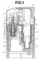
- FIG. 1 is a side view in section of an ignitor for a gas lighter having a filter structure according to one embodiment of the invention, taken on a vertical and longitudinal mid-plane;
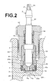
- FIG. 2 is an enlarged cross sectional view showing a valve mechanism portion;
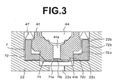
- FIG. 3 is an enlarged cross sectional view showing a filter structure portion.
- a gas lighter 1 (ignitor) of the embodiment comprises a lighter body 2 containing fuel gas; an discharge nozzle 3 having a tip nozzle hole 31 through which the fuel gas flows; a valve mechanism 4 for opening and closing a gas passageway from the lighter body 2 according to displacement of the discharge nozzle; a gas lever 5 for lifting the discharge nozzle 3 to open the valve mechanism 4 when the fuel gas is ignited; an electric spark ignition mechanism 6 for igniting the outflowing gas in response to the ignition operation, a filter component 7 which is placed over an opening formed in the bottom of the valve mechanism 4 to communicate with a tank chamber 24 and which serves to control the gas flow; a cap 8, which is disposed around the upper part of the discharge nozzle 3, and an operation button 9 used for causing the gas supply and ignition.
- the lighter body 2 has a tank body 21 (the lower part thereof is not shown) formed of synthetic resin in a tubular shape having a lower bottomed end.
- An upper lid 22 is hermetically fixed onto the top of the tank body 21.
- a tank chamber 24 for storing therein gaseous fuel such as butane gas is formed within the tank body 21, and an intermediate case 23 is fitted onto the upper lid 22.
- the known valve mechanism 4 to start and stop feeding of the gas to the discharge nozzle 3 vertically extends through the upper lid 22 of the lighter body 2.
- the discharge nozzle 3 having a thin tubular shape is provided about the longitudinal axis of the valve mechanism 4 so as to be axially movable.
- a tip portion of the discharge nozzle 3 extends beyond the upper end of the valve mechanism 4.
- the discharge nozzle 3 comprises a tapered tip portion near the nozzle hole 31; and a neck 32 which is provided directly below the tip portion so as to be stepped to show a decrease of diameter.
- a nozzle engaging portion 51 formed at one end of the gas lever 5 is engaged with the upper end of the neck 32.
- a nozzle tip 34 is fitted in the tip nozzle hole 31 of the discharge nozzle 3 and serves to increase the degree of air mixing by diffusing a part of the gas from the nozzle hole 31 in the peripheral region of the nozzle hole 31 in order to enhance ease of ignition by electric spark ignition to be described layer.
- the valve mechanism 4 is intended to open the gas passageway to permit discharge of the gas from the nozzle.
- This valve mechanism is assembled as follows: the filter component 7 and the valve main body 41 (valve bottom) are fitted in this order into a mounting aperture 22b formed through the upper lid 22, a hold-down member 42 (nozzle screw) is screwed to press the valve main body 41, and the discharge nozzle 3 is disposed in an axially slidable manner within the valve main body 41 and the hold-down member 42.
- a valving element 44 is fitted onto the lower inner end of the discharge nozzle 3 to plug the inner passage thereof, while the inner passage is communicated with the peripheral region through the side opening 33 located at the middle of the nozzle.
- the valve main body 41 has a bottom which has a center hole 41a and therefore serves as a valve seat.
- the valving element 44 is seated thereon and acts to open and close the center hole 41a, whereby feeding of the gas is started and stopped.
- the discharge nozzle 3 is urged downward in its seating direction by a nozzle spring 45 disposed in a compressed state between the discharge nozzle and the upper inner end of the hold-down member 42.
- the central portion of the lower end 41b of the valve main body 41 i.e., a rim around the center hole 41a, extends downward, and a holder 72 of the filter component 7 is fitted therearound.
- a filter 71 affixed to the holder 72 is located below the center hole 41a of the valve main body 41, and communication with the interior of the tank chamber 24 is provided via the filter 71 and the passage hole 22a of the upper lid 22.
- the lighter is intended for delivering the fuel in gas phase and does not have a wick of a porous material. Details on the filter component 7 will be described later.
- An O-ring 47 for hermetically sealing the space between the inner peripheral surface of the mounting aperture 22b of the upper lid 22 and the valve main body 41, is fitted around the periphery of the valve main body 41.
- Another O-ring 48 for hermetically sealing the space between the inner peripheral surface of the hold-down member 42 and the discharge nozzle 3, is fitted around the periphery of the discharge nozzle 3 and in contact with one end of the nozzle spring 45.
- the operation button 9 which is disposed above the lighter body 2 (intermediate case 23) at the opposite end to the discharge nozzle 3, has a tubular bottom attached to the upper end of a piezoelectric device 61 of the ignition mechanism 6 and can be pressed downward.
- the ignition mechanism 6 includes the piezoelectric device 61 whose lower portion is held by the intermediate case 23 and whose upper portion is movable in the vertical direction.
- a spark electrode 62 connected to the upper end of the piezoelectric device 61 is disposed at the upper part of the operation button 9.
- a high voltage, generated by the operation of the piezoelectric device 61, is applied between the spark electrode 62 and the discharge nozzle 3 (nozzle tip 34), whereby an electric spark for ignition is produced.
- Depression of the operation button 9 involves downward movement of the upper half part of the piezoelectric device 61.
- the lever pusher 63 which is brought into contact with the linking portion 53 of the gas lever 5 and causes the gas lever 5 to rotate, is provided in the moving section of the piezoelectric device 61.
- the first depression of the operation button 9 causes the lever pusher 63 to rotate the gas lever 5, thereby causing ejection of the fuel gas through the discharge nozzle 3.
- Further depression of the operation button 9 operates the piezoelectric device 61 to produce a spark ignition.
- the filter component 7 comprises the filter 71 and the holder 72 for fixedly holding the filter 71.
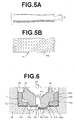
- the filter 71 is, as shown in FIG. 5a, is made by superimposing the membrane film 71a, which has pores and serves to keep the passage rate of the gas flowing through the filter constant, and a gas permeable porous body 71b. Before being welded to the holder 72, the membrane film 71a and the porous body 71b are not joined together.
- the membrane film 71a is formed of, for example, a drawn polypropylene film having pores of a radius ranging from 200 to 5000 nm, and has properties to assure the gas passage at a constant flow rate substantially independently of the amount and temperature of the gas in the tank chamber 24. This controls the flow rate of the gas through the membrane film, whereby the amount of the discharged gas and hence the flame length are kept constant without the need for adjustment.
- the porous body 71b is nonwoven fabric made of synthetic resin.
- the fibers employed in the nonwoven fabric have preferably a fiber diameter within a range between 30 and 15 ⁇ m and a base weight (fiber weight) within a range between 40 and 15 g/m 2 , and are polypropylene fibers formed from the same material as of the membrane film 71a, polyester fibers with a low wettability, or fibers made butanophobic.
- the material of the porous body 71b nonwoven fabric
- polypropylene resin which is the same as of the membrane film 71a
- polyester fibers having a lower wettability than the membrane film 71a are more preferable.
- the ignitors such as a gas lighter 1 in which the gas-phase fuel is controlled, are characterized in that the lower side of the membrane film 71a may be brought into direct contact with the liquefied gaseous fuel when the ignitor is used while the ignitor is tilted.
- the flame length when the liquefied fuel is in contact with the lower side of the membrane film tends to be longer than the flame length when the vaporized fuel is in contact with the lower side of the membrane film.
- our test results revealed that when polyester fibers with a wettability lower than that of polypropylene are used as the material of the porous body 71b (nonwoven fabric) to be superimposed entirely on top of the membrane film 71a, the difference in flame length between the gas-phase combustion state when the ignitor is positioned in a normal position (upright position) and the liquefied gas combustion state when the ignitor is positioned in a tilted position was reduced.
- the direct contact of the low-wettability fibers with the top of the membrane film enables control of the liquefied fuel, without influencing the vaporized fuel.
- the holder 72 comprises a disk portion 72a having a centrally formed vent hole 72c; and a tubular portion 72b provided along the outer periphery of the disk portion 72a.
- the filter 71 is welded to the end face 72d of the disk portion 72a along the peripheral edge of the vent hole 72c. The most stable welded condition is obtained when the holder 72 is made of the same material, polypropylene resin, as of the membrane film 71a.
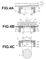
- the filter component 7 is constructed as shown in FIGS. 4A to 4C.
- the sheet type porous body 71b (nonwoven fabric) and the membrane film 71a are layered in this order on the end face 72d of the disk portion 72a of the holder 72 as shown in FIG. 4A.
- a sealer 75 heated to a predetermined temperature is pressed against the filter 71 such that the filter 71 is welded to the peripheral edge of the vent hole 72c in the end face 72d of the disk portion 72a as shown in FIG. 4B.
- the filter 71 is severed at the periphery of the holder 72 to form the filter component 7.
- the membrane film 71a and porous body 71b constituting the filter 71 are not joined together within the vent hole 72c of the holder 72.
- the filter 71 is a multilayer structure which has no joint points between the membrane film 71a and the porous body 71b within the region corresponding to the region within the vent hole. Further, since the membrane 71a and porous body 71b are stamped out of corresponding flat sheet materials after being welded to the resin holder 72, the state of these two films disposed one on top of another is always stable.
- the filter 71 is fusion-bonded at a region except its effective permeable zone to the cylindrical resin holder 72, whereby the fusion-bonded region is resinified to provide a complete seal between the filter 71 and the holder 72. Consequently, gas flow in the radially outward direction toward the outside of the filter is blocked.
- the filter 71 may be affixed to the holder 72 by insert molding to mold the holder 72 with the filter being disposed in position within the mold, as well as by thermal welding and ultrasonic welding.
- Experimental research on welding has shown that welding, by which the permeable zones are kept constant in size, can be achieved by adjusting temperature conditions, time, dimensions of the sealer 75 and resin holder 72, and clearance thereof.
- the filter component 7 is assembled on the upstream side of the valve mechanism 4 as shown in FIGS. 2 and 3.
- the filter component 7 is first inserted into the mounting aperture 22b of the upper lid 22, and then engaged with the valve mechanism 4.
- a part of the valve mechanism 4, that is, the lower end 41b of the valve main body 41, is inserted into the tubular portion 72b of the holder 72, and an O-ring is press-fit onto the upper end of the tubular portion 72b to provide a gas tight seal between the inside and outside of the holder 72.
- the gas passage rate is determined by the size of the vent hole 72c (the area of the membrane film 71a through which the fuel gas can pass).
- the filter component 7 is positioned between the bottom surface 22c of the recessed mounting aperture 22b of the upper lid 22 for sealing the liquefied gas in the tank room 24 and the rubber O-ring 47 fixed around the valve main body 41.
- a hermetic seal across the filter 71 is thus maintained by the upper end face of the resin holder 72 and the O-ring 47.
- the O-ring 47 also serves as a seal between the inner peripheral surface of the mounting aperture 22b and the valve main body 41.
- the resin holder 72, the membrane film 71a and the porous body 71b are fused and resinified to provide complete hermeticity. Therefore, during assembly, care is needed only in sealing the resin holder 72 and the O-ring 47. Reliable hermeticity can be thus maintained without the need for careful press-fit and crimping operations.
- the porous body 71b is positioned closer to the valve mechanism 4, and always in contact with the lower end 41b of the valve main body 41.
- the holder 72 is shaped to surround the valve main body 41 which is a metal component whose inner surface supplies heat in the periphery of the filter 71.
- the membrane film 71a is tensioned via the porous body 71b with the bottom end surface of the lower end 41b of the valve main body 41 being in contact with the porous body 71b of the filter 71.
- This provides a constant stable state of the membrane film 71a without affecting the permeability thereof.
- the metal (for example, brass) valve main body 41 also serves to give heat required for evaporation, the filter 71 can be efficiently supplied with the heat for evaporation by constantly holding the valve main body 41 in contact with the porous body 71b.
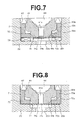
- FIG. 6 is a cross sectional view of the membrane film 71a of the filter 71, illustrating different degrees of tensioning (pressing down) of the membrane film 71a, as the results of height adjustments of the valve main body 41 by the hold-down member 42 (nozzle screw) of the valve mechanism 4.
- the left-hand part of FIG. 6 shows a less tensioned state of the filter 71.
- Our test results revealed that when the filter 71 is further tensioned, as shown in the light-hand part of FIG. 6, from this state, the gas passage rate through the membrane film 71a slightly increases. This is not enough to control the flame length over a broad range, but can give a slight control of the flame length as much as 1 to 5 mm.
- the flame length may optionally be made controllable in the manufacturing process.
- a gas lighter 1 configured as described above will be described in the following.
- the nozzle spring 45 urges the discharge nozzle 3 downward and the valving element 44 is seated in its seat, whereby the center hole 41a is closed to stop feeding of the gas.
- This causes the gas lever 5 to be positioned with the nozzle engaging portion 51 being lowered. Ignition takes place by pressing down the operation button 9 by a finger, so that the piezoelectric device 61 is pressed down and the lever pusher 63 acts to pivot the gas lever 5.
- the discharge nozzle 3 is lifted upward and the valving element 44 moves to open the center hole 41a.
- the fuel gas After leaving the tank chamber 24 and transmitted through the filter 71, the fuel gas, which is kept at a constant flow rate, makes its way along the periphery of the discharge nozzle 3, flows into the internal passage of the nozzle via the opening 33, and is finally emitted from the tip nozzle hole 31.
- the piezoelectric device 61 Immediately following the emission, the piezoelectric device 61 generates a spark to ignite the emitted gas, causing a flame of predetermined length.
- the discharge nozzle 3 is moved downward by the nozzle spring 45 of the valve mechanism 4, whereby emission of the gas is stopped and accordingly the fire is put out, and the gas lever 5 is returned to its original location.
- the operation button 9 is moved upward by a spring incorporated in the piezoelectric device 61, thereby returning to its original location.
- the filter 71 is welded to the holder 72 at its peripheral region, which is a region other than its permeable zone. Therefore, no joint points are present within the permeable zone of the filter 71, and variations in flow rate, which is determined depending on the area of its permeable zone, are minimized. Further, the present filter component 7 is manufactured by welding a filter to an inexpensive resin holder 72, so that handling of the components such as an assembly provided by using a machine is significantly facilitated, and hence the costs associated therewith are reduced.
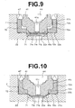
- FIG. 7 shows another embodiment of a filter structure which is similar to that shown in FIG. 3 except that a resilient body 73, which is formed in a shape of a flat ring such that the permeable zone is not obstructed thereby, is placed adjacent to a tank chamber 24 under the filter component 7 and disposed between a disk portion 72a and a bottom surface 22c.
- a resilient body 73 which is formed in a shape of a flat ring such that the permeable zone is not obstructed thereby, is placed adjacent to a tank chamber 24 under the filter component 7 and disposed between a disk portion 72a and a bottom surface 22c.
- placement of the resilient body 73 minimizes the space below the filter 71 where liquid stands, so that uniform burning of the gaseous fuel can be achieved. Further, the load applied onto an upper lid 22 when the hold-down member 42 is screwed can be reduced.
- FIG. 8 is a cross sectional view showing a filter 71 according to another embodiment.
- the filter 71 of this embodiment comprises a membrane film 71a and a porous body 71c superimposed thereon, both of which are constructed of resin mesh material comprising fibers of very small diameter, instead of nonwoven fabric.
- the porous body 71c constructed of the mesh material has more uniform porosity compared with the nonwoven fabric. Accordingly, in the case where the gaseous fuel combustion phase transits to the liquefied fuel combustion phase which occurs when the ignitor such as a gas lighter 1 is used in a tilted position, the flame length can be controlled to be constant more reliably in terms of flow rate. Better control can be provided when the fiber diameter of the mesh material is within a range between about 15 to 30 ⁇ m and the mesh interval width of the material is within a range between about 200 to 500 ⁇ m.
- the porous body 71c constructed of the aforementioned mesh material is also superimposed on the membrane film 71a, and welded to the holder 72 along the periphery of the vent hole 72c thereof as described above.
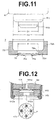
- FIG. 9 is a cross sectional view showing a filter 71 according to still another embodiment.
- the filter 71 of this embodiment has a three layered construction consisting of a membrane film 71a and porous bodies 71b, 71b constructed of nonwoven fabric and respectively placed on opposite sides of the membrane film. Welding the three-layer filter 71 to a holder 72 result in reinforcing the mechanical strength of the membrane film 71a.
- the membrane film 71a typically used in ignitors such as a gas lighter 1 is a film having a pore size of 0.05 ⁇ m and a thickness of approximately 0.02 mm.
- This membrane film 71a is produced by uniaxially drawing polypropylene film and has an orientation tendency. Therefore, the membrane film 71a has the property of being more easily torn in a direction other than a certain direction. Because of this, the film is occasionally broken under a dropping impact or during assembly.
- the mechanical strength of the filter 71 can be reinforced without deteriorating the permeability of the filter by placing the porous bodies 71b, 71b respectively on opposite sides of the membrane film 71a and welding them onto the holder 72.
- FIGS. 10 and 11 are cross sectional views showing a filter structure according to still another embodiment.
- the filter component 7 of the embodiment is substantially same in structure as the embodiment in FIG. 3 which is illustrated together with the filter 71 and the holder 72.
- the difference from the embodiment in FIG. 3 is that an inwardly tapered transition region is provided at the juncture within a holder 72 between a disk portion 72a and a disk portion 72b.
- the filter component 7 is configured such that the inner peripheral surface of the holder 72 is disposed closer to the outer peripheral surface of the lower end 41b of a valve main body 41 of a valve mechanism, whereby a smaller volume is defined between the holder 72 and the valve main body 41. More specifically, as shown in FIG. 11, the inner diameter d1 of a vent hole 72c of the holder 72 and the outer diameter D1 of the lower end 41b of the valve main body 41 to be inserted into the vent hole 72c are dimensioned to permit them to be engaged with each other while maintaining a predetermined fit tolerance (d1 ⁇ D1). When assembled, the inner peripheral surface of the vent hole 72c and the outer peripheral surface of the lower end 41b are brought close to or in contact with each other.
- the inner diameter d2 of the tubular portion 72b of the holder 72 and the outer diameter D2 of a step portion 41c of the valve main body 41 to be inserted in the tubular portion 72b are dimensioned to permit them to engage with each other while maintaining a predetermined fit tolerance (d2 ⁇ D2).
- d2 ⁇ D2 a predetermined fit tolerance
- the inner peripheral surface of the tubular portion 72b and the outer peripheral surface of step portion 41c are brought close to or in contact with each other.
- the valve main body 41 is assembled to the filter component 7, the valve main body 41 is inserted in the filter component, such that the bottom surface and chamfered surface of the step portion 41c of the valve main body 41 are brought close to or in contact with the upper surface and tapered surface the disk portion 72a of the holder 72.
- valve main body 41 may be configured to have dimensions larger than those of the mating component, when the material of the holder 72 is resilient resin.
- the inner peripheral surface of the holder and the outer periphery of the valve body 41 are disposed in close proximity to each other, and therefore gap therebetween is small. Accordingly, the volume defined therebetween is small. As a result, the amount of the liquefied gas retained at the valve mechanism 4 side portion on the filter 71 is minimized, and hence an accidental blaze, which may momentarily occur when the retained gas is supplied at once when the valve is opened, can be prevented.
- this construction permits providing heat supply from the valve main body 41 made of low-thermal-conductivity metal (for example, brass) to the holder 72 and filter 71, restraining heat lost of the filter 71 through evaporation, and maintaining a constant quantity of evaporation, whereby the effect of stabilizing the flame length is produced.
- low-thermal-conductivity metal for example, brass
Landscapes
- Engineering & Computer Science (AREA)
- Chemical & Material Sciences (AREA)
- Combustion & Propulsion (AREA)
- Mechanical Engineering (AREA)
- General Engineering & Computer Science (AREA)
- Lighters Containing Fuel (AREA)
Applications Claiming Priority (3)
| Application Number | Priority Date | Filing Date | Title |
|---|---|---|---|
| JP2002145958A JP3867851B2 (ja) | 2002-05-21 | 2002-05-21 | 着火器のフィルター構造 |
| JP2002145958 | 2002-05-21 | ||
| PCT/JP2003/005978 WO2003098112A1 (fr) | 2002-05-21 | 2003-05-14 | Structure de filtre d'allumeur |
Publications (2)
| Publication Number | Publication Date |
|---|---|
| EP1533570A1 true EP1533570A1 (fr) | 2005-05-25 |
| EP1533570A4 EP1533570A4 (fr) | 2008-05-21 |
Family
ID=29545103
Family Applications (1)
| Application Number | Title | Priority Date | Filing Date |
|---|---|---|---|
| EP03728068A Withdrawn EP1533570A4 (fr) | 2002-05-21 | 2003-05-14 | Structure de filtre d'allumeur |
Country Status (6)
| Country | Link |
|---|---|
| US (1) | US20050175947A1 (fr) |
| EP (1) | EP1533570A4 (fr) |
| JP (1) | JP3867851B2 (fr) |
| CN (1) | CN100385171C (fr) |
| AU (1) | AU2003234801A1 (fr) |
| WO (1) | WO2003098112A1 (fr) |
Cited By (1)
| Publication number | Priority date | Publication date | Assignee | Title |
|---|---|---|---|---|
| WO2014057300A1 (fr) * | 2012-10-12 | 2014-04-17 | SOCIéTé BIC | Ensemble de valve pour un briquet à gaz |
Families Citing this family (9)
| Publication number | Priority date | Publication date | Assignee | Title |
|---|---|---|---|---|
| US20060003280A1 (en) * | 2003-06-03 | 2006-01-05 | The Japan Smoking Articles Corporate Association | Hydrocarbon gas flow rate adjusting method and apparatus |
| DE102005005283A1 (de) * | 2005-02-04 | 2006-08-17 | Siemens Ag | Maschinenanlage mit Thermosyphon-Kühlung ihrer supraleitenden Rotorwicklung |
| CN101074781B (zh) * | 2006-05-19 | 2010-09-01 | 黄逢竞 | 打火机气阀门用免调节限流装置 |
| JP4849956B2 (ja) * | 2006-05-22 | 2012-01-11 | 株式会社東海 | 着火器 |
| KR101308163B1 (ko) | 2006-06-30 | 2013-09-12 | 엘지디스플레이 주식회사 | 표시장치의 화소 전극 구조 |
| KR101056493B1 (ko) * | 2009-05-08 | 2011-08-12 | 이기철 | 가스 라이터 |
| CN104279578A (zh) * | 2013-07-06 | 2015-01-14 | 阴运和 | 稳压片 |
| CN110584219B (zh) * | 2019-10-15 | 2024-09-03 | 中国科学技术大学先进技术研究院 | 燃料流量调节装置和加热不燃烧型烟草制品 |
| CN110604343B (zh) * | 2019-10-15 | 2024-06-11 | 中国科学技术大学先进技术研究院 | 一种抽吸装置 |
Citations (4)
| Publication number | Priority date | Publication date | Assignee | Title |
|---|---|---|---|---|
| US4478570A (en) * | 1980-09-05 | 1984-10-23 | Feudor S.A. | Flow control device for disposable gas lighter |
| US4906179A (en) * | 1988-07-01 | 1990-03-06 | Tokai Corporation | Inner combustion type of gaslighter |
| US4929175A (en) * | 1988-04-27 | 1990-05-29 | Tokai Corporation | Noncontrolling type valve |
| US5490777A (en) * | 1993-09-27 | 1996-02-13 | Fujiwara Industrial Co., Ltd. | Fuel gas supply adjuster |
Family Cites Families (7)
| Publication number | Priority date | Publication date | Assignee | Title |
|---|---|---|---|---|
| US447857A (en) * | 1891-03-10 | Galvanic apparatus for the human body | ||
| US456034A (en) * | 1891-07-14 | Shade or globe holder | ||
| US3663152A (en) * | 1968-10-25 | 1972-05-16 | Zenza Bronica Kogyo Kk | Automatic flame adjusting means in a lighter |
| FR2313638A1 (fr) * | 1975-06-05 | 1976-12-31 | Genoud & Cie Ets | Detendeur pour briquet a gaz |
| AT371583B (de) * | 1980-11-24 | 1983-07-11 | Schaechter Friedrich | Einrichtung zur konstanthaltung der flammengroesse eines mit fluessiggas betriebenen kleinbrenners, vorzugsweise eines feuerzeugbrenners |
| JPH0412356Y2 (fr) * | 1988-07-01 | 1992-03-25 | ||
| JPH0335969Y2 (fr) * | 1988-04-27 | 1991-07-30 |
-
2002
- 2002-05-21 JP JP2002145958A patent/JP3867851B2/ja not_active Expired - Fee Related
-
2003
- 2003-04-15 US US10/514,203 patent/US20050175947A1/en not_active Abandoned
- 2003-05-14 EP EP03728068A patent/EP1533570A4/fr not_active Withdrawn
- 2003-05-14 WO PCT/JP2003/005978 patent/WO2003098112A1/fr active Application Filing
- 2003-05-14 CN CNB038115743A patent/CN100385171C/zh not_active Expired - Fee Related
- 2003-05-14 AU AU2003234801A patent/AU2003234801A1/en not_active Abandoned
Patent Citations (4)
| Publication number | Priority date | Publication date | Assignee | Title |
|---|---|---|---|---|
| US4478570A (en) * | 1980-09-05 | 1984-10-23 | Feudor S.A. | Flow control device for disposable gas lighter |
| US4929175A (en) * | 1988-04-27 | 1990-05-29 | Tokai Corporation | Noncontrolling type valve |
| US4906179A (en) * | 1988-07-01 | 1990-03-06 | Tokai Corporation | Inner combustion type of gaslighter |
| US5490777A (en) * | 1993-09-27 | 1996-02-13 | Fujiwara Industrial Co., Ltd. | Fuel gas supply adjuster |
Non-Patent Citations (1)
| Title |
|---|
| See also references of WO03098112A1 * |
Cited By (2)
| Publication number | Priority date | Publication date | Assignee | Title |
|---|---|---|---|---|
| WO2014057300A1 (fr) * | 2012-10-12 | 2014-04-17 | SOCIéTé BIC | Ensemble de valve pour un briquet à gaz |
| US10215409B2 (en) | 2012-10-12 | 2019-02-26 | SOCIéTé BIC | Valve assembly for a gas lighter |
Also Published As
| Publication number | Publication date |
|---|---|
| US20050175947A1 (en) | 2005-08-11 |
| EP1533570A4 (fr) | 2008-05-21 |
| JP3867851B2 (ja) | 2007-01-17 |
| JP2003336840A (ja) | 2003-11-28 |
| WO2003098112A1 (fr) | 2003-11-27 |
| AU2003234801A1 (en) | 2003-12-02 |
| CN1656342A (zh) | 2005-08-17 |
| CN100385171C (zh) | 2008-04-30 |
Similar Documents
| Publication | Publication Date | Title |
|---|---|---|
| EP1533570A1 (fr) | Structure de filtre d'allumeur | |
| JPS6350613B2 (fr) | ||
| US3860385A (en) | Cigarette lighter | |
| US5083916A (en) | Fuel combustion apparatus and method | |
| KR20000029459A (ko) | 액체연료용연소기구 | |
| JPH0335969Y2 (fr) | ||
| WO2001018452A1 (fr) | Allumoir a gaz et dispositif d'ejection de combustible de cet allumoir | |
| JP4849956B2 (ja) | 着火器 | |
| US4746288A (en) | Compact cartridge lighter having fuel vaporization element in combination with liquid barrier filter | |
| JP5389421B2 (ja) | ガスライターの燃料吐出流量調整装置 | |
| US5490777A (en) | Fuel gas supply adjuster | |
| JPS63238331A (ja) | ガスライタ−用フイルタ装置 | |
| US6938498B2 (en) | Hydrocarbon gas flow rate adjusting method and apparatus | |
| US3592579A (en) | Lighter using liquefied gas as fuel | |
| EP0870984A1 (fr) | Appareil de combustion pour combustible liquide | |
| JPS58145823A (ja) | ガスライタ | |
| US20040152030A1 (en) | Gas lighter | |
| JPH05180359A (ja) | 液化石油ガス等の流量制限装置 | |
| US6102688A (en) | Combustion apparatus for liquid fuel and combustion wick | |
| JPS61119917A (ja) | 使い棄て巻きたばこライター | |
| KR101056493B1 (ko) | 가스 라이터 | |
| JPH0412357Y2 (fr) | ||
| JPH01150718A (ja) | ガスライタ | |
| JPH06101837A (ja) | ガスライターの炎長調整装置 | |
| JP2802905B2 (ja) | ガスライターのバーナー装置 |
Legal Events
| Date | Code | Title | Description |
|---|---|---|---|
| PUAI | Public reference made under article 153(3) epc to a published international application that has entered the european phase |
Free format text: ORIGINAL CODE: 0009012 |
|
| 17P | Request for examination filed |
Effective date: 20041215 |
|
| AK | Designated contracting states |
Kind code of ref document: A1 Designated state(s): AT BE BG CH CY CZ DE DK EE ES FI FR GB GR HU IE IT LI LU MC NL PT RO SE SI SK TR |
|
| RBV | Designated contracting states (corrected) |
Designated state(s): DE ES FR GB NL |
|
| A4 | Supplementary search report drawn up and despatched |
Effective date: 20080421 |
|
| RIC1 | Information provided on ipc code assigned before grant |
Ipc: F23Q 2/28 20060101ALI20080415BHEP Ipc: F23Q 2/34 20060101ALI20080415BHEP Ipc: F23Q 2/173 20060101AFI20080415BHEP |
|
| 17Q | First examination report despatched |
Effective date: 20091214 |
|
| STAA | Information on the status of an ep patent application or granted ep patent |
Free format text: STATUS: THE APPLICATION IS DEEMED TO BE WITHDRAWN |
|
| 18D | Application deemed to be withdrawn |
Effective date: 20100427 |