EP1533568B1 - Hochtemperatur-Ofen - Google Patents
Hochtemperatur-Ofen Download PDFInfo
- Publication number
- EP1533568B1 EP1533568B1 EP03405819A EP03405819A EP1533568B1 EP 1533568 B1 EP1533568 B1 EP 1533568B1 EP 03405819 A EP03405819 A EP 03405819A EP 03405819 A EP03405819 A EP 03405819A EP 1533568 B1 EP1533568 B1 EP 1533568B1
- Authority
- EP
- European Patent Office
- Prior art keywords
- furnace
- filling
- high temperature
- opening
- tapping
- Prior art date
- Legal status (The legal status is an assumption and is not a legal conclusion. Google has not performed a legal analysis and makes no representation as to the accuracy of the status listed.)
- Expired - Lifetime
Links
Images


Classifications
-
- F—MECHANICAL ENGINEERING; LIGHTING; HEATING; WEAPONS; BLASTING
- F23—COMBUSTION APPARATUS; COMBUSTION PROCESSES
- F23G—CREMATION FURNACES; CONSUMING WASTE PRODUCTS BY COMBUSTION
- F23G5/00—Incineration of waste; Incinerator constructions; Details, accessories or control therefor
- F23G5/08—Incineration of waste; Incinerator constructions; Details, accessories or control therefor having supplementary heating
- F23G5/085—High-temperature heating means, e.g. plasma, for partly melting the waste
-
- F—MECHANICAL ENGINEERING; LIGHTING; HEATING; WEAPONS; BLASTING
- F23—COMBUSTION APPARATUS; COMBUSTION PROCESSES
- F23G—CREMATION FURNACES; CONSUMING WASTE PRODUCTS BY COMBUSTION
- F23G5/00—Incineration of waste; Incinerator constructions; Details, accessories or control therefor
- F23G5/20—Incineration of waste; Incinerator constructions; Details, accessories or control therefor having rotating or oscillating drums
-
- F—MECHANICAL ENGINEERING; LIGHTING; HEATING; WEAPONS; BLASTING
- F23—COMBUSTION APPARATUS; COMBUSTION PROCESSES
- F23J—REMOVAL OR TREATMENT OF COMBUSTION PRODUCTS OR COMBUSTION RESIDUES; FLUES
- F23J1/00—Removing ash, clinker, or slag from combustion chambers
- F23J1/02—Apparatus for removing ash, clinker, or slag from ash-pits, e.g. by employing trucks or conveyors, by employing suction devices
-
- F—MECHANICAL ENGINEERING; LIGHTING; HEATING; WEAPONS; BLASTING
- F23—COMBUSTION APPARATUS; COMBUSTION PROCESSES
- F23G—CREMATION FURNACES; CONSUMING WASTE PRODUCTS BY COMBUSTION
- F23G2203/00—Furnace arrangements
- F23G2203/20—Rotary drum furnace
- F23G2203/202—Rotary drum furnace rotating around substantially vertical axis
Definitions
- the invention relates to a high-temperature furnace for burning and melting waste and a method for operating such a high-temperature furnace having the features of the preamble of the independent claims.
- Problematic waste such as toxic or radioactive waste
- furnace types There are different furnace types, such.
- induction furnaces electric arc furnaces or plasma ovens for the treatment of toxic and / or radioactive waste known.
- the inert atmosphere in the plasma furnace and the high arc temperatures of 10000 ° C to 15000 ° C lead to a complete decomposition of the materials to be treated. Solid residues of these materials can in turn be fixed in a glass matrix and thus encapsulated in the environment.
- Generically known rotary hearth furnaces are operated at such a rotational speed that due to the centrifugal force the liquefied furnace filling collects in the outer area of the furnace bottom and the casting opening remains free.
- the furnace bottom lining is not completely covered with melt and thus exposed directly to the high arc temperatures of 10'000 to 15'000 ° C of the plasma torch.
- the furnace bottom substructure and supporting structure of the cast stone shown in EP 0 636 839 B1 must be actively cooled.
- it has been shown that during operation of the furnace cooling is relatively difficult and that the furnace bottom lining is exposed to high thermal loads, in particular in the region of the casting openings. This leads to a relatively short life of the furnace bottom lining, frequent renewal of the furnace lining are the result.
- the oven should be able to operate more efficiently, easily and safely.
- the inventive high-temperature furnace for burning and melting of particular radioactive waste contains at least one plasma torch arranged in the furnace and a centrifuge rotatable about a rotation axis.
- the centrifuge which has a furnace trough with furnace bottom and furnace side wall, has a casting opening arranged in the furnace bottom, in the axis of rotation.
- the furnace is characterized in that a filling device is provided for filling the casting opening with, in particular, high-temperature-resistant filling sand. Due to the backfill sand filling of the casting opening, the rotational speed of the centrifuge can be set so low that the melt covers the entire furnace bottom, not just its edge area. The bottom of the oven is completely covered and protected against overheating.
- molten Good consisting of glass and residues of treated waste such as concrete, ion exchange resins, as well as plastics and metals of all kinds, etc.
- the required for the operation of the furnace energy is introduced through the plasma torch.
- temperatures of 10'000 ° to 15'000 ° Celsius are achieved.
- the oven is ideally suited for the decomposition, incineration and / or smelting of radioactive, highly toxic or other problematic wastes due to the locally achievable high temperatures and the inert atmosphere.
- the furnace bottom has electrically conductive features.
- graphite bricks or electrically conductive, thermally resistant ramming masses can be used in the furnace bottom.
- the necessary electrical current flow can also be ensured via a conductive ring in the region of the casting opening become.
- a plurality of elongated electrodes disposed within a thermally and chemically resistant lining material may be employed.
- the furnace bottom lining must, in particular, be thermally and chemically resistant.
- a backfill filled with fill sand has several advantages.
- the rotary hearth furnace since the furnace bottom and thus the furnace bottom lining is completely covered, can be operated at a relatively low rotational speed.
- the service life is increased and the risk of a furnace breakthrough is reduced. This allows more efficient operation and in particular improves the introduction of energy into the furnace.
- the casting opening has a closing element for retaining the filling sand.
- a casting opening is preferably designed as a channel running in the axis of rotation of the centrifuge. Before the introduction of the backfill sand, the lower end of the channel can be shut off by a closing element.
- the closing element rotates together with the furnace bottom about its own axis and is preferably attached to a lifting / pivoting arm, which in turn is hinged to the furnace structure. Due to the chemical composition of the backfill sand and its physical properties can be ensured that the filling sand remains in the casting channel.
- the filling device has a filling profile, in particular a pipe.
- a filling profile in particular a pipe.
- Such a filling profile can be movably connected to the filling device such that the filling profile can be brought directly to the casting opening, whereby a secure and accurate filling is possible.
- the filling device is arranged on the top of the furnace. This has the advantage that pourable filling sand can be brought into the casting opening or the casting channel by mere utilization of the gravitational force. Under certain circumstances supportive devices for shaking or vibrating can be taken to help, whereby the filler sand to be filled becomes more fluid.
- the filling device but at least the filling profile is arranged in the axis of rotation of the furnace. This allows the backfill sand to be filled safely into the casting channel.
- the furnace has a cleaning device with the aid of which at least a part of the backfill sand can be removed from the casting opening.
- a cleaning device With the help of the cleaning device, an opening for casting melt can be created. This ensures in particular that the melt can be poured safely and controlled.
- the cleaning device has a lance movable along the axis of rotation, the tip of which is in the casting opening is insertable.
- the lance is preferably rotationally symmetrical, wherein the diameter of the lance tip is equal to or smaller than the diameter of the Abgussssö réelle.
- the lance is arranged in a starting point outside the interior of the furnace. In this case, the lance is only for the cleaning process in the interior of the furnace, whereby the lance must be exposed only relatively short to the prevailing high thermal loads.
- the arrangement of the lance along the axis of rotation has the advantage that the backfill sand can be accurately removed from the casting channel.
- Another aspect of the invention relates to a method for decomposing, burning and melting waste, in particular radioactive waste in a high-temperature furnace (rotary hearth furnace).
- the rotary hearth furnace has at least one plasma torch arranged therein, a centrifuge rotatable about an axis of rotation and a casting opening arranged in the furnace bottom of the centrifuge in the axis of rotation.
- the method consists of the following steps: Closing of the pouring channel by filling sand, introduction of combustible and / or fusible material such as concrete, ion exchange resins, as well as plastics and metals of all kinds, etc.
- filling sand is thus introduced into a preferably channel-like casting opening.
- the filling device has a metering device for proper filling with filling sand.
- just so much backfill sand is filled that the entire casting channel is completely filled. But it is also conceivable that more backfill sand is introduced, which an approximately hill-shaped filling sand pile arises in the furnace floor.
- meltable and combustible waste can be introduced into the rotary hearth furnace and treated. Wherein the waste is preferably burned under inert atmosphere at high temperatures by means of the plasma torch and remaining solid particles are included in the melt.
- the centrifuge of the rotary hearth furnace is rotated at a predeterminable rotational speed. Due to the backfilling closed with filling sand, the rotational speed can be chosen so low that the bottom of the furnace remains completely covered by molten material.
- the pouring opening is first closed by means of a closing element. Thereafter, the casting opening or the casting channel is filled with filling sand.
- the closing element ensures on the one hand the retention of the backfill sand in the casting channel, on the other hand it prevents inadvertent outflow of filling sand during operation. Only after the closing element is opened is the filling sand removed from the pouring opening.
- the closing element rotates about its own axis and is preferably attached to a lifting / pivoting arm which in turn is hinged to the furnace structure. For the function "pouring channel closed”, the closing element can be held in position with spring force. For the function "open pouring channel”, the closing element can be swiveled away hydraulically.
- the pouring opening is emptied for emptying the reactor by opening the closing element arranged below the pouring channel and then at least partially removing the filling sand in the pouring channel with the aid of an ejecting or cleaning device. After opening the closing element is under In some circumstances, some of the free-flowing filling sand will flow out of the casting channel. The rotational speed of the rotary hearth furnace is increased such that the casting opening is no longer covered by melt due to centrifugal action. Then with the aid of the ejection or cleaning device, the filling sand is removed from the casting opening.
- the remaining in the pouring channel Verhellsandresten be ejected.
- the rotational speed of the rotary hearth furnace is reduced again. A controlled pouring of molten material can be ensured.
- the outflow speed of the melt can be controlled. The outflowing melt is then collected in a mold and cooled.
- residues of the melt residue are removed from the casting channel with the aid of the cleaning device in such a way that at least some residues of melt residue remain in the casting opening and cover the wall thereof.
- a lance with a diameter smaller than the casting channel diameter removes only melt residue in the region of the center of the casting channel.
- What remains is a plan-shaped annular lining, which is arranged in the casting channel along the axis of rotation and solidifies in a row. This creates a relatively firm and well connected to the casting channel protective layer. The thus calibrated casting channel is thus efficiently protected against wear.
- a further aspect of the invention relates to a method in which molten-material residues are removed only in the center of the casting opening in such a way that molten-material residues remain as cladding or casing in the casting channel. This makes it possible to operate the furnace or the rotary hearth furnace with an open casting channel.
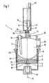
- a furnace designated 1 is shown.
- the furnace 1 has a housing 23 in which a centrifuge 3 rotatable about an axis of rotation R is arranged. Via an opening 24, a plasma torch 2 in the interior 16 of the furnace 1 is arranged.
- the housing 23 has an opening 19 for pyrolysis gas and an opening 18 for filling the furnace with combustible and meltable material and / or waste.
- the opening 18 may be designed such that whole barrels of combustible and meltable material and / or waste, in particular with radioactive or toxic content in the interior 16 of the furnace 1 can be introduced.
- Not shown in FIG. 1 are further possible openings for auxiliary burners, measuring instruments and other devices.
- the centrifuge 3 forms a furnace trough 4 for receiving solid and / or liquid material.
- the furnace tub 4 has a furnace bottom 5 and a furnace side wall 6.
- the furnace bottom 5 is designed in such a way that it can serve for the current guidance originating from the plasma torch 2.
- the furnace bottom 5 can be equipped, for example, with graphite bricks or electrically conductive ramming masses. However, the furnace bottom 5 can also be designed with electrodes for current guidance and with lining materials which have thermally and chemically resistant properties. (see below Figures 3 and 4).
- In the middle of the furnace bottom 5 there is a casting opening 8.
- the casting opening 8 is configured as a channel 25 extending in the direction of the axis of rotation R.
- the casting channel 25 is preferably cylindrical, but convex or concave embodiments are conceivable. Conical insertion areas for a cylindrical channel are also conceivable.
- the lower end of the casting channel 25 or the furnace bottom 5 closes a closing element 7.
- the casting channel 25 is filled with high-temperature-resistant backfill sand 10, for example, a metal oxide-graphite mixture. Suitable, for example, is a backfill sand consisting of a mixture of SiO 2 , Cr 2 O 3 , Al 2 O 3 , Fe 2 O 3 MgO, Cao and C.
- the casting channel 25 is filled completely with backfill sand 10.
- the melt 21 consisting of molten material and embedded therein solids. As can be seen from FIG. 1, the area above the casting opening 8 can be covered with melt 21 thanks to the backfilling with filler sand 10.
- a filling device 9 for filling the filling sand into the casting channel 25.
- the filling sand is led from a storage tank 22 or by means of other feed devices to a filling profile 11.
- the filling profile 11 is preferably configured as a tube and arranged in the axis of rotation R. Flowable filling sand falls through the interior 16 of the furnace onto the casting opening 8 or into the casting channel 25. However, it is also conceivable that the filling profile 11 can be guided to or at least close to the casting opening 8 for filling.
- a cleaning device 13 for clearing the pouring channel 25 from the backfilling sand 10 is further provided in the axis of rotation R.
- the cleaning device 13 has an extendable lance 14, which is arranged in its initial position during operation of the furnace 1 outside the interior 16 of the furnace.
- the interior 16 of the furnace 1 is sealed.
- the furnace is preferably under a negative pressure of 10 to 25 mbar. So that the filling and cleaning device is not thermally stressed during normal operation, the opening 26 is closed. This can be done with a Slider 20, which is displaceable in the x direction happen.
- the filling device 9 on the one hand and the cleaning device 13 on the other hand have different openings instead of an opening 26.
- FIG. 2 shows the oven 1 with the lance 14 extended.
- a slide 20 or another closing device is brought into the open position.
- the lance 14 is moved along the axis of rotation R against the casting opening 8, at least to the extent that the casting channel 25 is pierced over its entire length.
- the tip 15 of the lance 14 is preferably symmetrically aligned.
- the diameter of the tip 15 may correspond to the diameter of the casting opening 8, in particular of the casting channel 25. However, it may be advantageous if the diameter of the tip 15 is smaller than that of the casting channel 8.
- a mold 17 is provided below the casting opening 8.
- the lance 14 or at least the lance tip 15 is made of high-temperature-resistant material, for example, the HAYNES 230 known in the art.
- the lance tip may be formed as a blunt cone.
- the cleaning device 13 may be configured such that it can also serve as a filling device 9.
- a basically hollow lance can be used to fill the pouring channel 25.
- the cleaning device 13, in particular the lance 14 is used to compress the filling sand after filling into the casting opening 8 or into the casting channel 25 by pressing.
- the tip 15 of the lance 14 have a special, in particular flat attachment for pressing the backfill sand.
- the centrifuge 3 shown in FIG. 3 has a lining 28, which is arranged in a preferably metallic support structure 27.
- the lining 28 may consist of common lining materials such as casting and ramming masses or of cast or pressed shaped blocks of corundum, chrome corundum and high-alumina products.
- a cast stone 29 which forms the casting opening 8.
- At least a portion of the furnace bottom interior 30 has a preferably relatively small slope towards the center. The gradient is intended to ensure, in particular, a facilitated discharge of the melt.
- the cast stone 29 is configured horizontally on its side facing the interior 16. A gradient to the middle, however, is also conceivable here.
- an electrically conductive ring element 31 for the current flow, originating from the plasma torch, is arranged. Down closes the casting opening 8 and the casting channel 25 a closing element 7, which is pressed by spring force on the casting stone 29.
- the closing element rotates about its own axis and is preferably attached to a lifting / pivoting arm, which in turn is hinged to the furnace structure.
- the closing element can be held in position with spring force.
- the closing element can be swiveled away hydraulically.
- FIG. 4 shows a rotary hearth furnace or its centrifuge 3 with a drive arrangement 32 for rotating the centrifuge 3 about the axis of rotation R.
- the centrifuge 3 With the aid of a rotary drive, the centrifuge 3 is set in rotary motion via a sprocket. Let ⁇ be the rotation speed.
- the liner 28 has several stabilizing and insulating layers 33 to 35.
- the furnace bottom 5 has a plurality of elongated electrodes 36. These are slightly inclined to the furnace bottom inside 30. In the plan view, the electrodes 36 are uniformly distributed and arranged concentrically to each other. The electrodes 36 are in electrical contact with current collector brushes 37.
- the casting opening 8 is arranged in the axis of rotation of the centrifuge 3.
- FIG. 5 shows a construction (38) containing a filling device 9 and a cleaning device 13.
- the construction 38 is connected to the furnace 1, for example by means of a flange connection 39.
- the structures 38 has a housing 40, in which the cleaning device 13 and the filling device 9 are arranged.
- the extendable lance 14 can be moved along the axis of rotation R with a combination of a spindle drive 41 and a hydraulic cylinder 42. With the help of the spindle drive 41, a part of the distance for the lance 14 is determined.
- a parallel to the rotation axis R extending spindle 44 is rotatably mounted at their ends and is preferably driven by an electric motor. The return of the other route of the lance 14 follows hydraulically.
- the hydraulic drive has the advantage, for example, that a greater force can be applied to pierce the lance of the casting channel 25 charged with filling sand.
- the lance 14 can be guided, for example, along a guide 45, which runs parallel to the axis of rotation R, via a guide carriage 43.
- the cleaning device 13 has an elongated, tubular sheath 46, which serves, for example, a part of the lance 14, in particular when the lance is in the interior 16 of the furnace 1, protects against thermal influences.
- the filling device 9 has at least one reservoir 22 and tubular conduits 47 for guiding the backfill sand, these running approximately at least partially along the lance 14.
- Figures 6 to 9 show - schematically illustrated - a procedure for operating the inventive furnace 1.
- combustible and meltable material Before filling the furnace 1 with combustible and meltable material is in a first step with the aid of the closing element 7 of the pouring channel 25 of the casting opening 8 on the closed bottom side.
- backfill sand can be filled into the prepared casting channel 25.
- the filling sand filling 10 can be pressed or compacted depending on the intended operating mode (FIG. 6).
- glass and combustible and meltable waste such as concrete, ion exchange resins, as well as plastics and metals of all kinds, etc. are introduced into the rotating centrifuge 3.
- the meltable material is melted until a certain Ofen spallgrad is achieved.
- FIG. 7 shows the furnace 1 in normal operation. This rotates at a rotational speed ⁇ 1 .
- the rotational speed ⁇ 1 is preferably to be selected so that the furnace bottom and in particular the casting opening 8 is at least covered. Waste continuously or discontinuously decomposed, incinerated and / or melted down. Resulting combustion and pyrolysis gases are discharged, the remaining solid residues go into the melt 21. If the melt reaches a maximum or another predetermined Ofenhellungsgrad, the melt must be poured from the furnace 1. For this purpose, the rotational speed ⁇ 2 is increased to such an extent that, as a result of the centrifugal force, at least the casting opening 8 is completely freed from melt 21.
Landscapes
- Engineering & Computer Science (AREA)
- Mechanical Engineering (AREA)
- General Engineering & Computer Science (AREA)
- Physics & Mathematics (AREA)
- Plasma & Fusion (AREA)
- Gasification And Melting Of Waste (AREA)
- Processing Of Solid Wastes (AREA)
- Centrifugal Separators (AREA)
- Vertical, Hearth, Or Arc Furnaces (AREA)
Description
- Die Erfindung betrifft einen Hochtemperatur-Ofen zum Verbrennen und Einschmelzen von Abfall und ein Verfahren zum Betreiben eines solchen Hochtemperatur-Ofens mit den Merkmalen des Oberbegriffs der unabhängigen Ansprüche.
- Problematische Abfälle, wie toxische oder radioaktive Abfälle, müssen für eine sichere Beseitigung in Hochtemperatur-Ofen zersetzt und/oder eingeschmolzen werden. Es sind verschiedene Ofentypen, wie z. B. Induktionsöfen, Lichtbogenöfen oder Plasmaöfen für die Behandlung toxischer und/oder radioaktiver Abfälle bekannt. Besonders die inerte Atmosphäre im Plasmaofen sowie die hohen Lichtbogen-Temperaturen von 10000°C bis 15000°C führen zu einer vollständigen Zersetzung der zu behandelnden Materialien. Feste Rückstände dieser Materialien können wiederum in einer Glasmatrix fixiert und so gegenüber der Umwelt verkapselt werden.
- Es sind bereits zahlreiche Hochtemperatur-Öfen, welche mit einem Plasmabrenner als Energiequelle ausgestattet sind, bekannt und gebräuchlich. So beschreiben beispielsweise die EP 0 636 839 B1 und die US-A1-5 005 494 einen Plasma-Drehherdofen. Durch einen transferierenden Plasmabrenner wird die zur Zersetzung des Abfalls erforderliche Energie zugeführt. Die zylinderförmige Ofenkammer (Zentrifuge) des Drehherdofens weist eine in der Rotationsachse gelegene, zentrale Abgussöffnung für das Abgiessen der behandelten, resp. zerzetzten und eingeschmolzenen Abfälle auf. Im Ofenboden sowie in den Seitenwänden ist feuerfestes Material angeordnet.
- Gattungsmässig bekannte Drehherdöfen werden mit einer solchen Drehgeschwindigkeit betrieben, dass sich aufgrund der Zentrifugalkraft die verflüssigte Ofenfüllung im äusseren Bereich des Ofenbodens sammelt und die Abgussöffnung frei bleibt.
- Problematisch ist dabei, dass die Ofenboden-Ausmauerung nicht vollständig mit Schmelzgut bedeckt und somit direkt den hohen Lichtbogentemperaturen von 10'000 bis 15'000° C des Plasmabrenners ausgesetzt ist. So muss etwa die in EP 0 636 839 B1 gezeigte Ofenboden-Unterkonstruktion und Stützkonstruktion des Abgussteines aktiv gekühlt werden. In der Praxis hat sich jedoch gezeigt, dass im Betrieb des Ofens die Kühlung relativ schwierig ist und dass die Ofenboden-Ausmauerung insbesondere im Bereich der Abgussöffnungen zu hohen thermischen Belastungen ausgesetzt ist. Dies führt zu einer verhältnismässig geringen Lebensdauer der Ofenboden-Ausmauerung, häufige Erneuerungen der Ofenauskleidung sind die Folge. Im Weiteren besteht auch die Gefahr, dass unkontrolliert Schmelzgut in die Abgussöffnung fliesst und erstarrt, resp. der Abgusskanal dadurch verstopft werden kann. Ein unbeabsichtigtes oder unkontrolliertes Ausfliessen des Schmelzgutes bei Betriebsstörungen an den Drehantrieben der Zentrifuge ist ebenfalls möglich. Desweiteren zeigt sich in der Praxis, dass sich das aufgrund der Zentrifugalkraft am äusseren Ofenbodendurchmesser ansammelnde Schmelzgut nicht befriedigend homogen aufschmelzen lässt.
- Es ist deshalb eine Aufgabe der vorliegenden Erfindung, die Nachteile des Bekannten zu vermeiden, insbesondere eine Vorrichtung und ein Verfahren der eingangs genannten Art zu schaffen, welche sich durch einen verbesserten Schutz insbesondere der Ofenboden-Ausmauerung und des Abgusssteines und eine höhere Lebensdauer auszeichnet. Der Ofen soll effizienter, einfacher und sicherer betrieben werden können.
- Erfindungsgemäss werden diese Aufgaben mit einem Hochtemperatur-Ofen mit den Merkmalen des kennzeichnenden Teils der unabhängigen Ansprüche gelöst.
- Der erfindungsgemässe Hochtemperatur-Ofen zum Verbrennen und Einschmelzen von insbesondere radioaktiven Abfall enthält wenigstens einen im Ofen angeordneten Plasmabrenner und ein um eine Rotationsachse drehbare Zentrifuge. Die Zentrifuge, die eine Ofenwanne mit Ofenboden und Ofenseitenwand aufweist, verfügt über eine im Ofenboden, in der Rotationsachse angeordnete Abgussöffnung. Der Ofen kennzeichnet sich dadurch aus, dass eine Verfüllvorrichtung zum Füllen der Abgussöffnung mit insbesondere hochtemperatur-beständigem Verfüllsand vorgesehen ist. Durch die Verfüllsand-Verfüllung der Abgussöffnung kann die Drehgeschwindigkeit der Zentrifuge so niedrig eingestellt werden, dass das Schmelzgut den gesamten Ofenboden bedeckt und nicht nur dessen Randbereich. Der Ofenboden wird vollständig abgedeckt und vor Überhitzung geschützt. In der Ofenwanne befindet sich im Normalbetrieb geschmolzenes Gut, bestehend aus Glas und Rückständen der behandelten Abfällen wie Beton, Ionentauscherharzen, sowie Kunstoffe und Metalle aller Arten, usw. Die für den Betrieb des Ofens erforderliche Energie wird über den Plasmabrenner eingebracht. Im unmittelbaren Bereich des Plasmabrenners werden Temperaturen von 10'000° bis 15'000° Celsius erzielt. Der Ofen eignet sich aufgrund der örtlich erzielbaren hohen Temperaturen sowie der inerten Atmosphäre ideal für das Zersetzen, Verbrennen und oder Einschmelzen von radioaktiven, hoch toxischen oder anderen problematischen Abfällen. Für eine Lichtbogen-Plasmaerzeugung weist der Ofenboden elektrisch leitende Merkmale auf. Dazu können im Ofenboden Grafit-Steine oder elektrischleitende, thermisch resistente Stampfmassen eingesetzt werden. Der notwendige elektrische Stromfluss kann jedoch auch über einen leitenden Ring im Bereich der Abgussöffnung gewährleistet werden. Es können auch eine Mehrzahl von länglichen Elektroden, welche innerhalb eines thermisch und chemisch widerstandsfähigen Ausmauerungsmaterial angeordnet sind, eingesetzt werden. Die Ofenboden-Ausmauerung muss im weiteren insbesondere thermisch und chemisch widerstandsfähig sein.
- Eine mit Verfüllsand gefüllte Abgussöffnung hat verschiedene Vorteile. So kann der Drehherdofen, da der Ofenboden und damit die Ofenboden-Ausmauerung vollständig bedeckbar ist, mit einer verhältnismässig geringen Drehgeschwindigkeit betrieben werden. Durch die Bedeckung der Ofenboden-Ausmauerung mit Schmelzgut wird die Standzeit erhöht und das Risiko eines Ofendurchbruchs verringert. Dies ermöglicht einen effizienteren Betrieb und verbessert insbesondere das Einbringen der Energie in den Ofen.
- Durch die Verfüllsandfüllung im Abgusskanal wird ein Verstopfen der Abgussöffnung verhindert. Ausserdem wird ein unbeabsichtigter, unkontrollierter Abguss vermieden. Bei einem Drehherdofen mit offener Abgussöffnung der Zentrifuge kann beim Abfall der Zentrifugen-Drehgeschwindigkeit das Schmelzgut unerwünscht ausfliessen.
- In einer ersten Ausführungsform weist die Abgussöffnung ein Schliesselement zum Rückhalten des Verfüllsandes auf. Eine Abgussöffnung ist vorzugsweise als in der Rotationsachse der Zentrifuge verlaufender Kanal ausgebildet sein. Vor dem Einbringen des Verfüllsandes kann das untere Ende des Kanals durch ein Schliesselement abgesperrt werden. Das Schliesselement rotiert zusammen mit dem Ofenboden um die eigene Achse und ist vorzugsweise an einem Hub- / Schwenkarm befestigt, der wiederum mit der Ofenstruktur gelenkig verbunden ist. Durch die chemische Zusammensetzung des Verfüllsandes sowie deren physikalischen Eigenschaften lässt sich sicherstellen, dass der Verfüllsand im Abgusskanal verbleibt.
- Besonders vorteilhaft weist die Verfüllvorrichtung ein Einfüllprofil, insbesondere ein Rohr, auf. Dies ermöglicht es, auf einfache Art und Weise rieselfähigen Verfüllsand in die Abgusskanal einzubringen. Ein solches Einfüllprofil kann derart bewegbar mit der Verfüllvorrichtung verbunden sein, dass das Einfüllprofil unmittelbar an die Abgussöffnung gebracht werden kann, wodurch ein sicheres und genaues Füllen möglich ist.
- In einer weiteren Ausführungsform ist die Verfüllvorrichtung auf der Oberseite des Ofens angeordnet. Dies hat den Vorteil, dass rieselfähiger Verfüllsand durch blosse Ausnutzung der Gravitationskraft in die Abgussöffnung bzw. den Abgusskanal bringbar ist. Unter Umständen können unterstützend Einrichtungen zum Schütteln bzw. Vibrieren zu Hilfe genommen werden, wodurch der einzufüllende Verfüllsand fliessfähiger wird.
- Besonders vorteilhaft ist die Verfüllvorrichtung, aber wenigstens das Einfüllprofil in der Rotationsachse des Ofens angeordnet. Dadurch kann der Verfüllsand sicher in den Abgusskanal eingefüllt werden.
- In einem weiteren Ausführungsform weist der Ofen eine Reinigungsvorrichtung auf, mit deren Hilfe wenigstens ein Teil des Verfüllsandes aus der Abgussöffnung entfernbar ist. Mit Hilfe der Reinigungsvorrichtung kann eine Öffnung zum Abgiessen von Schmelzgut geschaffen werden. Dies gewährleistet besonders, dass das Schmelzgut sicher und kontrolliert abgegossen werden kann.
- Vorteilhaft ist es, wenn die Reinigungsvorrichtung eine entlang der Rotationsachse bewegliche Lanze aufweist, deren Spitze in die Abgussöffnung einführbar ist. Die Lanze ist dabei vorzugsweise rotationssymmetrisch ausgebildet, wobei der Durchmesser der Lanzenspitze gleich oder kleiner dem Durchmesser der Abgussssöffnung ist. Besonders vorteilhaft ist die Lanze in einer Ausgangsstelle ausserhalb des Innenraumes des Ofens angeordnet. In diesem Fall befindet sich die Lanze nur für den Reinigungsvorgang im Innenraum des Ofens, wodurch die Lanze nur verhältnismässig kurz den dort herrschenden hohen thermischen Belastungen ausgesetzt werden muss. Die Anordnung der Lanze entlang der Rotationsachse hat den Vorteil, dass der Verfüllsand passgenau aus dem Abgusskanal entfernt werden kann.
- Ein weiterer Aspekt der Erfindung betrifft ein Verfahren zum Zersetzen, Verbrennen und Einschmelzen von Abfall, insbesondere radioaktiven Abfall in einem Hochtemperatur-Ofen (Drehherdofen). Der Drehherdofen verfügt über wenigstens einen darin angeordneten Plasmabrenner, eine um eine Rotationsachse drehbare Zentrifuge und eine im Ofenboden der Zentrifuge, in der Rotationsachse angeordneten Abgussöffnung. Das Verfahren besteht aus den folgenden Schritten: verschliessen des Abgusskanals durch Verfüllsand, Einbringen von brenn- und/oder schmelzbarem Material wie Beton, Ionentauscherharzen, sowie Kunstoffe und Metalle aller Arten, usw. in den Drehherdofen und anschliessendes Zersetzen, Verbrennen und / oder Einschmelzen von Abfall, wobei die Zentrifuge mit einer vorbestimmbaren Drehgeschwindigkeit rotiert. In einem ersten Schritt wird also in eine vorzugsweise kanalartige Abgussöffnung Verfüllsand eingebracht. Dazu befindet sich im unteren Ende des Abgusskanals ein Schliesselement zum Rückhalten des Verfüllsandes. Die Verfüllvorrichtung verfügt über eine Dosiereinrichtung zum bestimmungsgemässen Füllen mit Verfüllsand. Vorzugsweise wird gerade so viel Verfüllsand eingefüllt, dass der gesamte Abgusskanal vollständig befüllt ist. Es ist aber auch denkbar, dass mehr Verfüllsand eingebracht wird, wodurch ein etwa hügelförmiger Verfüllsandhaufen im Ofenboden entsteht. Nach dem verschliessen der Abgussöffnung mit Verfüllsand kann schmelz- und brennbarer Abfall in den Drehherdofen eingebracht und behandelt werden. Wobei der Abfall vorzugsweise unter inerter Atmosphäre bei hohen Temperaturen mit Hilfe des Plasmabrenners verbrannt und verbleibende feste Partikel in das Schmelzgut eingeschlossen werden. Dazu wird die Zentrifuge des Drehherdofens mit einer vorbestimmbaren Drehgeschwindigkeit rotiert. Aufgrund der mit Verfüllsand verschlossenen Abgussöffnung kann die Drehgeschwindigkeit so niedrig gewählt werden, dass der Ofenboden vollständig durch geschmolzenes Gut bedeckt bleibt.
- In einer ersten Ausführungsform des Verfahrens wird die Abgussöffnung zuerst mit Hilfe eines Schliesselements geschlossen. Danach wird die Abgussöffnung bzw. der Abgusskanal mit Verfüllsand gefüllt. Das Schliesselement gewährleistet einerseits das Rückhalten des Verfüllsandes im Abgusskanal, andererseits verhindert es ein unbeabsichtigtes Ausfliessen von Verfüllsand während des Betriebes. Erst nachdem das Schliesselement geöffnet wird, ist der Verfüllsand aus der Abgussöffnung entfernbar. Das Schliesselement rotiert um die eigene Achse und ist vorzugsweise an einem Hub- / Schwenkarm befestigt der wiederum mit der Ofenstruktur gelenkig verbunden ist. Für die Funktion "Abgusskanal geschlossen", kann das Schliesselement mit Federkraft in Position gehalten werden. Für die Funktion "Abgusskanal öffnen", kann das das Schliesselement hydraulisch weggeschwenkt werden.
- Gemäss einer weiteren Ausführungsform der Erfindung wird zum Entleeren des Reaktors der Abgussöffnung dadurch freigemacht, dass das unter der dem Abgusskanal angeordnete Schliesselement geöffnet und dann der Verfüllsand im Abgusskanal wenigstens teilweise mit Hilfe einer Ausstoss- oder Reinigungsvorrichtung entfernt wird. Nach dem Öffnen des Schliesselements wird unter Umständen bereits ein Teil des rieselfähigen Verfüllsand aus dem Abgusskanal ausfliessen. Die Drehgeschwindigkeit des Drehherdofens wird derart erhöht, dass die Abgussöffnung infolge Zentrifugalwirkung nicht mehr von Schmelzgut bedeckt ist. Dann wird mit Hilfe der Ausstoss- oder Reinigungsvorrichtung der Verfüllsand aus der Abgussöffnung entfernt. Beispielsweise dadurch, dass mit einer bewegbar ausgebildeten Lanze der Reinigungsvorrichtung die im Abgusskanal noch vorhandenen Verfüllsandresten ausgestossen werden. Zum Abgiessen wird dann die Drehgeschwindigkeit des Drehherdofens wieder reduziert. Ein kontrolliertes Abgiessen von Schmelzgut kann dadurch gewährleistet werden. Durch die Wahl der Rotationsgeschwindigkeit kann die Ausfliessgeschwindigkeit des Schmelzguts gesteuert werden. Das ausfliessende Schmelzgut wird anschliessend in einer Kokille aufgefangen und gekühlt.
- In einer weiteren Ausführungsform werden Schmelzgutreste nach erfolgtem Abgiessen aus dem Abgusskanal mit Hilfe der Reinigungsvorrichtung derart entfernt, dass wenigstens teilweise Schmelzgutreste im Abgussöffnung verbleiben und deren Wandung bedeckt. Eine Lanze mit einem Durchmesser der kleiner als der Abgusskanal-Durchmesser ist, entfernt nur Schmelzgutreste im Bereich des Zentrums des Abgusskanals. Übrig bleibt eine im Grundriss ringförmige Auskleidung, die im Abgusskanal entlang der Rotationsachse angeordnet ist und in Folge erstarrt. Dadurch entsteht eine verhältnismässig feste und gut mit dem Abgusskanal verbundene Schutzschicht. Der dadurch kalibrierte Abgusskanal wird somit effizent gegen Verschleiss geschützt.
- Ein weiterer Aspekt der Erfindung betrifft ein Verfahren, in welchem Schmelzgutreste nur im Zentrum der Abgussöffnung derart entfernt werden, dass Schmelzgutreste als Verkleidung oder Ummantelung im Abgusskanal zurückbleiben. Dadurch ist es möglich, den Ofen bzw. den Drehherdofen mit offenem Abgusskanal zu betreiben.
- Weitere Einzelmerkmale und Vorteile der Erfindung ergeben sich aus der nachfolgenden Beschreibung der Ausführungsbeispiele und aus den Zeichnungen. Es zeigen:
- Figur 1
- Querschnitt durch ein erstes Ausführungsbeispiel eines erfindungsgemässen Hochtemperatur-Ofens,
- Figur 2
- Querschnitt auf das Ausführungsbeispiel gemäss Figur 1, aber mit ausgefahrener Reinigungsvorrichtung,
- Figur 3
- vergrösserte Darstellung eines Querschnitts eines Drehherd-Ofenbodens eines Hochtemperatur-Ofens gemäss einem zweiten Ausführungsbeispiel,
- Figur 4
- vergrösserte Darstellung eines Drehherd-Ofenbodens gemäss einem dritten Ausführungsbeispiels,
- Figur 5
- vergrösserte Ansicht eines Querschnitts durch eine Verfüll-Vorrichtung und eine Reinigungsvorrichtung,
- Figur 6
- schematische Ansicht eines vorbereiteten Ofens,
- Figur 7
- schematische Ansicht eines Ofens in einem ersten Betriebszustand,
- Figur 8
- schematische Ansicht eines Ofens in einem zweiten Betriebszustand, in welchem der Abgusskanal freigemacht wird,
- Figur 9
- schematische Ansicht eines Ofens in einem dritten Betriebszustand, in welchem das Schmelzgut ausfliesst und
- In Figur 1 wird ein mit 1 bezeichneter Ofen gezeigt. Der Ofen 1 verfügt über ein Gehäuse 23, in welchem ein um eine Rotationsachse R drehbarer Zentrifuge 3 angeordnet ist. Über eine Öffnung 24 ist ein Plasmabrenner 2 im Innenraum 16 des Ofens 1 angeordnet. Weiter verfügt das Gehäuse 23 über eine Öffnung 19 für Pyrolysegas und eine Öffnung 18 zum Füllen des Ofens mit brenn- und schmelzbarem Material und/oder Abfall. Die Öffnung 18 kann derart ausgestaltet sein, dass ganze Fässer mit brenn- und schmelzbarem Material und/oder Abfall, insbesondere mit radioaktivem oder toxischem Inhalt in den Innenraum 16 des Ofens 1 eingebracht werden können. Nicht in Figur 1 gezeigt sind weitere mögliche Öffnungen für Hilfsbrenner, Messinstrumente und andere Einrichtungen. Die Zentrifuge 3 bildet eine Ofenwanne 4 zur Aufnahme von festen und/oder flüssigem Material. Die Ofenwanne 4 weist einen Ofenboden 5 und eine Ofenseitenwand 6 auf. Der Ofenboden 5 ist derart ausgestaltet, dass dieser für die Stromführung herrührend vom Plasmabrenner 2 dienen kann. Der Ofenboden 5 kann beispielsweise mit Grafitsteinen oder elektrisch leitenden Stampfmassen bestückt sein. Der Ofenboden 5 kann aber auch mit Elektroden für die Stromführung und mit Auskleidungsmaterialien, welche thermisch und chemisch resistenten Eigenschaften haben, ausgeführt werden. (siehe nachfolgend Figuren 3 und 4). In der Mitte des Ofenbodens 5 befindet sich eine Abgussöffnung 8. Die Abgussöffnung 8 ist als in Richtung der Rotationsachse R verlaufender Kanal 25 ausgestaltet. Der Abgusskanal 25 ist dabei vorzugsweise zylinderförmig, konvexe oder konkave Ausführungsformen sind aber vorstellbar. Auch konische Einführbereiche für einen zylindrischen Kanal sind denkbar. Das untere Ende des Abgusskanals 25 bzw. des Ofenbodens 5 verschliesst ein Schliesselement 7. Der Abgusskanal 25 wird mit hochtemperaturbeständigem Verfüllsand 10, beispielsweise ein Metalloxid-Grafitgemisch verfüllt. Geeignet ist beispielsweise ein Verfüllsand bestehend aus einer Mischung von SiO2, Cr2O3, AL2O3, Fe2O3MgO, Cao sowie C. Vorteilhaft wird der Abgusskanal 25 vollständig mit Verfüllsand 10 verfüllt. In der Zentrifuge 3 befindet sich die Schmelze 21 bestehend aus geschmolzenem Material und darin eingelagerten Feststoffen. Wie aus Figur 1 ersichtlich, ist der Bereich über der Abgussöffnung 8 dank der Verfüllung mit Verfüllsand 10 mit Schmelze 21 bedeckbar.
- Im Bereich der Oberseite 12 des Ofens befindet sich eine Verfüllvorrichtung 9 zum Verfüllen des Verfüllsands in den Abgusskanal 25. Der Verfüllsand wird von einem Vorratsbehälter 22 oder mittels anderer Zufuhr-Einrichtungen zu einem Einfüllprofil 11 geführt. Das Einfüllprofil 11 ist vorzugsweise als Rohr ausgestaltet und in der Rotationsachse R angeordnet. Rieselfähiger Verfüllsand fällt durch den Innenraum 16 des Ofens auf die Abgusssöffnung 8 bzw. in den Abgusskanal 25. Es ist aber auch vorstellbar, dass zum Verfüllen das Einfüllprofil 11 bis zur oder wenigstens in die Nähe der Abgusssöffnung 8 führbar ist. Auf der Oberseite 12 des Ofens 1 ist weiter in der Rotationsachse R eine Reinigungsvorrichtung 13 zum Freimachen der Abgusskanals 25 vom Verfüllsand 10 vorgesehen. Die Reinigungsvorrichtung 13 weist eine ausfahrbare Lanze 14 auf, welche in ihrer Ausgangsstellung während dem Betrieb des Ofens 1 ausserhalb des Innenraums 16 des Ofens angeordnet ist. Vorzugsweise ist im normalen Betrieb, während dem Abfall geschmolzen, verbrannt und/oder zersetzt wird, der Innenraum 16 des Ofens 1 dicht zu schliessen. Im Normalbetrieb steht der Ofen vorzugsweise unter einem Unterdruck von 10 bis 25 mbar. Damit die Verfüll- und Reinigungsvorrichtung während dem Normalbetrieb thermisch nicht belastet wird, wird die Öffnung 26 geschlossen. Dies kann beispielsweise mit einem Schieber 20, welcher in x-Richtung verschiebbar ist, geschehen. Selbstverständlich ist auch vorstellbar, dass die Verfüllvorrichtung 9 einerseits und die Reinigungsvorrichtung 13 andererseits verschiedene Öffnungen statt der einen Öffnung 26 aufweisen.
- Die Figur 2 zeigt den Ofen 1 mit ausgefahrener Lanze 14. Dazu wird ein Schieber 20 oder eine andere Schliessvorrichtung in Offenstellung gebracht. Die Lanze 14 wird entlang der Rotationsachse R gegen die Abgussöffnung 8 bewegt und zwar wenigstens soweit, dass der Abgusskanal 25 über seine gesamte Länge durchstossen wird. Die Spitze 15 der Lanze 14 ist vorzugsweise symmetrisch ausgerichtet. Der Durchmesser der Spitze 15 kann dem Durchmesser der Abgussöffnung 8, insbesondere des Abgusskanals 25 entsprechen. Es kann aber vorteilhaft sein, wenn der Durchmesser der Spitze 15 kleiner als derjenige des Abgusskanals 8 ist. Durch die Wahl des Durchmessers der Spitze wird der frei zu machende Abgusskanal festgelegt. Damit kann die abfliessende Geschwindigkeit der Schmelze beeinflusst werden. Für die Aufnahme der Schmelze ist unterhalb der Abgussöffnung 8 eine Kokille 17 vorgesehen.
- Die Lanze 14 bzw. wenigstens die Lanzenspitze 15 besteht aus hoch-temperaturbeständigem Material, beispielsweise das dem Fachmann bekannte HAYNES 230. Die Lanzenspitze kann als stumpfer Kegel ausgebildet sein. Die Reinigungsvorrichtung 13 kann derart ausgestaltet sein, dass diese auch als Verfüllvorrichtung 9 dienen kann. So kann beispielsweise eine grundsätzlich hohl ausgebildete Lanze zum Füllen des Abgusskanals 25 dienen. Weiter ist ebenfalls denkbar, dass die Reinigungsvorrichtung 13, insbesondere die Lanze 14, dazu verwendet wird, den Verfüllsand nach dem Füllen in die Abgussöffnung 8 bzw. in den Abgusskanal 25 durch Pressen zu verdichten. Dazu könnte die Spitze 15 der Lanze 14 einen speziellen, insbesondere flächigen Aufsatz zum Pressen des Verfüllsandes aufweisen.
- Die in Figur 3 gezeigte Zentrifuge 3 weist eine Auskleidung 28, die in einer vorzugsweise metallischen Stützstruktur 27 angeordnet ist, auf. Die Auskleidung 28 kann aus gängigen Ausmauerungsmaterialien wie Verguss- und Stampfmassen oder aus gegossenen oder gepressten Formsteinen aus Korund, Chromkorund und hochtonerdehaltigen Produkten bestehen. Mittig ist als Bestandteil der Auskleidung 28 ein Abgussstein 29, der die Abgussöffnung 8 ausbildet, angeordnet. Wenigstens ein Teil der Ofenboden-Innenseite 30 verfügt über ein vorzugsweise relativ geringes Gefälle gegen die Mitte hin. Das Gefälle soll insbesondere ein erleichtertes Abfliessen der Schmelze gewährleisten. Der Abgussstein 29 ist auf seiner zum Innenraum 16 gewandten Seite horizontal ausgestaltet. Ein Gefälle zur Mitte ist jedoch auch hier denkbar. In der Auskleidung 28 ist ein elektrisch leitendes Ringelement 31 für die Stromführung, herrührend vom Plasmabrenner, angeordnet. Nach unten verschliesst die Abgusssöffnung 8 bzw. den Abgusskanal 25 ein Schliesselement 7, welches über Federkraft an Abgussstein 29 angepresst ist. Das Schliesselement rotiert um die eigene Achse und ist vorzugsweise an einem Hub- / Schwenkarm befestigt, der wiederum mit der Ofenstruktur gelenkig verbunden ist. Für die Funktion "Abgusskanal geschlossen", kann das Schliesselement mit Federkraft in Position gehalten werden. Für die Funktion "Abgusskanal öffnen", kann das Schliesselement hydraulisch weggeschwenkt werden.
- In Figur 4 ist ein Drehherd-Ofen bzw. deren Zentrifuge 3 mit einer Antriebsanordnung 32 zum Drehen der Zentrifuge 3 um die Rotationsachse R dargestellt. Mit Hilfe eines Drehantriebs wird über einen Zahnkranz die Zentrifuge 3 in Drehbewegung versetzt. ω sei dabei die Drehgeschwindigkeit. Die Auskleidung 28 weist mehrere Stabilisierungs- und Isolationsschichten 33 bis 35 auf. Statt eines elektrisch leitenden Ringelementes 31 wie in Figur 3 gezeigt, verfügt der Ofenboden 5 über eine Mehrzahl von länglich ausgebildeten Elektroden 36. Diese stehen leicht geneigt zur Ofenboden-Innenseite 30. In der Draufsicht sind die Elektroden 36 gleichmässig verteilt und konzentrisch zueinander angeordnet. Die Elektroden 36 stehen in elektrischem Kontakt mit Stromabnehmerbürsten 37. Die Abgussöffnung 8 ist in der Rotationsachse der Zentrifuge 3 angeordnet.
- Figur 5 zeigt eine Aufbaute (38) enthaltend eine Verfüllvorrichtung 9 und eine Reinigungsvorrichtung 13. Die Aufbaute 38 ist beispielsweise mit Hilfe einer Flansch-Verbindung 39 mit dem Ofen 1 verbunden. Die Aufbaute 38 verfügt über ein Gehäuse 40, in welchem die Reinigungsvorrichtung 13 und die Verfüllvorrichtung 9 angeordnet sind. Die ausfahrbare Lanze 14 kann mit einer Kombination eines Spindelantriebs 41 und eines Hydraulikzylinders 42 entlang der Rotationsachse R fortbewegt werden. Mit Hilfe des Spindelantriebs 41 wird ein Teil der Wegstrecke für die Lanze 14 bestimmt. Eine parallel zur Rotationsachse R verlaufende Spindel 44 ist an ihren Enden drehbar gelagert und wird vorzugsweise über ein Elektromotor angetrieben. Die Zurücklegung der anderen Wegstrecke der Lanze 14 folgt auf hydraulischem Wege. Der hydraulische Antrieb hat beispielsweise den Vorteil, dass eine grössere Kraft zum Durchstossen der Lanze des mit Verfüllsand beaufschlagten Abgusskanals 25 aufgebracht werden kann. Die Lanze 14 kann beispielsweise entlang einer Führung 45, welche parallel zur Rotationsachse R verläuft, über einen Führungsschlitten 43 geführt werden. Zusätzlich weist die Reinigungsvorrichtung 13 eine längliche, röhrenförmige Ummantelung 46 auf, welche beispielsweise dazu dient, ein Teil der Lanze 14, insbesondere wenn die Lanze sich im Innenraum 16 des Ofens 1 befindet, vor thermischen Einflüssen schützt. Die Verfüllvorrichtung 9 weist wenigstens einen Vorratsbehälter 22 sowie rohrförmige Leitungen 47 zur Führung des Verfüllsandes auf, wobei diese in etwa wenigstens teilweise entlang der Lanze 14 verlaufen.
- Die Figuren 6 bis 9 zeigen - schematisch dargestellt - ein Verfahrensablauf zum Betreiben des erfindungsgemässen Ofens 1. Vor dem Füllen des Ofens 1 mit brenn- und schmelzbaren Material, wird in einem ersten Schritt mit Hilfe des Schliesselements 7 der Abgusskanal 25 der Abgussöffnung 8 auf der unteren Seite geschlossen. Sodann kann Verfüllsand in den vorbereiteten Abgusskanal 25 gefüllt werden. Die Verfüllsandverfüllung 10 kann je nach vorgesehener Betriebsart gepresst bzw. verdichtet werden (Fig. 6). Danach wird Glas und brenn- und schmelzbarer Abfall wie Beton, Ionentauscherharzen, sowie Kunstoffe und Metalle aller Arten, usw. in die drehende Zentrifuge 3 eingebracht. Das schmelzbare Gut wird aufgeschmolzen bis ein bestimmter Ofenfüllgrad erreicht wird.
- Die Figur 7 zeigt den Ofen 1 im Normalbetrieb. Dieser rotiert mit einer Drehgeschwindigkeit ω1. Die Drehgeschwindigkeit ω1 ist bevorzugt so zu wählen, dass der Ofenboden und insbesondere die Abgussöffnung 8 mindestens bedeckt ist. Kontinuierlich oder diskontinuierlich eingebrachter Abfall wird zersetzt, verbrannt und oder eingeschmolzen. Entstehende Verbrennungs- und Pyrolysegase werden abgeführt, die verbleibenden festen Rückstände gehen in die Schmelze 21. Erreicht die Schmelze einen maximalen oder einen anderen vorbestimmten Ofenfüllungsgrad, so muss die Schmelze aus dem Ofen 1 abgegossen werden. Dazu wird die Drehgeschwindigkeit ω2 soweit erhöht, dass in Folge der Zentrifugal-Kraft wenigstens die Abgussöffnung 8 vollständig von Schmelze 21 befreit ist. Nachdem das Schliesselement 7 geöffnet und/oder ausgeschwenkt worden ist, kann mit Hilfe der Reinigungsvorrichtung 13 eine Öffnung in Form eines Durchstichs in den mit Verfüllsand 10 beaufschlagten Abgusskanal 25 gebracht werden. Dabei kann gemäss Figur 8 der Kern 50 des Verfüllsandes ausgestossen werden, während Schmelzgutreste als Verkleidung im Abgusskanal 25 verbleiben. Wie in Figur 9 dargestellt, kann das Schmelzgut 21 durch die entstandene Öffnung abfliessen. Dazu wird die Drehgeschwindigkeit ω3 wieder reduziert. Im Abgusskanal 25 verbliebene Schmelzgutreste dienen als Verkleidung 48. Diese Verkleidung schützt den Abgusskanal 25. Nach erfolgtem Abgiessen der Schmelze 21 kann der Abgusskanal 25 wieder mit Verfüllsand verfüllt werden und ein neuer Umlauf (Batch-Prozess) kann beginnen. Es ist aber auch denkbar, dass nach dem Abgiessen der Schmelze ein zusätzlicher Reinigungsschritt vorgesehen ist zum Entfernen von Restmaterial, welches an der entstandenen Öffnung noch verblieben ist, zu entfernen. Dazu kann dieselbe oder eine weitere Reinigungsvorrichtung benutzt werden. Dadurch können Störungen wie Verstopfungen vermieden werden.
Claims (14)
- Hochtemperatur-Ofen zum Verbrennen und Einschmelzen von insbesondere radioaktivem Abfall mit wenigstens einem darin angeordneten Plasmabrenner (2), einer um eine Rotationsachse (R) drehbarer Zentrifuge (3), wobei die Zentrifuge (3) eine Ofenwanne (4) mit Ofenboden (5) und Ofenseitenwand (6) aufweist, und einer im Ofenboden (5) in der Rotationsachse (R) angeordneten Abgussöffnung (8), dadurch gekennzeichnet, dass eine Verfüllvorrichtung (9) zum Füllen wenigstens eines Teils der Abgussöffnung (8) mit Verfüllsand (10) vorgesehen ist.
- Hochtemperatur-Ofen nach Anspruch 1, dadurch gekennzeichnet, dass die Abgussöffnung (8) ein Schliesselement (7) zum Rückhalten des Verfüllsand (10) aufweist.
- Hochtemperatur-Ofen nach Anspruch 1 oder 2, dadurch gekennzeichnet, dass die Verfüllvorrichtung ein Einfüllprofil (11), insbesondere ein Rohr, aufweist.
- Hochtemperatur-Ofen nach einem der Ansprüche 1 bis 3, dadurch gekennzeichnet, dass die Verfüllvorrichtung (9) auf der Oberseite (12) des Ofens (1) angeordnet ist.
- Hochtemperatur-Ofen nach einem der Ansprüche 1 bis 4, dadurch gekennzeichnet, dass wenigstens ein Einfüllprofil (11) der Verfüllvorrichtung (3) in der Rotationsachse(R) angeordnet ist.
- Hochtemperatur-Ofen nach einem der Ansprüche 1 bis 5, dadurch gekennzeichnet, dass der Ofen (1) eine Reinigungsvorrichtung (13) mit dessen Hilfe wenigstens ein Teil des Verfüllsandes aus der Abgussöffnung (8) entfernbar ist, aufweist.
- Hochtemperatur-Ofen nach einem der Ansprüche 1 bis 6, dadurch gekennzeichnet, dass eine Reinigungsvorrichtung (13) eine entlang der Rotationsachse (R) bewegliche Lanze (14), deren Spitze (15) in die Abgussöffnung (8) einführbar ist, aufweist.
- Hochtemperatur-Ofen nach einem der Ansprüche 1 bis 7, dadurch gekennzeichnet, dass im Abgusskanals (25) verbleibende Schmelzgutreste als Verkleidung (48) vorgesehen sind.
- Verfahren zum Zersetzen, Verbrennen und Einschmelzen von Abfall in einem Hochtemperatur-Ofen (1), insbesondere einem Hochtemperatur-Ofen nach einem der Ansprüche 1 bis 11, mit wenigstens einem darin angeordneten Plasmabrenner (2), einem um eine Rotationsachse (R) drehbare Zentrifuge (3), wobei die Zentrifuge (3) einen Ofenboden (5) mit Ofenseitenwand (6) aufweist, und einer im Ofenboden, in der Rotationsachse(R) angeordneten Abgussöffnung, mit den Schritten:(1) Einbringen von Glas und brenn- und/oder schmelzbaren Abfall in den Ofen und(2) Zersetzen, Verbrennen und Einschmelzen von Abfall, wobei der Drehherdofen mit einer vorbestimmbaren Drehgeschwindigkeit rotiert wird,
dadurch gekennzeichnet, dass
vor dem Einbringen des brenn- und schmelzbaren Abfalls in den Ofen (1) die Abgussöffnung (8) durch Verfüllsand verschlossen wird. - Verfahren zum Zersetzen, Verbrennen und Einschmelzen von Abfall in einem Hochtemperatur-Ofen nach Anspruch 9, dadurch gekennzeichnet, dass die Abgussöffnung (8) zuerst mit Hilfe eines Schliesselements (7) geschlossen und dann mit Verfüllsand gefüllt wird.
- Verfahren zum Zersetzen, Verbrennen und Einschmelzen von Abfall nach Anspruch 9 oder 10, dadurch gekennzeichnet, dass der Verfüllsand verdichtet wird.
- Verfahren zum Zersetzen, Verbrennen und Einschmelzen von Abfall nach einem oder mehreren der Ansprüche 9 bis 11, dadurch gekennzeichnet, dass zum Entleeren des Reaktors, insbesondere zum Abgiessen geschmolzenen Materials, die Abgussöffnung freigemacht wird.
- Verfahren zum Zersetzen, Verbrennen und Einschmelzen von Abfall nach einem oder mehreren der Ansprüche 9 bis 12, dadurch gekennzeichnet, dass zum Entleeren des Reaktors die Abgussöffnung dadurch freigemacht wird, dass das Schliesselement (7) der Abgussöffnung (8) geöffnet und der Verfüllsand im Abgusskanal (25) wenigstens mit Hilfe einer Reinigungsvorrichtung (13) teilweise entfernt wird.
- Verfahren zum Zersetzen, Verbrennen und Einschmelzen von Abfall nach einem oder mehreren der Ansprüche 9 bis 12, dadurch gekennzeichnet, dass nur der Kern (50) der Verfüllsandfüllung im Abgusskanal (25) entfernt wird.
Priority Applications (11)
| Application Number | Priority Date | Filing Date | Title |
|---|---|---|---|
| DK03405819T DK1533568T3 (da) | 2003-11-18 | 2003-11-18 | Höjtemperaturovn |
| PT03405819T PT1533568E (pt) | 2003-11-18 | 2003-11-18 | Forno de alta temperatura |
| ES03405819T ES2280720T3 (es) | 2003-11-18 | 2003-11-18 | Horno de alta temperatura. |
| SI200330746T SI1533568T1 (sl) | 2003-11-18 | 2003-11-18 | Visokotemperaturna peč |
| EP03405819A EP1533568B1 (de) | 2003-11-18 | 2003-11-18 | Hochtemperatur-Ofen |
| DE50306269T DE50306269D1 (de) | 2003-11-18 | 2003-11-18 | Hochtemperatur-Ofen |
| PCT/EP2004/007282 WO2005052447A1 (de) | 2003-11-18 | 2004-07-03 | Hochtemperatur-ofen |
| CNA200480034046XA CN1882805A (zh) | 2003-11-18 | 2004-07-03 | 高温炉 |
| KR1020067011776A KR20060108715A (ko) | 2003-11-18 | 2004-07-03 | 고온 노 |
| JP2006540189A JP2007511731A (ja) | 2003-11-18 | 2004-07-03 | 高温度炉 |
| CY20071100488T CY1106495T1 (el) | 2003-11-18 | 2007-04-05 | Φουρνος υψηλης θερμοκρασιας |
Applications Claiming Priority (1)
| Application Number | Priority Date | Filing Date | Title |
|---|---|---|---|
| EP03405819A EP1533568B1 (de) | 2003-11-18 | 2003-11-18 | Hochtemperatur-Ofen |
Publications (2)
| Publication Number | Publication Date |
|---|---|
| EP1533568A1 EP1533568A1 (de) | 2005-05-25 |
| EP1533568B1 true EP1533568B1 (de) | 2007-01-10 |
Family
ID=34429621
Family Applications (1)
| Application Number | Title | Priority Date | Filing Date |
|---|---|---|---|
| EP03405819A Expired - Lifetime EP1533568B1 (de) | 2003-11-18 | 2003-11-18 | Hochtemperatur-Ofen |
Country Status (11)
| Country | Link |
|---|---|
| EP (1) | EP1533568B1 (de) |
| JP (1) | JP2007511731A (de) |
| KR (1) | KR20060108715A (de) |
| CN (1) | CN1882805A (de) |
| CY (1) | CY1106495T1 (de) |
| DE (1) | DE50306269D1 (de) |
| DK (1) | DK1533568T3 (de) |
| ES (1) | ES2280720T3 (de) |
| PT (1) | PT1533568E (de) |
| SI (1) | SI1533568T1 (de) |
| WO (1) | WO2005052447A1 (de) |
Families Citing this family (5)
| Publication number | Priority date | Publication date | Assignee | Title |
|---|---|---|---|---|
| EP1669432A1 (de) * | 2004-12-10 | 2006-06-14 | Masao Kanai | System zum Verschwelen von Abfallstoffen und zur Gewinnung von Energie |
| CN101613780B (zh) * | 2008-06-25 | 2012-10-31 | 鞍钢股份有限公司 | 一种转炉干法拆炉炉体冷却方法 |
| BE1019269A3 (nl) | 2010-04-02 | 2012-05-08 | Belgoprocess N V | Kantelbare oven. |
| CN102754670B (zh) * | 2011-04-28 | 2015-09-23 | 李旭亮 | 一种炭炉及炭炉上的清灰装置 |
| CN107606621A (zh) * | 2017-08-31 | 2018-01-19 | 中国科学院力学研究所 | 一种基于等离子体的离心式固体污染物高温熔融炉 |
Family Cites Families (5)
| Publication number | Priority date | Publication date | Assignee | Title |
|---|---|---|---|---|
| US3744438A (en) * | 1968-12-24 | 1973-07-10 | Pyro Magnetics Corp | Incinerating |
| US5005494A (en) * | 1987-05-04 | 1991-04-09 | Retech, Inc. | Apparatus and method for high temperature disposal of hazardous waste materials |
| JP3037097B2 (ja) * | 1995-03-17 | 2000-04-24 | 日立造船株式会社 | 電気式灰溶融炉のメタル排出方法および装置 |
| JP2000297920A (ja) * | 1999-04-14 | 2000-10-24 | Nissei Ltd | 焼却灰溶融炉 |
| JP2001153335A (ja) * | 1999-11-22 | 2001-06-08 | Nissei Ltd | 焼却灰溶融炉 |
-
2003
- 2003-11-18 SI SI200330746T patent/SI1533568T1/sl unknown
- 2003-11-18 DE DE50306269T patent/DE50306269D1/de not_active Expired - Fee Related
- 2003-11-18 PT PT03405819T patent/PT1533568E/pt unknown
- 2003-11-18 EP EP03405819A patent/EP1533568B1/de not_active Expired - Lifetime
- 2003-11-18 DK DK03405819T patent/DK1533568T3/da active
- 2003-11-18 ES ES03405819T patent/ES2280720T3/es not_active Expired - Lifetime
-
2004
- 2004-07-03 CN CNA200480034046XA patent/CN1882805A/zh active Pending
- 2004-07-03 KR KR1020067011776A patent/KR20060108715A/ko not_active Withdrawn
- 2004-07-03 JP JP2006540189A patent/JP2007511731A/ja active Pending
- 2004-07-03 WO PCT/EP2004/007282 patent/WO2005052447A1/de not_active Ceased
-
2007
- 2007-04-05 CY CY20071100488T patent/CY1106495T1/el unknown
Also Published As
| Publication number | Publication date |
|---|---|
| CY1106495T1 (el) | 2012-01-25 |
| DK1533568T3 (da) | 2007-05-14 |
| JP2007511731A (ja) | 2007-05-10 |
| ES2280720T3 (es) | 2007-09-16 |
| CN1882805A (zh) | 2006-12-20 |
| EP1533568A1 (de) | 2005-05-25 |
| WO2005052447A1 (de) | 2005-06-09 |
| DE50306269D1 (de) | 2007-02-22 |
| PT1533568E (pt) | 2007-04-30 |
| SI1533568T1 (sl) | 2007-06-30 |
| KR20060108715A (ko) | 2006-10-18 |
Similar Documents
| Publication | Publication Date | Title |
|---|---|---|
| DE69418668T2 (de) | Verfahren zum Verbrennen und Verglasen von Abfall in einer Hafen | |
| DE69527065T2 (de) | System zur förderung von giftmüllfässern in eine behandlungskammer | |
| EP1419355B1 (de) | Metallurgischer ofen und materialkorb für einen metallurgischen ofen | |
| DE1227926B (de) | Kernloser, insbesondere mit Netzfrequenz betriebener Induktions-Schmelz- und/oder Warmhalteofen fuer Vakuumbetrieb | |
| DE2226857A1 (de) | Elektrischer aufheiz- und schmelzofen fuer stahl- und eisenschrott | |
| EP1533568B1 (de) | Hochtemperatur-Ofen | |
| DE69729540T2 (de) | Schmelzbehandlungsvorrichtung | |
| DE60216731T2 (de) | Vorrichtung zur verarbeitug von abfallstoffen mit einer verteilungs -mischkammer für den oxidierstrom sowie entsprechende methode | |
| DE3019812A1 (de) | Schmelzverfahren und elektrischer schmelzofen | |
| DE2332093B2 (de) | Beschickungs- und Entleerungsvorrichtung für einen Drehschmelzofen zur Abtrennung und Wiedergewinnung metallischen Zinks | |
| DE2828904A1 (de) | Vertikaler schachtofen zum schmelzen von metall | |
| DE3142369A1 (de) | Elektrode fuer lichtbogenoefen | |
| AT207053B (de) | Bodenverschluß für Gießpfannen u. dgl. | |
| EP0269604B1 (de) | Verfahren und Ofen zum Schmelzen von feinteiligem Material, insbesondere von metall- oder metalloxidhältigen Stäuben | |
| DE19915575B4 (de) | Niederschacht-Lichtbogenofen | |
| DE202009012905U1 (de) | Vorrichtung zum Aufschmelzen von Schmelzgut zur Gewinnung von Metallen | |
| DE2830720C2 (de) | Einrichtung zur Aufgabe des Einsatzgutes und Ableitung der Reaktionsgase aus geschlossenen Elektroschmelzöfen | |
| DE69112931T2 (de) | Anlage für die thermische Entsorgung von Industrieabfall, insbesondere Reifen. | |
| WO2005052448A1 (de) | Drehherd-ofen für abfälle mit gefährdungspotential | |
| EP0292670B1 (de) | Feuerfester keramischer Formkörper | |
| EP3274641B1 (de) | Vorrichtung zum kontrollierten verfüllen einer abstichöffnung | |
| DE102009033934B3 (de) | Abdicht- und Verfüllvorrichtung für einen metallurgischen Ofen, metallurgischer Ofen und Verfahren zum Abstechen eines metallurgischen Ofens | |
| DE202433C (de) | ||
| DE19930538C1 (de) | Vorrichtung und Verfahren zum Betreiben eines einen Innenschacht aufweisenden Lichtbogenofens | |
| DE2135289B2 (de) | Zwischenbehaelter zum beschicken einer stranggiesskokille |
Legal Events
| Date | Code | Title | Description |
|---|---|---|---|
| PUAI | Public reference made under article 153(3) epc to a published international application that has entered the european phase |
Free format text: ORIGINAL CODE: 0009012 |
|
| AK | Designated contracting states |
Kind code of ref document: A1 Designated state(s): AT BE BG CH CY CZ DE DK EE ES FI FR GB GR HU IE IT LI LU MC NL PT RO SE SI SK TR |
|
| AX | Request for extension of the european patent |
Extension state: AL LT LV MK |
|
| 17P | Request for examination filed |
Effective date: 20050628 |
|
| AKX | Designation fees paid |
Designated state(s): AT BE BG CH CY CZ DE DK EE ES FI FR GB GR HU IE IT LI LU MC NL PT RO SE SI SK TR |
|
| AXX | Extension fees paid |
Extension state: LV Payment date: 20050628 Extension state: AL Payment date: 20050628 Extension state: LT Payment date: 20050628 Extension state: MK Payment date: 20050628 |
|
| GRAP | Despatch of communication of intention to grant a patent |
Free format text: ORIGINAL CODE: EPIDOSNIGR1 |
|
| GRAS | Grant fee paid |
Free format text: ORIGINAL CODE: EPIDOSNIGR3 |
|
| GRAA | (expected) grant |
Free format text: ORIGINAL CODE: 0009210 |
|
| AK | Designated contracting states |
Kind code of ref document: B1 Designated state(s): AT BE BG CH CY CZ DE DK EE ES FI FR GB GR HU IE IT LI LU MC NL PT RO SE SI SK TR |
|
| AX | Request for extension of the european patent |
Extension state: AL LT LV MK |
|
| REG | Reference to a national code |
Ref country code: GB Ref legal event code: FG4D Free format text: NOT ENGLISH |
|
| REG | Reference to a national code |
Ref country code: IE Ref legal event code: FG4D Free format text: LANGUAGE OF EP DOCUMENT: GERMAN |
|
| REF | Corresponds to: |
Ref document number: 50306269 Country of ref document: DE Date of ref document: 20070222 Kind code of ref document: P |
|
| REG | Reference to a national code |
Ref country code: RO Ref legal event code: EPE |
|
| REG | Reference to a national code |
Ref country code: SE Ref legal event code: TRGR |
|
| REG | Reference to a national code |
Ref country code: PT Ref legal event code: SC4A Free format text: AVAILABILITY OF NATIONAL TRANSLATION Effective date: 20070403 Ref country code: CH Ref legal event code: NV Representative=s name: HEPP, WENGER & RYFFEL AG |
|
| GBT | Gb: translation of ep patent filed (gb section 77(6)(a)/1977) |
Effective date: 20070410 |
|
| REG | Reference to a national code |
Ref country code: DK Ref legal event code: T3 |
|
| REG | Reference to a national code |
Ref country code: GR Ref legal event code: EP Ref document number: 20070401115 Country of ref document: GR |
|
| REG | Reference to a national code |
Ref country code: HU Ref legal event code: AG4A Ref document number: E001480 Country of ref document: HU |
|
| ET | Fr: translation filed | ||
| REG | Reference to a national code |
Ref country code: ES Ref legal event code: FG2A Ref document number: 2280720 Country of ref document: ES Kind code of ref document: T3 |
|
| PLBE | No opposition filed within time limit |
Free format text: ORIGINAL CODE: 0009261 |
|
| STAA | Information on the status of an ep patent application or granted ep patent |
Free format text: STATUS: NO OPPOSITION FILED WITHIN TIME LIMIT |
|
| 26N | No opposition filed |
Effective date: 20071011 |
|
| PGFP | Annual fee paid to national office [announced via postgrant information from national office to epo] |
Ref country code: CZ Payment date: 20071023 Year of fee payment: 5 Ref country code: DE Payment date: 20071115 Year of fee payment: 5 Ref country code: DK Payment date: 20071115 Year of fee payment: 5 Ref country code: EE Payment date: 20071011 Year of fee payment: 5 Ref country code: ES Payment date: 20071219 Year of fee payment: 5 Ref country code: HU Payment date: 20071030 Year of fee payment: 5 Ref country code: LU Payment date: 20071114 Year of fee payment: 5 Ref country code: MC Payment date: 20071026 Year of fee payment: 5 Ref country code: NL Payment date: 20071104 Year of fee payment: 5 |
|
| PGFP | Annual fee paid to national office [announced via postgrant information from national office to epo] |
Ref country code: FI Payment date: 20071114 Year of fee payment: 5 Ref country code: IT Payment date: 20071126 Year of fee payment: 5 Ref country code: AT Payment date: 20071113 Year of fee payment: 5 Ref country code: SK Payment date: 20071023 Year of fee payment: 5 Ref country code: BG Payment date: 20071119 Year of fee payment: 5 |
|
| PGFP | Annual fee paid to national office [announced via postgrant information from national office to epo] |
Ref country code: SE Payment date: 20071106 Year of fee payment: 5 |
|
| PGFP | Annual fee paid to national office [announced via postgrant information from national office to epo] |
Ref country code: CH Payment date: 20080129 Year of fee payment: 5 Ref country code: FR Payment date: 20071108 Year of fee payment: 5 Ref country code: GB Payment date: 20071114 Year of fee payment: 5 |
|
| PGFP | Annual fee paid to national office [announced via postgrant information from national office to epo] |
Ref country code: CY Payment date: 20071107 Year of fee payment: 5 Ref country code: GR Payment date: 20071015 Year of fee payment: 5 Ref country code: PT Payment date: 20071106 Year of fee payment: 5 |
|
| PGFP | Annual fee paid to national office [announced via postgrant information from national office to epo] |
Ref country code: TR Payment date: 20071025 Year of fee payment: 5 Ref country code: RO Payment date: 20071115 Year of fee payment: 5 |
|
| PGFP | Annual fee paid to national office [announced via postgrant information from national office to epo] |
Ref country code: BE Payment date: 20071130 Year of fee payment: 5 |
|
| REG | Reference to a national code |
Ref country code: PT Ref legal event code: MM4A Free format text: LAPSE DUE TO NON-PAYMENT OF FEES Effective date: 20090518 |
|
| BERE | Be: lapsed |
Owner name: ZWILAG ZWISCHENLAGER WURENLINGEN AG Effective date: 20081130 |
|
| PG25 | Lapsed in a contracting state [announced via postgrant information from national office to epo] |
Ref country code: MC Free format text: LAPSE BECAUSE OF NON-PAYMENT OF DUE FEES Effective date: 20081130 |
|
| PGFP | Annual fee paid to national office [announced via postgrant information from national office to epo] |
Ref country code: SI Payment date: 20071102 Year of fee payment: 5 |
|
| REG | Reference to a national code |
Ref country code: CH Ref legal event code: PL |
|
| REG | Reference to a national code |
Ref country code: DK Ref legal event code: EBP |
|
| EUG | Se: european patent has lapsed | ||
| GBPC | Gb: european patent ceased through non-payment of renewal fee |
Effective date: 20081118 |
|
| PG25 | Lapsed in a contracting state [announced via postgrant information from national office to epo] |
Ref country code: SI Free format text: LAPSE BECAUSE OF NON-PAYMENT OF DUE FEES Effective date: 20081119 Ref country code: EE Free format text: LAPSE BECAUSE OF NON-PAYMENT OF DUE FEES Effective date: 20081130 Ref country code: NL Free format text: LAPSE BECAUSE OF NON-PAYMENT OF DUE FEES Effective date: 20090601 Ref country code: FI Free format text: LAPSE BECAUSE OF NON-PAYMENT OF DUE FEES Effective date: 20081118 |
|
| NLV4 | Nl: lapsed or anulled due to non-payment of the annual fee |
Effective date: 20090601 |
|
| REG | Reference to a national code |
Ref country code: EE Ref legal event code: MM4A Ref document number: E001414 Country of ref document: EE Effective date: 20081130 |
|
| PG25 | Lapsed in a contracting state [announced via postgrant information from national office to epo] |
Ref country code: AT Free format text: LAPSE BECAUSE OF NON-PAYMENT OF DUE FEES Effective date: 20081118 Ref country code: PT Free format text: LAPSE BECAUSE OF NON-PAYMENT OF DUE FEES Effective date: 20090518 Ref country code: IT Free format text: LAPSE BECAUSE OF NON-PAYMENT OF DUE FEES Effective date: 20081118 Ref country code: CZ Free format text: LAPSE BECAUSE OF NON-PAYMENT OF DUE FEES Effective date: 20081118 |
|
| PGFP | Annual fee paid to national office [announced via postgrant information from national office to epo] |
Ref country code: IE Payment date: 20071113 Year of fee payment: 5 |
|
| REG | Reference to a national code |
Ref country code: FR Ref legal event code: ST Effective date: 20090731 |
|
| PG25 | Lapsed in a contracting state [announced via postgrant information from national office to epo] |
Ref country code: SK Free format text: LAPSE BECAUSE OF NON-PAYMENT OF DUE FEES Effective date: 20081118 Ref country code: BE Free format text: LAPSE BECAUSE OF NON-PAYMENT OF DUE FEES Effective date: 20081130 |
|
| PG25 | Lapsed in a contracting state [announced via postgrant information from national office to epo] |
Ref country code: CH Free format text: LAPSE BECAUSE OF NON-PAYMENT OF DUE FEES Effective date: 20081130 Ref country code: DK Free format text: LAPSE BECAUSE OF NON-PAYMENT OF DUE FEES Effective date: 20081130 Ref country code: HU Free format text: LAPSE BECAUSE OF NON-PAYMENT OF DUE FEES Effective date: 20081119 Ref country code: CY Free format text: LAPSE BECAUSE OF NON-PAYMENT OF DUE FEES Effective date: 20081118 Ref country code: DE Free format text: LAPSE BECAUSE OF NON-PAYMENT OF DUE FEES Effective date: 20090603 Ref country code: LI Free format text: LAPSE BECAUSE OF NON-PAYMENT OF DUE FEES Effective date: 20081130 Ref country code: IE Free format text: LAPSE BECAUSE OF NON-PAYMENT OF DUE FEES Effective date: 20081118 |
|
| REG | Reference to a national code |
Ref country code: SI Ref legal event code: KO00 Effective date: 20090630 |
|
| PG25 | Lapsed in a contracting state [announced via postgrant information from national office to epo] |
Ref country code: GB Free format text: LAPSE BECAUSE OF NON-PAYMENT OF DUE FEES Effective date: 20081118 Ref country code: GR Free format text: LAPSE BECAUSE OF NON-PAYMENT OF DUE FEES Effective date: 20090603 |
|
| REG | Reference to a national code |
Ref country code: ES Ref legal event code: FD2A Effective date: 20081119 |
|
| PG25 | Lapsed in a contracting state [announced via postgrant information from national office to epo] |
Ref country code: RO Free format text: LAPSE BECAUSE OF NON-PAYMENT OF DUE FEES Effective date: 20081118 |
|
| PG25 | Lapsed in a contracting state [announced via postgrant information from national office to epo] |
Ref country code: ES Free format text: LAPSE BECAUSE OF NON-PAYMENT OF DUE FEES Effective date: 20081119 |
|
| PG25 | Lapsed in a contracting state [announced via postgrant information from national office to epo] |
Ref country code: SE Free format text: LAPSE BECAUSE OF NON-PAYMENT OF DUE FEES Effective date: 20081119 Ref country code: LU Free format text: LAPSE BECAUSE OF NON-PAYMENT OF DUE FEES Effective date: 20081118 |
|
| PG25 | Lapsed in a contracting state [announced via postgrant information from national office to epo] |
Ref country code: BG Free format text: LAPSE BECAUSE OF NON-PAYMENT OF DUE FEES Effective date: 20081130 |
|
| PG25 | Lapsed in a contracting state [announced via postgrant information from national office to epo] |
Ref country code: FR Free format text: LAPSE BECAUSE OF NON-PAYMENT OF DUE FEES Effective date: 20081130 Ref country code: TR Free format text: LAPSE BECAUSE OF NON-PAYMENT OF DUE FEES Effective date: 20100921 |
|
| PG25 | Lapsed in a contracting state [announced via postgrant information from national office to epo] |
Ref country code: TR Free format text: LAPSE BECAUSE OF NON-PAYMENT OF DUE FEES Effective date: 20081118 |