EP1533172A1 - Verfahren zur Einstellung eines Grenzgeschwindigkeits-Systems und eines Fahrgeschwindigkeits-Regelungs-Systems eines Kraftfahrzeuges - Google Patents
Verfahren zur Einstellung eines Grenzgeschwindigkeits-Systems und eines Fahrgeschwindigkeits-Regelungs-Systems eines Kraftfahrzeuges Download PDFInfo
- Publication number
- EP1533172A1 EP1533172A1 EP05003207A EP05003207A EP1533172A1 EP 1533172 A1 EP1533172 A1 EP 1533172A1 EP 05003207 A EP05003207 A EP 05003207A EP 05003207 A EP05003207 A EP 05003207A EP 1533172 A1 EP1533172 A1 EP 1533172A1
- Authority
- EP
- European Patent Office
- Prior art keywords
- speed
- steering column
- operating
- limit
- control
- Prior art date
- Legal status (The legal status is an assumption and is not a legal conclusion. Google has not performed a legal analysis and makes no representation as to the accuracy of the status listed.)
- Ceased
Links
Images
Classifications
-
- B—PERFORMING OPERATIONS; TRANSPORTING
- B60—VEHICLES IN GENERAL
- B60K—ARRANGEMENT OR MOUNTING OF PROPULSION UNITS OR OF TRANSMISSIONS IN VEHICLES; ARRANGEMENT OR MOUNTING OF PLURAL DIVERSE PRIME-MOVERS IN VEHICLES; AUXILIARY DRIVES FOR VEHICLES; INSTRUMENTATION OR DASHBOARDS FOR VEHICLES; ARRANGEMENTS IN CONNECTION WITH COOLING, AIR INTAKE, GAS EXHAUST OR FUEL SUPPLY OF PROPULSION UNITS IN VEHICLES
- B60K31/00—Vehicle fittings, acting on a single sub-unit only, for automatically controlling vehicle speed, i.e. preventing speed from exceeding an arbitrarily established velocity or maintaining speed at a particular velocity, as selected by the vehicle operator
- B60K31/02—Vehicle fittings, acting on a single sub-unit only, for automatically controlling vehicle speed, i.e. preventing speed from exceeding an arbitrarily established velocity or maintaining speed at a particular velocity, as selected by the vehicle operator including electrically actuated servomechanism including an electric control system or a servomechanism in which the vehicle velocity affecting element is actuated electrically
- B60K31/04—Vehicle fittings, acting on a single sub-unit only, for automatically controlling vehicle speed, i.e. preventing speed from exceeding an arbitrarily established velocity or maintaining speed at a particular velocity, as selected by the vehicle operator including electrically actuated servomechanism including an electric control system or a servomechanism in which the vehicle velocity affecting element is actuated electrically and means for comparing one electrical quantity, e.g. voltage, pulse, waveform, flux, or the like, with another quantity of a like kind, which comparison means is involved in the development of an electrical signal which is fed into the controlling means
- B60K31/042—Vehicle fittings, acting on a single sub-unit only, for automatically controlling vehicle speed, i.e. preventing speed from exceeding an arbitrarily established velocity or maintaining speed at a particular velocity, as selected by the vehicle operator including electrically actuated servomechanism including an electric control system or a servomechanism in which the vehicle velocity affecting element is actuated electrically and means for comparing one electrical quantity, e.g. voltage, pulse, waveform, flux, or the like, with another quantity of a like kind, which comparison means is involved in the development of an electrical signal which is fed into the controlling means where at least one electrical quantity is set by the vehicle operator
-
- B—PERFORMING OPERATIONS; TRANSPORTING
- B60—VEHICLES IN GENERAL
- B60W—CONJOINT CONTROL OF VEHICLE SUB-UNITS OF DIFFERENT TYPE OR DIFFERENT FUNCTION; CONTROL SYSTEMS SPECIALLY ADAPTED FOR HYBRID VEHICLES; ROAD VEHICLE DRIVE CONTROL SYSTEMS FOR PURPOSES NOT RELATED TO THE CONTROL OF A PARTICULAR SUB-UNIT
- B60W30/00—Purposes of road vehicle drive control systems not related to the control of a particular sub-unit, e.g. of systems using conjoint control of vehicle sub-units, or advanced driver assistance systems for ensuring comfort, stability and safety or drive control systems for propelling or retarding the vehicle
- B60W30/14—Adaptive cruise control
- B60W30/143—Speed control
- B60W30/146—Speed limiting
Definitions
- the invention relates to a method for adjustment a speed limit system and a Driving speed control system of a motor vehicle, in which a maximum or minimum mobile limit speed set and at which a constant too driving speed is set.
- From EP 0 703 110 B1 is also a method known in which a speed-regulating intervention with set speed set to a limit speed is switched as soon as the actual speed within a given period of time Limit speed reached.
- a device with a speed limit system and a vehicle speed control system is known for example from DE 195 09 492 C2.
- the device has a common operating lever for a cruise control unit and a speed limit function assembly.
- the control lever is used to set a speed setpoint Cruise control unit and the speed limit function module set. through a switch can be placed between the cruise control unit and the speed limit function assembly switch.
- a disadvantage of the known device and The known method is that the selection of the Speeds designed very uncomfortable. Farther there is a risk of incorrect operation if accidentally a maximum speed to be traveled by the motor vehicle on as constant driving speed is set.
- the invention is based on the problem To provide method of the type mentioned, which a simple and fail-safe switching between the limit speed of the constant driving speed allows.
- the operating unit for the limit speed system from the control unit spatially for the vehicle speed control system separated.
- the limit speed system can optionally be designed as an independent system or functional Assemblies of the vehicle speed control system include.
- the process is structurally very special easy if at one for the setting of the Driving speed control system provided Steering column lever, the operating unit for setting the Limit speed system another steering column lever having.
- the device according to the invention contributes if the steering column levers of the two operating units are facing each other corresponding switching elements and / or control elements to have.
- the left steering column lever the operating units for the vehicle speed control system and the right steering column lever the operating units for the limit speed system.
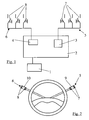
- Figure 1 shows schematically a with a control unit 1 of a motor vehicle associated control device 2.
- the control unit 1 of the motor vehicle is used for Power control of a drive device, not shown of the motor vehicle and is for example with a throttle valve, a system for injection of Fuel and an accelerator pedal of the motor vehicle connected.
- the control device 2 has an assembly 3 of a Limit speed system and an assembly 4 a vehicle speed control system.
- the assemblies 3, 4 are each connected to control units 5, 6.
- the operating units 5, 6 each have buttons 7, 8 to program or apply speeds of the motor vehicle in the individual modules 3, 4.
- buttons 7 the current vehicle speed as the limit speed into the module 3 or to increment the limit speeds in steps, for example Serve 5 km / h.
- the second of the buttons 7 could while setting the limit speed value decrement and the third button 7 to Activation or deactivation of the limit speed system serve.
- FIG. 2 shows a steering wheel of a motor vehicle with two steering column levers 9, 10.
- the left steering column lever 10 shows the buttons 8 of Figure 1 for the vehicle speed control system on, while the right one Steering column lever 9, the button 7 of Figure 1 for the limit speed system wearing.
- the limit speed system and the Driving speed control system can be each by pressing the corresponding button 7, 8 on the activate respective steering column levers 9, 10 and program.
Abstract
Description
- Fig. 1
- eine schematische Darstellung einer erfindungsgemäßen Einrichtung für ein Grenzgeschwindigkeits-System und eines Fahrgeschwindigkeits-RegelungsSystem,
- Fig. 2
- eine Ansicht auf ein Lenkrad eines Kraftfahrzeuges mit zwei Lenkstockhebeln.
- 1
- Steuergerät
- 2
- Steuereinrichtung
- 3, 4
- Baugruppe
- 5, 6
- Bedieneinheit
- 7, 8
- Taster
- 9, 10
- Lenkstockhebel
Claims (5)
- Verfahren zur Einstellung eines Grenzgeschwindigkeits-Systems und eines Fahrgeschwindigkeits-Regelungs-Systems eines Kraftfahrzeuges, bei dem eine maximal oder minimal fahrbare Grenzgeschwindigkeit festgelegt und bei dem eine konstant zu fahrende Fahrgeschwindigkeit eingestellt wird, dadurch gekennzeichnet, dass bei Bedienung des einen Systems das andere System abgeschaltet wird.
- Verfahren nach Anspruch 1, wobei zur Bedienung der beiden Systeme je eine Bedieneinheit zur Verfügung gestellt ist, dadurch gekennzeichnet, dass die Bedieneinheit (5) für das Grenzgeschwindigkeits-System von der Bedieneinheit (6) für das Fahrgeschwindigkeits-Regelungs-System räumlich getrennt ist.
- Verfahren nach Anspruch 2, dadurch gekennzeichnet, dass bei einem für die Einstellung des Fahrgeschwindigkeits-Regelungs-Systems vorgesehenen Lenkstockhebel (10) die Bedieneinheit (5) zur Einstellung des Grenzgeschwindigkeits-Systems einen weiteren Lenkstockhebel (9) aufweist.
- Verfahren nach Anspruch 3, dadurch gekennzeichnet, dass die Lenkstockhebel (9, 10) der beiden Bedieneinheiten (5, 6) einander entsprechende Schaltelemente und/oder Regelelemente haben.
- Verfahren nach Anspruch 3 oder 4, dadurch gekennzeichnet, dass die Lenkstockhebel (9, 10) spiegelbildlich zueinander angeordnet sind.
Applications Claiming Priority (3)
| Application Number | Priority Date | Filing Date | Title |
|---|---|---|---|
| DE10154385 | 2001-11-06 | ||
| DE10154385A DE10154385A1 (de) | 2001-11-06 | 2001-11-06 | Einrichtung und Verfahren zur Geschwindigkeitssteuerung bei einem Kraftfahrzeug |
| EP02024005A EP1308340B1 (de) | 2001-11-06 | 2002-10-26 | Einrichtung und Verfahren zur Geschwindigkeitssteuerung bei einem Kraftfahrzeug |
Related Parent Applications (1)
| Application Number | Title | Priority Date | Filing Date |
|---|---|---|---|
| EP02024005A Division EP1308340B1 (de) | 2001-11-06 | 2002-10-26 | Einrichtung und Verfahren zur Geschwindigkeitssteuerung bei einem Kraftfahrzeug |
Publications (1)
| Publication Number | Publication Date |
|---|---|
| EP1533172A1 true EP1533172A1 (de) | 2005-05-25 |
Family
ID=7704729
Family Applications (2)
| Application Number | Title | Priority Date | Filing Date |
|---|---|---|---|
| EP05003207A Ceased EP1533172A1 (de) | 2001-11-06 | 2002-10-26 | Verfahren zur Einstellung eines Grenzgeschwindigkeits-Systems und eines Fahrgeschwindigkeits-Regelungs-Systems eines Kraftfahrzeuges |
| EP02024005A Expired - Fee Related EP1308340B1 (de) | 2001-11-06 | 2002-10-26 | Einrichtung und Verfahren zur Geschwindigkeitssteuerung bei einem Kraftfahrzeug |
Family Applications After (1)
| Application Number | Title | Priority Date | Filing Date |
|---|---|---|---|
| EP02024005A Expired - Fee Related EP1308340B1 (de) | 2001-11-06 | 2002-10-26 | Einrichtung und Verfahren zur Geschwindigkeitssteuerung bei einem Kraftfahrzeug |
Country Status (3)
| Country | Link |
|---|---|
| EP (2) | EP1533172A1 (de) |
| DE (2) | DE10154385A1 (de) |
| ES (1) | ES2267923T3 (de) |
Citations (8)
| Publication number | Priority date | Publication date | Assignee | Title |
|---|---|---|---|---|
| US4858135A (en) * | 1984-02-24 | 1989-08-15 | Veeder-Root Limited | Tachograph and vehicle speed control device |
| DE19509494A1 (de) * | 1995-03-16 | 1996-09-19 | Daimler Benz Ag | Vorrichtung zur Regulierung der Geschwindigkeit eines Kraftfahrzeuges |
| US5665026A (en) * | 1995-03-16 | 1997-09-09 | Mercedes-Benz Ag | Method and apparatus for limiting the speed of a motor vehicle |
| US5774820A (en) * | 1994-09-23 | 1998-06-30 | Mercedes-Benz Ag | Method and apparatus for limiting the speed of a motor vehicle |
| DE19654218A1 (de) * | 1996-12-26 | 1998-07-02 | Elson Produktions Und Handels | Zusatzeinrichtung für einen Kraftfahrzeug-Geschwindigkeitsbegrenzer |
| US5794735A (en) * | 1993-11-10 | 1998-08-18 | Robert Bosch Gmbh | Vehicle deceleration by engine control followed by brake control |
| JPH11189068A (ja) * | 1997-12-25 | 1999-07-13 | Hino Motors Ltd | 速度制御装置 |
| DE19947313A1 (de) * | 1999-10-01 | 2001-04-05 | Volkswagen Ag | Vorrichtung zur Begrenzung der Geschwindigkeit eines Fahrzeuges, insbesondere eines Landfahrzeuges |
Family Cites Families (2)
| Publication number | Priority date | Publication date | Assignee | Title |
|---|---|---|---|---|
| US5739491A (en) * | 1996-03-25 | 1998-04-14 | Crosson, Jr.; Oliver J. | Lane changer apparatus |
| DE19820830C1 (de) * | 1998-05-09 | 1999-09-23 | Daimler Chrysler Ag | Fahrzeugmotorsteuerungsvorrichtung mit Regelung und/oder Begrenzung der Fahrgeschwindigkeit |
-
2001
- 2001-11-06 DE DE10154385A patent/DE10154385A1/de not_active Withdrawn
-
2002
- 2002-10-26 ES ES02024005T patent/ES2267923T3/es not_active Expired - Lifetime
- 2002-10-26 EP EP05003207A patent/EP1533172A1/de not_active Ceased
- 2002-10-26 EP EP02024005A patent/EP1308340B1/de not_active Expired - Fee Related
- 2002-10-26 DE DE50207429T patent/DE50207429D1/de not_active Expired - Lifetime
Patent Citations (8)
| Publication number | Priority date | Publication date | Assignee | Title |
|---|---|---|---|---|
| US4858135A (en) * | 1984-02-24 | 1989-08-15 | Veeder-Root Limited | Tachograph and vehicle speed control device |
| US5794735A (en) * | 1993-11-10 | 1998-08-18 | Robert Bosch Gmbh | Vehicle deceleration by engine control followed by brake control |
| US5774820A (en) * | 1994-09-23 | 1998-06-30 | Mercedes-Benz Ag | Method and apparatus for limiting the speed of a motor vehicle |
| DE19509494A1 (de) * | 1995-03-16 | 1996-09-19 | Daimler Benz Ag | Vorrichtung zur Regulierung der Geschwindigkeit eines Kraftfahrzeuges |
| US5665026A (en) * | 1995-03-16 | 1997-09-09 | Mercedes-Benz Ag | Method and apparatus for limiting the speed of a motor vehicle |
| DE19654218A1 (de) * | 1996-12-26 | 1998-07-02 | Elson Produktions Und Handels | Zusatzeinrichtung für einen Kraftfahrzeug-Geschwindigkeitsbegrenzer |
| JPH11189068A (ja) * | 1997-12-25 | 1999-07-13 | Hino Motors Ltd | 速度制御装置 |
| DE19947313A1 (de) * | 1999-10-01 | 2001-04-05 | Volkswagen Ag | Vorrichtung zur Begrenzung der Geschwindigkeit eines Fahrzeuges, insbesondere eines Landfahrzeuges |
Non-Patent Citations (1)
| Title |
|---|
| PATENT ABSTRACTS OF JAPAN vol. 1999, no. 12 29 October 1999 (1999-10-29) * |
Also Published As
| Publication number | Publication date |
|---|---|
| EP1308340B1 (de) | 2006-07-05 |
| ES2267923T3 (es) | 2007-03-16 |
| EP1308340A3 (de) | 2004-01-14 |
| DE50207429D1 (de) | 2006-08-17 |
| EP1308340A2 (de) | 2003-05-07 |
| DE10154385A1 (de) | 2003-05-15 |
Similar Documents
| Publication | Publication Date | Title |
|---|---|---|
| EP3013615B1 (de) | Vorrichtung und verfahren zum wahlweisen betreiben eines kraftfahrzeugs in einem benutzergesteuerten oder einem automatischen fahrbetriebsmodus | |
| DE102013209064B4 (de) | Fahrassistenzvorrichtungen für ein Kraftfahrzeug | |
| DE102006048947A1 (de) | Steuereinheit und Verfahren zum Verstellen eines an ein Fahrzeug angekuppelten Anhängers | |
| DE102006060554A1 (de) | Lenkrad für ein Kraftfahrzeug und Kraftfahrzeug | |
| DE10154429A1 (de) | Kraftübertragungssteuerung für Fahrzeuge | |
| WO2003022617A1 (de) | Geschwindigkeitsregelung eines kraftfahrzeuges mit automatisiertem schaltgetriebe | |
| DE102015225932A1 (de) | Bedieneinrichtung zur Vorgabe des Grads der Unterstützung durch eine Fahrerassistenz | |
| DE10052881A1 (de) | Steuervorrichtung für ein Getriebe eines Kraftfahrzeuges | |
| EP1146257B1 (de) | Vorrichtung zur Auswahl einer Fahrstufe oder Gangstufe eines Kraftfahrzeuggetriebes | |
| EP1253062A2 (de) | Überlagerungslenksystem für Kraftfahrzeuge | |
| EP0306640A2 (de) | Elektrisch ansteuerbare Stellvorrichtung zum Verstellen der Drosselklappe einer Brenngemischdrosseleinrichtung von Brennkraftmaschinen | |
| EP1129885A2 (de) | Multifunktions-Bedienelement für Fahrgeschwindigkeitsregelsystem | |
| DE102009037856A1 (de) | Verfahren und Fahrzeug mit Schaltelement zur Einstellung eines Fahrprofils des Fahrzeugs | |
| DE102004009308A1 (de) | Fahrerassistenzsystem | |
| DE19957151B4 (de) | Schaltvorrichtung | |
| EP1758758B1 (de) | Verfahren zur regelung einer elektrischen verstelleinrichtung | |
| EP1533172A1 (de) | Verfahren zur Einstellung eines Grenzgeschwindigkeits-Systems und eines Fahrgeschwindigkeits-Regelungs-Systems eines Kraftfahrzeuges | |
| WO2019052752A1 (de) | Verfahren und bewegungsvorrichtung zum bewegen zumindest eines teils einer manuell bedienbaren bedieneinrichtung zum bedienen einer funktion eines fahrzeugs und bewegungssystem mit einer bewegungsvorrichtung und einer bedieneinrichtung | |
| DE60213369T2 (de) | Steuerungsvorrichtung für ein Kraftfahrzeug | |
| EP0639706B1 (de) | System zur Ansteuerung eines Stellglieds zur Einstellung der Luftzufuhr eines Kraftfahrzeugmotors | |
| DE102010053481B4 (de) | Bedieneinrichtung für Verfahren eines Fahrzeugs | |
| DE102019207615A1 (de) | Verfahren zur Regelung einer Bewegung einer Lenkhandhabe eines Lenksystems | |
| DE19964419B4 (de) | Schaltvorrichtung | |
| DE19802706B4 (de) | Elektronisch gesteuerter Fahrgeschwindigkeitsregler | |
| DE102004032536B4 (de) | Vorrichtung und Verfahren zum Betreiben einer Antriebseinheit |
Legal Events
| Date | Code | Title | Description |
|---|---|---|---|
| PUAI | Public reference made under article 153(3) epc to a published international application that has entered the european phase |
Free format text: ORIGINAL CODE: 0009012 |
|
| AC | Divisional application: reference to earlier application |
Ref document number: 1308340 Country of ref document: EP Kind code of ref document: P |
|
| AK | Designated contracting states |
Kind code of ref document: A1 Designated state(s): AT BE BG CH CY CZ DE DK EE ES FI FR GB GR IE IT LI LU MC NL PT SE SK TR |
|
| 17P | Request for examination filed |
Effective date: 20050628 |
|
| AKX | Designation fees paid |
Designated state(s): DE ES FR GB IT |
|
| STAA | Information on the status of an ep patent application or granted ep patent |
Free format text: STATUS: THE APPLICATION HAS BEEN REFUSED |
|
| 18R | Application refused |
Effective date: 20060512 |