EP1533104A2 - Verfahren zur Herstellung eines Laufrades für eine Kreiselpumpe - Google Patents
Verfahren zur Herstellung eines Laufrades für eine Kreiselpumpe Download PDFInfo
- Publication number
- EP1533104A2 EP1533104A2 EP04105334A EP04105334A EP1533104A2 EP 1533104 A2 EP1533104 A2 EP 1533104A2 EP 04105334 A EP04105334 A EP 04105334A EP 04105334 A EP04105334 A EP 04105334A EP 1533104 A2 EP1533104 A2 EP 1533104A2
- Authority
- EP
- European Patent Office
- Prior art keywords
- cover plate
- blades
- impeller
- rear cover
- grooves
- Prior art date
- Legal status (The legal status is an assumption and is not a legal conclusion. Google has not performed a legal analysis and makes no representation as to the accuracy of the status listed.)
- Granted
Links
Images

Classifications
-
- B—PERFORMING OPERATIONS; TRANSPORTING
- B29—WORKING OF PLASTICS; WORKING OF SUBSTANCES IN A PLASTIC STATE IN GENERAL
- B29C—SHAPING OR JOINING OF PLASTICS; SHAPING OF MATERIAL IN A PLASTIC STATE, NOT OTHERWISE PROVIDED FOR; AFTER-TREATMENT OF THE SHAPED PRODUCTS, e.g. REPAIRING
- B29C65/00—Joining or sealing of preformed parts, e.g. welding of plastics materials; Apparatus therefor
-
- B—PERFORMING OPERATIONS; TRANSPORTING
- B29—WORKING OF PLASTICS; WORKING OF SUBSTANCES IN A PLASTIC STATE IN GENERAL
- B29C—SHAPING OR JOINING OF PLASTICS; SHAPING OF MATERIAL IN A PLASTIC STATE, NOT OTHERWISE PROVIDED FOR; AFTER-TREATMENT OF THE SHAPED PRODUCTS, e.g. REPAIRING
- B29C66/00—General aspects of processes or apparatus for joining preformed parts
- B29C66/01—General aspects dealing with the joint area or with the area to be joined
- B29C66/05—Particular design of joint configurations
- B29C66/10—Particular design of joint configurations particular design of the joint cross-sections
- B29C66/12—Joint cross-sections combining only two joint-segments; Tongue and groove joints; Tenon and mortise joints; Stepped joint cross-sections
- B29C66/124—Tongue and groove joints
- B29C66/1244—Tongue and groove joints characterised by the male part, i.e. the part comprising the tongue
- B29C66/12441—Tongue and groove joints characterised by the male part, i.e. the part comprising the tongue being a single wall
-
- B—PERFORMING OPERATIONS; TRANSPORTING
- B29—WORKING OF PLASTICS; WORKING OF SUBSTANCES IN A PLASTIC STATE IN GENERAL
- B29C—SHAPING OR JOINING OF PLASTICS; SHAPING OF MATERIAL IN A PLASTIC STATE, NOT OTHERWISE PROVIDED FOR; AFTER-TREATMENT OF THE SHAPED PRODUCTS, e.g. REPAIRING
- B29C66/00—General aspects of processes or apparatus for joining preformed parts
- B29C66/01—General aspects dealing with the joint area or with the area to be joined
- B29C66/05—Particular design of joint configurations
- B29C66/301—Three-dimensional joints, i.e. the joined area being substantially non-flat
-
- B—PERFORMING OPERATIONS; TRANSPORTING
- B29—WORKING OF PLASTICS; WORKING OF SUBSTANCES IN A PLASTIC STATE IN GENERAL
- B29C—SHAPING OR JOINING OF PLASTICS; SHAPING OF MATERIAL IN A PLASTIC STATE, NOT OTHERWISE PROVIDED FOR; AFTER-TREATMENT OF THE SHAPED PRODUCTS, e.g. REPAIRING
- B29C66/00—General aspects of processes or apparatus for joining preformed parts
- B29C66/50—General aspects of joining tubular articles; General aspects of joining long products, i.e. bars or profiled elements; General aspects of joining single elements to tubular articles, hollow articles or bars; General aspects of joining several hollow-preforms to form hollow or tubular articles
- B29C66/51—Joining tubular articles, profiled elements or bars; Joining single elements to tubular articles, hollow articles or bars; Joining several hollow-preforms to form hollow or tubular articles
- B29C66/53—Joining single elements to tubular articles, hollow articles or bars
- B29C66/534—Joining single elements to open ends of tubular or hollow articles or to the ends of bars
- B29C66/5344—Joining single elements to open ends of tubular or hollow articles or to the ends of bars said single elements being substantially annular, i.e. of finite length, e.g. joining flanges to tube ends
-
- B—PERFORMING OPERATIONS; TRANSPORTING
- B29—WORKING OF PLASTICS; WORKING OF SUBSTANCES IN A PLASTIC STATE IN GENERAL
- B29C—SHAPING OR JOINING OF PLASTICS; SHAPING OF MATERIAL IN A PLASTIC STATE, NOT OTHERWISE PROVIDED FOR; AFTER-TREATMENT OF THE SHAPED PRODUCTS, e.g. REPAIRING
- B29C66/00—General aspects of processes or apparatus for joining preformed parts
- B29C66/50—General aspects of joining tubular articles; General aspects of joining long products, i.e. bars or profiled elements; General aspects of joining single elements to tubular articles, hollow articles or bars; General aspects of joining several hollow-preforms to form hollow or tubular articles
- B29C66/51—Joining tubular articles, profiled elements or bars; Joining single elements to tubular articles, hollow articles or bars; Joining several hollow-preforms to form hollow or tubular articles
- B29C66/54—Joining several hollow-preforms, e.g. half-shells, to form hollow articles, e.g. for making balls, containers; Joining several hollow-preforms, e.g. half-cylinders, to form tubular articles
-
- F—MECHANICAL ENGINEERING; LIGHTING; HEATING; WEAPONS; BLASTING
- F04—POSITIVE - DISPLACEMENT MACHINES FOR LIQUIDS; PUMPS FOR LIQUIDS OR ELASTIC FLUIDS
- F04D—NON-POSITIVE-DISPLACEMENT PUMPS
- F04D29/00—Details, component parts, or accessories
- F04D29/18—Rotors
- F04D29/22—Rotors specially for centrifugal pumps
- F04D29/2205—Conventional flow pattern
- F04D29/2222—Construction and assembly
- F04D29/2227—Construction and assembly for special materials
-
- B—PERFORMING OPERATIONS; TRANSPORTING
- B29—WORKING OF PLASTICS; WORKING OF SUBSTANCES IN A PLASTIC STATE IN GENERAL
- B29C—SHAPING OR JOINING OF PLASTICS; SHAPING OF MATERIAL IN A PLASTIC STATE, NOT OTHERWISE PROVIDED FOR; AFTER-TREATMENT OF THE SHAPED PRODUCTS, e.g. REPAIRING
- B29C65/00—Joining or sealing of preformed parts, e.g. welding of plastics materials; Apparatus therefor
- B29C65/02—Joining or sealing of preformed parts, e.g. welding of plastics materials; Apparatus therefor by heating, with or without pressure
- B29C65/08—Joining or sealing of preformed parts, e.g. welding of plastics materials; Apparatus therefor by heating, with or without pressure using ultrasonic vibrations
-
- B—PERFORMING OPERATIONS; TRANSPORTING
- B29—WORKING OF PLASTICS; WORKING OF SUBSTANCES IN A PLASTIC STATE IN GENERAL
- B29C—SHAPING OR JOINING OF PLASTICS; SHAPING OF MATERIAL IN A PLASTIC STATE, NOT OTHERWISE PROVIDED FOR; AFTER-TREATMENT OF THE SHAPED PRODUCTS, e.g. REPAIRING
- B29C65/00—Joining or sealing of preformed parts, e.g. welding of plastics materials; Apparatus therefor
- B29C65/02—Joining or sealing of preformed parts, e.g. welding of plastics materials; Apparatus therefor by heating, with or without pressure
- B29C65/14—Joining or sealing of preformed parts, e.g. welding of plastics materials; Apparatus therefor by heating, with or without pressure using wave energy, i.e. electromagnetic radiation, or particle radiation
- B29C65/16—Laser beams
-
- B—PERFORMING OPERATIONS; TRANSPORTING
- B29—WORKING OF PLASTICS; WORKING OF SUBSTANCES IN A PLASTIC STATE IN GENERAL
- B29C—SHAPING OR JOINING OF PLASTICS; SHAPING OF MATERIAL IN A PLASTIC STATE, NOT OTHERWISE PROVIDED FOR; AFTER-TREATMENT OF THE SHAPED PRODUCTS, e.g. REPAIRING
- B29C65/00—Joining or sealing of preformed parts, e.g. welding of plastics materials; Apparatus therefor
- B29C65/48—Joining or sealing of preformed parts, e.g. welding of plastics materials; Apparatus therefor using adhesives, i.e. using supplementary joining material; solvent bonding
-
- B—PERFORMING OPERATIONS; TRANSPORTING
- B29—WORKING OF PLASTICS; WORKING OF SUBSTANCES IN A PLASTIC STATE IN GENERAL
- B29L—INDEXING SCHEME ASSOCIATED WITH SUBCLASS B29C, RELATING TO PARTICULAR ARTICLES
- B29L2031/00—Other particular articles
- B29L2031/748—Machines or parts thereof not otherwise provided for
- B29L2031/7496—Pumps
-
- F—MECHANICAL ENGINEERING; LIGHTING; HEATING; WEAPONS; BLASTING
- F05—INDEXING SCHEMES RELATING TO ENGINES OR PUMPS IN VARIOUS SUBCLASSES OF CLASSES F01-F04
- F05D—INDEXING SCHEME FOR ASPECTS RELATING TO NON-POSITIVE-DISPLACEMENT MACHINES OR ENGINES, GAS-TURBINES OR JET-PROPULSION PLANTS
- F05D2230/00—Manufacture
- F05D2230/20—Manufacture essentially without removing material
- F05D2230/23—Manufacture essentially without removing material by permanently joining parts together
- F05D2230/232—Manufacture essentially without removing material by permanently joining parts together by welding
- F05D2230/234—Laser welding
-
- F—MECHANICAL ENGINEERING; LIGHTING; HEATING; WEAPONS; BLASTING
- F05—INDEXING SCHEMES RELATING TO ENGINES OR PUMPS IN VARIOUS SUBCLASSES OF CLASSES F01-F04
- F05D—INDEXING SCHEME FOR ASPECTS RELATING TO NON-POSITIVE-DISPLACEMENT MACHINES OR ENGINES, GAS-TURBINES OR JET-PROPULSION PLANTS
- F05D2300/00—Materials; Properties thereof
- F05D2300/40—Organic materials
- F05D2300/43—Synthetic polymers, e.g. plastics; Rubber
Definitions
- Impellers for centrifugal pumps are known. In “Basics for the planning of centrifugal pump systems ", Fritz Brüchler, Dennis Carter, Peter Fandrey, Jan Fischer, Ralf Mann, 7. revised and expanded edition 2000, p. 44, sterling SIHI GmbH "is referred to various impeller shapes. So one distinguishes for example radial wheels and Halbaxialmann. Frequently impellers exist for centrifugal pumps from a rear cover disc and a front Cover disc between which blades for the promotional Medium are arranged. For some purposes exist such plastic wheels.
- Impellers In the production of such Impellers, it is generally desirable in one single working step by an injection molding process produce, which in structurally complex impeller shapes However, it is not possible, because after the production of a such impeller extension of the injection molds technically can not be done.
- the invention is the task underlying, a method for producing an impeller for to create a centrifugal pump, in a relatively simple way can be realized, with the proportion of additional Lanyards should be as low as possible.
- the object underlying the invention is achieved by a Process for producing an impeller for a Centrifugal pump solved, in which a first part, from the rear cover plate with connection piece for the drive consists, at the, facing away from the connecting piece Side blades are arranged, as an individual part Plastic is produced in an injection molding process and then a second piece of plastic, which is the front Cover disc represents and on its inside with grooves is provided, which is complementary to the, the rear Cover disc facing away edges of the blades formed are put on the first part, with each of the Rear cover plate facing away edge of the blades in one complementarily formed groove engages and thereby a Connection of the first part with the second part takes place.
- the term impeller are radial and semi-axial To understand wheels.
- connection piece for the drive can be made for example in the form of a pipe socket be.
- Suitable plastics are those by injection molding machinable plastics, whereby the selection according to the Intended purpose of the impeller of the centrifugal pump.
- the front cover plate is usually part-circular trained and runs as a result of flow technology arched or conical. Under the complementary education The grooves are to be understood as a course of grooves, that of the one who Rear cover plate facing away from the blades so corresponds so that these edges are introduced into the grooves can be.
- a preferred embodiment of the invention is then the compound by ultrasonic or Laser welding is enhanced. That way you can do that Impeller in an even larger number of applications deploy.
- the rear cover disc opposite edges of the blades or the grooves in front of the Place the second part on the first part with adhesive be painted. It is possible, either the edges the blades or the grooves or both the edges as well brush the grooves with glue. The must groove or the edges may not be completely wetted with adhesive. It is usually sufficient to use the glue very sparingly Apply punctiform. This way becomes a special one fixed connection of the first part with the second part achieved, at the same time the amount of additional Lanyard in the form of adhesive is minimized and the impeller is relatively accessible for many uses.
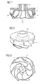
- the impeller is shown in longitudinal section.
- the flowing medium which is usually a Liquid acts, the impeller thereby in the arrow direction fed.
- the impeller has a first part which extends from the Rear cover plate 1 with connector 1a for the drive (not shown). At the rear cover disc 1 are on their side facing away from the connection piece 1a Blades 1 * arranged.
- the first part is made of plastic produced in an injection molding process.
- the impeller points Furthermore, a second part made of plastic, which is the front Cover plate 2 represents and is provided with grooves 2a, the opposite to the rear cover plate 1 facing away Edges of the blades 1 * are formed.
- each of the rear cover plate. 1 facing away edge of the blades 1 * in a complementary trained groove 2a engages and thereby connect the first part with the second part.
- the first part of the impeller is three-dimensional shown. It represents the rear cover plate 1 with the Connecting piece 1a for the drive (not shown), on the, on its side facing away from the connection piece 1a Blades 1 * are arranged.
- the first part is as Item made of plastic in an injection molding process been prepared.
- the first part of the impeller is three-dimensional with a view of the blades 1 * shown.
- the Connector 1a has the form of a pipe socket, wherein this form for the connector 1a, however, not mandatory is.
- Fig. 4 is the outside of the second part of the impeller shown in three dimensions.
- the second part represents the front cover plate 2 is and is part-circular, conical running trained.
- On its inside 2 * is the second part provided with grooves 2a, which are complementary to the the rear cover plate 1 to turn edges of the blades (not shown) are formed.
- a connection of the first part with the second part can in an advantageous way for many purposes without the Arrangement of additional connecting means done.
Landscapes
- Engineering & Computer Science (AREA)
- Mechanical Engineering (AREA)
- General Engineering & Computer Science (AREA)
- Structures Of Non-Positive Displacement Pumps (AREA)
Abstract
Description
- Fig. 1
- zeigt das Laufrad im Längsschnitt;
- Fig. 2
- zeigt das erste Teil des Laufrades in dreidimensionaler Form;
- Fig. 3
- zeigt die Unterseite des ersten Teiles des Laufrades mit Blick auf die Schaufeln in dreidimensionaler Form;
- Fig. 4
- zeigt die Außenseite des zweiten Teiles des Laufrades in dreidimensionaler Form;
- Fig. 5
- zeigt die Innenseite des zweiten Teiles des Laufrades in dreidimensionaler Form.
Claims (3)
- Verfahren zur Herstellung eines Laufrades für eine Kreiselpumpe, bei dem ein erstes Teil, das aus der hinteren Deckscheibe (1) mit Anschlussstück (1a) für den Antrieb besteht, an der, an ihrer dem Anschlussstück (1a) abgewandten Seite Schaufeln (1*) angeordnet sind, als Einzelteil aus Kunststoff in einem Spritzgießverfahren hergestellt wird und anschließend ein zweites Teil aus Kunststoff, das die vordere Deckscheibe (2) darstellt und an seiner Innenseite (2*) mit Nuten (2a) versehen ist, die komplementär zu den, der hinteren Deckscheibe (1) abgewandten Kanten der Schaufeln (1*) ausgebildet sind, auf das erste Teil aufgesetzt wird, wobei jede der hinteren Deckscheibe (1) abgewandte Kante der Schaufeln (1*) in eine komplementär ausgebildete Nut (2a) eingreift und dadurch eine Verbindung des ersten Teiles mit dem zweiten Teil erfolgt.
- Verfahren nach Anspruch 1, bei dem die Verbindung anschließend durch Ultraschall- oder Laserschweißen verstärkt wird.
- Verfahren nach Anspruch 1, bei dem die der hinteren Deckscheibe (1) abgewandten Kanten der Schaufeln (1*) oder die Nuten (2a) vor dem Aufsetzen des zweiten Teiles auf das erste Teil mit Klebstoff bestrichen werden.
Applications Claiming Priority (2)
| Application Number | Priority Date | Filing Date | Title |
|---|---|---|---|
| DE10354749A DE10354749A1 (de) | 2003-11-21 | 2003-11-21 | Verfahren zur Herstellung eines Laufrades für eine Kreiselpumpe |
| DE10354749 | 2003-11-21 |
Publications (3)
| Publication Number | Publication Date |
|---|---|
| EP1533104A2 true EP1533104A2 (de) | 2005-05-25 |
| EP1533104A3 EP1533104A3 (de) | 2006-12-20 |
| EP1533104B1 EP1533104B1 (de) | 2011-04-27 |
Family
ID=34428870
Family Applications (1)
| Application Number | Title | Priority Date | Filing Date |
|---|---|---|---|
| EP04105334A Expired - Lifetime EP1533104B1 (de) | 2003-11-21 | 2004-10-27 | Verfahren zur Herstellung eines Laufrades für eine Kreiselpumpe |
Country Status (2)
| Country | Link |
|---|---|
| EP (1) | EP1533104B1 (de) |
| DE (2) | DE10354749A1 (de) |
Cited By (6)
| Publication number | Priority date | Publication date | Assignee | Title |
|---|---|---|---|---|
| WO2007003265A1 (de) * | 2005-07-06 | 2007-01-11 | Schaeffler Kg | Wasserpumpenflügelrad |
| WO2009092711A1 (de) | 2008-01-25 | 2009-07-30 | Bitter Engineering & Systemtechnik Gmbh | Laufrad für eine pumpe |
| CN101793264A (zh) * | 2010-04-28 | 2010-08-04 | 自贡市红旗泵业密封件制造有限公司 | 脱硫循环泵叶轮的制造方法 |
| CN103143900A (zh) * | 2013-04-02 | 2013-06-12 | 哈尔滨电机厂有限责任公司 | 立轴单级单吸离心式大型水泵泵轮的焊接制造工艺方法 |
| CN109253108A (zh) * | 2018-11-14 | 2019-01-22 | 刘子鸣 | 一种注塑成型的潜水泵闭式叶轮及其生产方法 |
| DE102020118982A1 (de) | 2020-07-17 | 2022-01-20 | Nidec Gpm Gmbh | Laufrad für eine Zentrifugalflüssigkeitspumpe sowie Zentrifugalflüssigkeitspumpe aufweisend das Laufrad und Kraftfahrzeug aufweisend eine solche Zentrifugalfluidpumpe |
Families Citing this family (1)
| Publication number | Priority date | Publication date | Assignee | Title |
|---|---|---|---|---|
| WO2012051642A1 (en) * | 2010-09-24 | 2012-04-26 | New Fluid Technology Pty Ltd | Impeller assembly method |
Citations (1)
| Publication number | Priority date | Publication date | Assignee | Title |
|---|---|---|---|---|
| JPS59103998A (ja) | 1982-12-06 | 1984-06-15 | Hitachi Ltd | ポンプ用羽根車 |
Family Cites Families (12)
| Publication number | Priority date | Publication date | Assignee | Title |
|---|---|---|---|---|
| JPS5664198A (en) * | 1979-10-27 | 1981-06-01 | Mikuni Plast Kk | Impeller combining method |
| JPS6146493A (ja) * | 1985-07-24 | 1986-03-06 | Hitachi Ltd | ポンプ用羽根車 |
| DE3611910A1 (de) * | 1986-04-09 | 1987-10-15 | Schaeffler Waelzlager Kg | Laufrad fuer eine radialpumpe |
| JPH078535B2 (ja) * | 1987-12-18 | 1995-02-01 | 松下電器産業株式会社 | 超音波溶着方法 |
| JP2757511B2 (ja) * | 1989-12-25 | 1998-05-25 | 松下電器産業株式会社 | 送風機用インペラの製造方法 |
| JPH0545310A (ja) * | 1991-08-13 | 1993-02-23 | Jeol Ltd | X線モノクロメータ |
| FR2703111B1 (fr) * | 1993-03-25 | 1995-06-30 | Ozen Sa | Rotor pour pompe comportant deux pieces assemblees par soudure, obtenues par moulage par injection de materiaux thermoplastiques, et procede de fabrication d'un tel rotor . |
| KR100198393B1 (ko) * | 1996-11-21 | 1999-06-15 | 전주범 | 펌프 임펠러 제조방법 및 장치 |
| DE19701297A1 (de) * | 1997-01-16 | 1998-07-23 | Wilo Gmbh | Laufrad einer Kreiselpumpe |
| DE29713027U1 (de) * | 1997-07-23 | 1998-11-19 | Pahling, Walter, Dipl.-Ing., 27755 Delmenhorst | Extrem-Leichtbauweise für große Ventilator-Laufräder |
| DE19742023B4 (de) * | 1997-09-24 | 2006-07-13 | Beez, Günther, Dipl.-Ing. | Laufrad |
| DE19906645A1 (de) * | 1999-02-18 | 2000-08-24 | Abb Research Ltd | Zentrifugalimpeller |
-
2003
- 2003-11-21 DE DE10354749A patent/DE10354749A1/de not_active Withdrawn
-
2004
- 2004-10-27 DE DE502004012437T patent/DE502004012437D1/de not_active Expired - Lifetime
- 2004-10-27 EP EP04105334A patent/EP1533104B1/de not_active Expired - Lifetime
Patent Citations (1)
| Publication number | Priority date | Publication date | Assignee | Title |
|---|---|---|---|---|
| JPS59103998A (ja) | 1982-12-06 | 1984-06-15 | Hitachi Ltd | ポンプ用羽根車 |
Non-Patent Citations (1)
| Title |
|---|
| FRITZ BRÜCHLER; DENNIS CARTER; PETER FANDREY; JAN FISCHER; RALF MANN: "Grundlagen für die Planung von Kreiselpumpenanlagen", 2000, STERLING SIHI GMBH, pages: 44 |
Cited By (9)
| Publication number | Priority date | Publication date | Assignee | Title |
|---|---|---|---|---|
| WO2007003265A1 (de) * | 2005-07-06 | 2007-01-11 | Schaeffler Kg | Wasserpumpenflügelrad |
| WO2009092711A1 (de) | 2008-01-25 | 2009-07-30 | Bitter Engineering & Systemtechnik Gmbh | Laufrad für eine pumpe |
| CN101793264A (zh) * | 2010-04-28 | 2010-08-04 | 自贡市红旗泵业密封件制造有限公司 | 脱硫循环泵叶轮的制造方法 |
| CN103143900A (zh) * | 2013-04-02 | 2013-06-12 | 哈尔滨电机厂有限责任公司 | 立轴单级单吸离心式大型水泵泵轮的焊接制造工艺方法 |
| CN103143900B (zh) * | 2013-04-02 | 2015-06-24 | 哈尔滨电机厂有限责任公司 | 立轴单级单吸离心式大型水泵泵轮的焊接制造工艺 |
| CN109253108A (zh) * | 2018-11-14 | 2019-01-22 | 刘子鸣 | 一种注塑成型的潜水泵闭式叶轮及其生产方法 |
| DE102020118982A1 (de) | 2020-07-17 | 2022-01-20 | Nidec Gpm Gmbh | Laufrad für eine Zentrifugalflüssigkeitspumpe sowie Zentrifugalflüssigkeitspumpe aufweisend das Laufrad und Kraftfahrzeug aufweisend eine solche Zentrifugalfluidpumpe |
| WO2022013107A1 (de) | 2020-07-17 | 2022-01-20 | Nidec Gpm Gmbh | Laufrad für eine zentrifugalflüssigkeitspumpe sowie zentrifugalflüssigkeitspumpe aufweisend das laufrad und kraftfahrzeug aufweisend eine solche zentrifugalfluidpumpe |
| DE102020118982B4 (de) | 2020-07-17 | 2024-06-06 | Nidec Gpm Gmbh | Laufrad für eine Zentrifugalflüssigkeitspumpe sowie Zentrifugalflüssigkeitspumpe aufweisend das Laufrad und Kraftfahrzeug aufweisend eine solche Zentrifugalfluidpumpe |
Also Published As
| Publication number | Publication date |
|---|---|
| EP1533104A3 (de) | 2006-12-20 |
| DE10354749A1 (de) | 2005-06-23 |
| DE502004012437D1 (de) | 2011-06-09 |
| EP1533104B1 (de) | 2011-04-27 |
Similar Documents
| Publication | Publication Date | Title |
|---|---|---|
| DE68908086T3 (de) | Fahrzeugrad. | |
| DE20013706U1 (de) | Lenkrad mit Dekorelement | |
| EP1533104A2 (de) | Verfahren zur Herstellung eines Laufrades für eine Kreiselpumpe | |
| DE4139293C2 (de) | ||
| LU82849A1 (de) | Konstruktionseinheit fuer stroemungstechnische einrichtungen oder maschinen | |
| DE60308371T2 (de) | Verbesserte endbearbeitung für fussbodenbelag | |
| DE19523870A1 (de) | Ansaugeinrichtung aus thermoplastischem Kunststoff | |
| DE2942086A1 (de) | Wischarm, insbesondere fuer wischanlagen an kraftfahrzeugen | |
| DE3310062C2 (de) | ||
| DE3342718A1 (de) | Funktionales formgestaltungselement fuer dreidimensionale koerper | |
| DE202018101119U1 (de) | Kugelgelenk | |
| DE69510805T2 (de) | Verfahren zum herstellen einer platte beschichtet mit einer verblendungsfläche, insbesondere textil | |
| DE60005410T2 (de) | Verbindung eines Körpers an einem Tragstruktur | |
| DE10354750A1 (de) | Verfahren zur Herstellung eines Laufrades für eine Kreiselpumpe | |
| EP0797735B1 (de) | Laufradbefestigung | |
| DE19833314C2 (de) | Verfahren zum Herstellen eines Lenkrades | |
| DE102011112135A1 (de) | Verkleidungsteil | |
| DE602004012516T2 (de) | Hydraulikaggregat für eine blockiergeschützte Fahrzeugbremsanlage und Verfahren zur dessen Herstellung | |
| WO1992014597A1 (de) | Verfahren zur herstellung einer gelenkscheibe | |
| DE202004009722U1 (de) | Rückschlagventil | |
| DE102016109760A1 (de) | Befestiger zur Befestigung eines zu befestigenden Elements an ein Trägerteil eines Fahrzeugs mit verringertem Korrosionsrisiko | |
| DE102004062008A1 (de) | Kraftstofffilter mit Auslassöffnungen, die vorzugsweise mit einem hydroerosiven Verfahren bearbeitet sind | |
| DE60223318T2 (de) | Verbundplatte mit Holzoberfläche zur Herstellung von Möbeln, Wänden, Türen | |
| DE19918286A1 (de) | Inducer | |
| DE19824720C1 (de) | Verfahren zum Herstellen von langgestreckten Verbundprofilen und Verbundprofil |
Legal Events
| Date | Code | Title | Description |
|---|---|---|---|
| PUAI | Public reference made under article 153(3) epc to a published international application that has entered the european phase |
Free format text: ORIGINAL CODE: 0009012 |
|
| AK | Designated contracting states |
Kind code of ref document: A2 Designated state(s): AT BE BG CH CY CZ DE DK EE ES FI FR GB GR HU IE IT LI LU MC NL PL PT RO SE SI SK TR |
|
| AX | Request for extension of the european patent |
Extension state: AL HR LT LV MK |
|
| PUAL | Search report despatched |
Free format text: ORIGINAL CODE: 0009013 |
|
| AK | Designated contracting states |
Kind code of ref document: A3 Designated state(s): AT BE BG CH CY CZ DE DK EE ES FI FR GB GR HU IE IT LI LU MC NL PL PT RO SE SI SK TR |
|
| AX | Request for extension of the european patent |
Extension state: AL HR LT LV MK |
|
| 17P | Request for examination filed |
Effective date: 20070108 |
|
| AKX | Designation fees paid |
Designated state(s): DE ES FR GB IT |
|
| RAP1 | Party data changed (applicant data changed or rights of an application transferred) |
Owner name: CONTINENTAL AUTOMOTIVE GMBH |
|
| 17Q | First examination report despatched |
Effective date: 20091002 |
|
| GRAP | Despatch of communication of intention to grant a patent |
Free format text: ORIGINAL CODE: EPIDOSNIGR1 |
|
| GRAS | Grant fee paid |
Free format text: ORIGINAL CODE: EPIDOSNIGR3 |
|
| GRAA | (expected) grant |
Free format text: ORIGINAL CODE: 0009210 |
|
| AK | Designated contracting states |
Kind code of ref document: B1 Designated state(s): DE ES FR GB IT |
|
| REG | Reference to a national code |
Ref country code: GB Ref legal event code: FG4D Free format text: NOT ENGLISH |
|
| REF | Corresponds to: |
Ref document number: 502004012437 Country of ref document: DE Date of ref document: 20110609 Kind code of ref document: P |
|
| REG | Reference to a national code |
Ref country code: DE Ref legal event code: R096 Ref document number: 502004012437 Country of ref document: DE Effective date: 20110609 |
|
| PG25 | Lapsed in a contracting state [announced via postgrant information from national office to epo] |
Ref country code: ES Free format text: LAPSE BECAUSE OF FAILURE TO SUBMIT A TRANSLATION OF THE DESCRIPTION OR TO PAY THE FEE WITHIN THE PRESCRIBED TIME-LIMIT Effective date: 20110807 |
|
| PLBE | No opposition filed within time limit |
Free format text: ORIGINAL CODE: 0009261 |
|
| STAA | Information on the status of an ep patent application or granted ep patent |
Free format text: STATUS: NO OPPOSITION FILED WITHIN TIME LIMIT |
|
| 26N | No opposition filed |
Effective date: 20120130 |
|
| REG | Reference to a national code |
Ref country code: DE Ref legal event code: R097 Ref document number: 502004012437 Country of ref document: DE Effective date: 20120130 |
|
| GBPC | Gb: european patent ceased through non-payment of renewal fee |
Effective date: 20111027 |
|
| PG25 | Lapsed in a contracting state [announced via postgrant information from national office to epo] |
Ref country code: GB Free format text: LAPSE BECAUSE OF NON-PAYMENT OF DUE FEES Effective date: 20111027 |
|
| PGFP | Annual fee paid to national office [announced via postgrant information from national office to epo] |
Ref country code: FR Payment date: 20121031 Year of fee payment: 9 |
|
| PGFP | Annual fee paid to national office [announced via postgrant information from national office to epo] |
Ref country code: IT Payment date: 20121024 Year of fee payment: 9 |
|
| REG | Reference to a national code |
Ref country code: FR Ref legal event code: ST Effective date: 20140630 |
|
| PG25 | Lapsed in a contracting state [announced via postgrant information from national office to epo] |
Ref country code: IT Free format text: LAPSE BECAUSE OF NON-PAYMENT OF DUE FEES Effective date: 20131027 Ref country code: FR Free format text: LAPSE BECAUSE OF NON-PAYMENT OF DUE FEES Effective date: 20131031 |
|
| PGFP | Annual fee paid to national office [announced via postgrant information from national office to epo] |
Ref country code: DE Payment date: 20171031 Year of fee payment: 14 |
|
| REG | Reference to a national code |
Ref country code: DE Ref legal event code: R119 Ref document number: 502004012437 Country of ref document: DE |
|
| PG25 | Lapsed in a contracting state [announced via postgrant information from national office to epo] |
Ref country code: DE Free format text: LAPSE BECAUSE OF NON-PAYMENT OF DUE FEES Effective date: 20190501 |