EP1532859A1 - Knoteranordnung - Google Patents
Knoteranordnung Download PDFInfo
- Publication number
- EP1532859A1 EP1532859A1 EP04105844A EP04105844A EP1532859A1 EP 1532859 A1 EP1532859 A1 EP 1532859A1 EP 04105844 A EP04105844 A EP 04105844A EP 04105844 A EP04105844 A EP 04105844A EP 1532859 A1 EP1532859 A1 EP 1532859A1
- Authority
- EP
- European Patent Office
- Prior art keywords
- knotter
- spacer
- drive shaft
- adjacent
- drive
- Prior art date
- Legal status (The legal status is an assumption and is not a legal conclusion. Google has not performed a legal analysis and makes no representation as to the accuracy of the status listed.)
- Granted
Links
- 125000006850 spacer group Chemical group 0.000 claims description 42
- 238000000926 separation method Methods 0.000 abstract 1
- 230000000712 assembly Effects 0.000 description 3
- 238000000429 assembly Methods 0.000 description 3
- 230000001419 dependent effect Effects 0.000 description 1
- 238000000034 method Methods 0.000 description 1
Images
Classifications
-
- A—HUMAN NECESSITIES
- A01—AGRICULTURE; FORESTRY; ANIMAL HUSBANDRY; HUNTING; TRAPPING; FISHING
- A01F—PROCESSING OF HARVESTED PRODUCE; HAY OR STRAW PRESSES; DEVICES FOR STORING AGRICULTURAL OR HORTICULTURAL PRODUCE
- A01F15/00—Baling presses for straw, hay or the like
- A01F15/08—Details
- A01F15/14—Tying devices specially adapted for baling presses
- A01F15/145—Twine knotters
Definitions
- the invention relates to a Knoteran extract with a Drive shaft, a plurality of on this drive shaft mounted Knoter units each with a drive gear with a hub which is placed on the drive shaft in such a way is that they rotate with this and with respect to the Drive shaft can be moved in the axial direction, and a Adjustment device, which has an axial gap between opposite end surfaces adjacent to each other Knoteröen spans adjustable so that they axial extent of the gap determined.
- Conventional twine tying or Knoteran extract a Baler for producing square bales or Square bales usually have a plurality Knotter assemblies or units on side by side a drive shaft are arranged, wherein the number of Knot units the number of yarn loops corresponds to the order the bales are looped and being this number Yarn loops are dependent on the size of the bale produced is.
- Each knotter unit has a support frame, which has a Carries a plurality of knot components or assemblies / groups, and a drive gear.
- the support frame is either on the drive shaft adjacent to the drive gear or on arranged a hub of an associated drive gear, the latter being an intermediate gear, the tooth segments which are arranged to correspond with To mesh drive gears of selected knotter components, and cam surfaces to engage cam rollers or followers attack to control the movement of the knotter components.
- the support frames are fixed while the Drive shaft or hubs freely in a cuff or rotate one eye of the support frame.
- An alignment of the Drive gear and the driven components takes place using spacers, spacers or others Institutions.
- DE-A-2 736 649 shows a strapping device for a Baler with several arranged on a shaft Verschnürritten.
- an adjustment element pair with two bevelled, interlocking elements provided for adjusting the distance between the Verschnüriseren can be twisted against each other then each by means of a fastening screw on the shaft to be secured.
- the knotter arrangement has a drive shaft, a plurality of on this Drive shaft attached Knoterritten with one each Drive gear with a hub, which is on the drive shaft is set up so that they rotate with this and with With respect to the drive shaft to be moved in the axial direction can, and an adjuster on, which has an axial gap between opposite faces to each other adjusts adjacent Knoterritten adjustable, that it determines the axial extent of the gap.
- the Adjustment device has at least one adjustment, by its in or out the axial distance between the knotter units can be adjusted, and a Securing element, by means of which the adjustment detachable is determinable.
- a screwing in or out is an axial movement of one with a thread (external thread, Internally threaded) provided with respect to a first component another, with a matching or corresponding thread (Internal thread, external thread) provided component to understand.
- a first threaded hole in an axial surface or an end surface of each Drive gear provided, in which a setting means in shape a spacer screw is screwed, the head with a Front or end face of the hub of the adjacent Drive gear cooperates or rests against this.
- a Distance adjustment may be during a mounting of the Drive gears are carried on the drive shaft, by the adjusting means or the distance screws in one first direction to be screwed to the hub drive in or out in the other direction to get them out of the hub.
- the spacer screw can be a be provided self-locking nut.
- Adjusting means can also use a spacer be used, which has an outer diameter, the larger than the diameter of the hub of the drive gears.
- the spacer can be placed on the drive shaft between be provided adjacent knotter units, so that the Spacer on a first end face of the knotter unit is applied, wherein a second surface, which an inner bore has, over the hub of the drive gear of the other Knotter unit fits.
- This second surface has at least one Tapped hole in which a setting preferably in the type of a spacer screw is arranged, whose head with an axial surface or an end surface of the other Knoterü cooperates or attacks on this or is applied.
- the adjusting element can turn in the Tapped into or out of this threaded hole, by setting the distance between the knot units to reach.
- a third embodiment which in particular Can be used when the drive gears hubs small Have diameter, in particular as Distance screws trained adjusting elements in Threaded holes are screwed, which in one Supporting frame of a knotter unit are provided, wherein the heads the adjusting elements or the distance screws with a surface or end face of the drive gear of the adjacent Knot unit cooperate or rest against this.
- a spacer be used similar to that of the second embodiment. But this is not with a setting in the art provided a spacer screw. Rather, it is an area of Spacer having an inner bore with a Internally threaded, with the one with an external thread provided hub of the drive gear of the knotter unit interacts. On the spacer surfaces are provided on which can be attacked with a tool, and it is a lock nut provided on the thread of the hub to the To secure spacers in a selected axial position, so a setting of the distance between adjacent Effecting knot units.
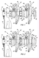
- FIG. 1 a Area of a knotter assembly 10 with a drive shaft 12th is shown, which has opposite end portions, the are stored in corresponding bearings 14, the transverse to spaced walls 16 of a baler frame one Rectangular baler or a square baler attached are.
- a plurality are identical Knotter drive assemblies or knotter units attached, of which only two are shown at 18 and 20, but it It should be clear that the total number of knot units usually in accordance with the size of the produced Bale varies, and the total number of loops of yarn around to wrap the bales would correspond.
- Each of the Knotter units 18 and 20 has a drive gear 22 and a support frame 24 which, like the Knoterbaumaschine, the be borne by him, only partially shown.
- the drive gears 22 have a hub with one, as this FIG. 1, short right hub region 26 and an elongated left hub region 28.
- the Drive gears 22 have a spring 30 to communicate with the Drive shaft 12 to rotate and relative to this axially to be able to move.
- the support frames 24 each have a slotted sleeve 32 with opposite halves on, around the left Hub portion 28 of the corresponding drive gear 22 releasably clamped, wherein the sleeve 32 sized such is that the hub portion 28 can rotate freely therein. It should be clear that the left hub area 28 each of the Drive gears 22 can be shortened, in which case the Cuff 32 each of the support frame 24 directly on the Drive shaft 12 would be provided to the drive shaft 12 to allow to freely rotate in the cuff 32.
- each support frame 24 each have a driven gear or a cam follower, the are arranged according to different To mesh tooth segments or to cam surfaces of the adjacent drive gear 22 attack, wherein a Section of a toothed segment is shown at 34.
- the knotter units 18 and 20 are along the drive shaft 12 spaced axially equidistant from each other. Rights and left, stop-forming shoulders 36 are of the Drive shaft 12 received and by a suitable Safety device in places left and right side of the Bale forming chamber (not shown) of the baler at the the knotter drive shaft 12 is used, held.
- a possible embodiment of the shoulder is this, from to provide separable halves, which by a pair of Screws are connected through holes in the halves, which are on opposite sides of the Knoter drive shaft 12 extend. It is understandable that the left shoulder 36, the only illustrated shoulder, through a shoulder formed on the drive shaft 12 is determined can be.
- each the drive gears 22 is a pair drilled and with a Provided threaded bores, in which a pair of adjusting elements 38, which serve as lifting or spacer screws are executed, can be recorded accordingly.
- a pair of adjusting elements 38 which serve as lifting or spacer screws are executed, can be recorded accordingly.
- On each adjustment member 38 is a self-locking nut executed fuse element 40 placed to its axial Set position in the associated threaded hole.
- one Securing element 40 can be used with a nose, the can be moved to the head of the Fuse element 40 comes in and out of contact to his To prevent movement once it is set.
- the heads the adjusting elements 38 of the drive gears 22 of the Knotter units 18 load on the left side of the Hub portion 28 of the drive gear 22 of the knotter unit 20th and the heads of the fuse elements 38 on the right side the boss portion 26 of the drive gear 22 of the knotter unit 20 loads on the left end side of the hub portion 28 of the Drive gear 22 of the next adjacent knotter unit etc ..
- the heads of the fuse elements 38 would axial end faces of the sleeve 32 of the support frame 24th loads.
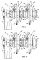
- the drive shaft 12 carries from left to right identical drive gears 22 ', different from the Drive gears 22 differ only in that the outer diameter of the boss portion 26 is too small to to contain enough material to allow holes to drill into and cut threads in to the Adjustment elements 38 record.
- a right end face of the spacer 42 acts with a left end face of the boss portion 28 'of the Drive gear 22 'of the knotter unit 20 together.
- a left End face of the spacer 42 has a countersink or a recess 44 in which a right end portion of the Hub portion 26 'of the drive gear 22' of the knotter unit 18 is recorded.
- Adjusting elements 38 The area of this left end face of The hub portion 26 ' is drilled and threaded provided to diametrically opposed threaded holes in which a pair formed as a spacer screws Adjusting elements 38 is screwed accordingly.
- the heads the adjusting elements 38 load on a right surface or End face of the drive gear 22 '.
- a similar one Spacer 42 and adjusting 38 are between the Drive gears 22 'of the knotter unit 20 and the next adjacent knotter unit to the right of the knotter unit 20 arranged accordingly.
- the spacer 42 sufficient material for attaching the Adjusting means 38 provides, which by acting over the spacer 42, the distance between the Knoterizien 18 and 20 'set. This Adjustment process is very similar to when the adjustment means 38 are arranged in the hubs of the drive gears 22.
- FIG. 3 in which a third Embodiment of the invention is shown, the Driving gears 22 'corresponding to those in Figure 2, but the spacers 42 are omitted.
- support frame 24 ' are provided, which differ from the Frame 24 differ in that they cuffs 32 ' having a larger réelle bemsser than the cuffs 32.
- a left end face of these cuffs 32 ' is in each case at diametrically opposite locations with Tapped holes and takes as appropriate Distance screws trained adjusting 38 ', which the Adjusting elements 38 same, but are longer, so this the distance between the sleeve 32 'and the right Spanning the end face of the drive gear 22 '.
- a fourth embodiment of Invention which has a plurality of drive gears 22 "similar to the drive gears 22 ', except that the right end portion of each hub portion 28 with a thread 46 is provided.
- the adjustment 48 has according to this embodiment, a spacer, the the spacer 42 of Figure 2 is similar in that he is a Has inner bore and on the right end of the Hub area 28 ", but instead slidable on the hub portion 28 "of the drive gear 22 ", the inner bore is in with one Thread 50 provided and cooperates with the thread 46, the on the outside of the right end portion of the boss portion
- matching surfaces (not shown) on both the spacer and the adjusting element 48 and on the securing element 52, on which during a distance adjustment a simpler Can attack wrench.
- adjustment elements 38, 38 'in the form of spacer screws a simple, effective Provide adjustment directly between adjacent drive gears on the drive shaft may be arranged, as shown in Figure 1, the via a spacer on the drive shaft between the Knoterüen arranged, as shown in Figure 2, or directly between the support frame and the Drive gear, as shown in Figure 3, can act.
Landscapes
- Life Sciences & Earth Sciences (AREA)
- Environmental Sciences (AREA)
- Preliminary Treatment Of Fibers (AREA)
- Basic Packing Technique (AREA)
- Jellies, Jams, And Syrups (AREA)
- Supports For Plants (AREA)
Abstract
Description
Claims (11)
- Knoteranordnung (10) mit einer Antriebswelle (12), einer Mehrzahl von auf dieser Antriebswelle (12) angebrachten Knotereinheiten (18, 20) mit jeweils einem Antriebszahnrad (22, 22', 22") mit einer Nabe (26, 28), welche auf die Antriebswelle (12) derart aufgesetzt ist, dass sie mit dieser rotieren und mit Bezug auf die Antriebswelle (12) in axialer Richtung bewegt werden kann, und einer Einstelleinrichtung, die eine axiale Lücke zwischen gegenüberliegenden Stirnflächen aneinander angrenzender Knotereinheiten (18, 20) derart einstellbar überspannt, dass sie die axiale Erstreckung der Lücke bestimmt, dadurch gekennzeichnet, dass die Einstelleinrichtung zumindest ein Einstellelement (38, 38', 48), durch dessen Hinein- bzw. Herausschrauben der axiale Abstand zwischen den Knotereinheiten (18, 20) verstellt werden kann, und ein Sicherungselement (40, 52) aufweist, mittels dem das Einstellelement lösbar festlegbar ist.
- Knoteranordnung nach Anspruch 1, dadurch gekennzeichnet, dass die Knotereinheit (18, 20) einen Tragrahmen (24) mit einer Hülse (32), die lose auf die Antriebswelle (12) und die Nabe aufgesetzt ist, aufweist.
- Knoteranordnung nach Anspruch 1 oder 2, dadurch gekennzeichnet, dass das Einstellelement (38, 38', 48) eine Distanzschraube aufweist bzw. als eine solche ausgebildet ist, die in eine der Stirnflächen eingeschraubt bzw. aus dieser herausgeschraubt werden kann, und einen Kopf aufweist, der mit der gegenüberliegenden Stirnflächen zusammenwirkt.
- Knoteranordnung nach einem oder mehreren der vorherigen Ansprüche, gekennzeichnet durch ein zweites Einstellelement (38, 38', 48), dass dem ersten Einstellelement (38, 38', 48) zumindest im Wesentlichen diametral gegenüberliegt und vorzugsweise als Distanzschraube ausgebildet ist bzw. eine solche aufweist.
- Knoteranordnung nach einem oder mehreren der vorherigen Ansprüche, dadurch gekennzeichnet, dass das Sicherungselement (40, 52) als eine selbstsichernde Mutter ausgebildet ist bzw. eine solche aufweist, die vorzugsweise mit wenigstens einem der Einstellelemente (38, 38', 48) zusammenwirkt.
- Knoteranordnung nach einem oder mehreren der vorherigen Ansprüche, dadurch gekennzeichnet, dass die Stirnflächen durch entsprechende Endflächen der Naben von Antriebszahnräder (22, 22', 22") angrenzender Knotereinheiten (18, 20) gebildet werden.
- Knoteranordnung nach einem oder mehreren der Ansprüche 2 bis 5, dadurch gekennzeichnet, dass die Stirnflächen entsprechend jeweils durch eine Stirnfläche des Antriebszahnrades (22, 22', 22 ") einer der Knotereinheiten (18, 20) und eine Endfläche der Manschette (32) des Tragrahmens (24) eines angrenzenden Tragrahmens (24) gebildet werden, wobei das Sicherungselement (40, 52) wenigstens eine Distanzschraube aufweist bzw. als eine solche ausgebildet ist, welche in den Endbereich der Manschette (32) einschraubbar bzw. aus diesem herausschraubbar und deren Kopf mit der Stirnfläche des Antriebszahnrades (22, 22', 22 ") zusammenwirkt.
- Knoteranordnung nach einem oder mehreren der Ansprüche 1 bis 6, dadurch gekennzeichnet, dass das Einstellelement (38, 38', 48) eine auf der Antriebswelle (12) zwischen angrenzenden Knotereinheiten (18, 20) aufgenommenen Abstandhalter (42) und wenigstens eine Distanzschraube aufweist, die in eine axiale Stirnfläche des Abstandhalters (42) eingeschraubt bzw. aus dieser herausgeschraubt werden kann.
- Knoteranordnung nach Anspruch 8, dadurch gekennzeichnet, dass der Abstandhalter (42) sich radial über die Naben der angrenzenden Antriebszahnräder (22, 22', 22 ") hinaus erstreckt und die Distanzschraube radial außerhalb und parallel zu den Naben angeordnet ist.
- Knoteranordnung nach Anspruch 1, dadurch gekennzeichnet, dass das Einstellelement (38, 38', 48) einen Abstandhalter aufweist oder als ein solcher ausgebildet ist, der auf der Antriebswelle (12) zwischen angrenzenden Knotereinheiten (18, 20) angeordnet ist, eine der Naben der angrenzenden Antriebszahnräder (22, 22', 22") ein Außengewinde (46) aufweist und der Abstandhalter ein Innengewinde (50) aufweist, dass durch das Außengewinde (46) aufgenommen werden kann.
- Knoteranordnung nach Anspruch 10, dadurch gekennzeichnet, dass das Sicherungselement (20, 52) eine Kontermutter aufweist oder durch eine solche gebildet wird, die auf dem Außengewinde (46) angeordnet ist.
Applications Claiming Priority (2)
| Application Number | Priority Date | Filing Date | Title |
|---|---|---|---|
| US719096 | 2003-11-21 | ||
| US10/719,096 US6957835B2 (en) | 2003-11-21 | 2003-11-21 | Device for adjusting the space between adjacent knotter assemblies on a knotter drive shaft |
Publications (2)
| Publication Number | Publication Date |
|---|---|
| EP1532859A1 true EP1532859A1 (de) | 2005-05-25 |
| EP1532859B1 EP1532859B1 (de) | 2008-02-13 |
Family
ID=34435798
Family Applications (1)
| Application Number | Title | Priority Date | Filing Date |
|---|---|---|---|
| EP04105844A Expired - Lifetime EP1532859B1 (de) | 2003-11-21 | 2004-11-17 | Knoteranordnung |
Country Status (4)
| Country | Link |
|---|---|
| US (1) | US6957835B2 (de) |
| EP (1) | EP1532859B1 (de) |
| AT (1) | ATE385681T1 (de) |
| DE (1) | DE502004006178D1 (de) |
Cited By (3)
| Publication number | Priority date | Publication date | Assignee | Title |
|---|---|---|---|---|
| WO2011054360A1 (de) * | 2009-11-03 | 2011-05-12 | Rasspe Systemtechnik Gmbh & Co. Kg | Doppelknoten-garnknoter-einheit fur grosspackenpressen mit mehreren auf einer knoter-antriebswelle zusammgefassten doppelknoten-garnknotern |
| WO2013185832A3 (de) * | 2012-06-14 | 2014-05-15 | Rasspe Systemtechnik Gmbh & Co. Kg | Garnknoter |
| CN105638119A (zh) * | 2015-12-07 | 2016-06-08 | 江苏大学 | 一种双齿盘驱动打结器 |
Families Citing this family (12)
| Publication number | Priority date | Publication date | Assignee | Title |
|---|---|---|---|---|
| DE102009032800B4 (de) * | 2009-07-10 | 2011-07-28 | Maschinenfabrik Bernard Krone GmbH, 48480 | Großballenpresse |
| US9045245B2 (en) | 2010-03-04 | 2015-06-02 | L&P Property Management Company | Knotter assembly |
| US8397632B2 (en) * | 2010-03-04 | 2013-03-19 | L & P Property Management Company | Knotter assembly |
| US10684595B2 (en) | 2013-09-04 | 2020-06-16 | Accent Wire Holdings, LLC | Control user interface for tying system |
| US9278772B2 (en) | 2014-02-20 | 2016-03-08 | L&P Property Management Company | Combination wire and plastic strapping device |
| US10351274B2 (en) | 2014-02-20 | 2019-07-16 | Accent Packaging Inc. | Combination wire and plastic strapping device |
| US11040789B2 (en) | 2014-02-20 | 2021-06-22 | Accent Wire Holdings Llc | Combination wire and plastic strapping device |
| US9359094B2 (en) | 2014-03-10 | 2016-06-07 | L & P Property Management Company | Gripping mechanism |
| WO2016155364A1 (zh) * | 2015-04-03 | 2016-10-06 | 江苏大学 | 一种双齿盘驱动打结器 |
| CN105191589B (zh) * | 2015-10-20 | 2017-03-01 | 江苏大学 | 一种打结器用双动卡爪式强制脱扣机构 |
| US11606908B2 (en) | 2020-07-01 | 2023-03-21 | Deere & Company | Intermittent knotter gear |
| US12302797B1 (en) * | 2023-11-07 | 2025-05-20 | Great Plains Manufacturing, Inc. | Locking mechanism for knotter assemblies |
Citations (4)
| Publication number | Priority date | Publication date | Assignee | Title |
|---|---|---|---|---|
| US3418014A (en) * | 1967-08-16 | 1968-12-24 | Sperry Rand Corp | Knotter clamp means for baler |
| FR2115768A5 (de) * | 1970-11-21 | 1972-07-07 | Rasspe Pd Sohne | |
| US4022121A (en) * | 1976-08-18 | 1977-05-10 | Sperry Rand Corporation | Adjustment cams for removing end play from tying mechanism on a baler |
| EP0956761A1 (de) * | 1998-04-30 | 1999-11-17 | Case Harvesting Systems GmbH | Knüpfapparat für Ballenpressen |
Family Cites Families (4)
| Publication number | Priority date | Publication date | Assignee | Title |
|---|---|---|---|---|
| US4540199A (en) * | 1982-09-01 | 1985-09-10 | Neill David C | Jack bolt assembly |
| US4783119A (en) * | 1987-09-30 | 1988-11-08 | Moses Rodney D | Lightweight adjustable bicycle saddle mount |
| US4927305A (en) * | 1988-09-02 | 1990-05-22 | Peterson Charles D | Tightening device for threaded connectors |
| DE69937246T2 (de) * | 1998-06-10 | 2008-07-03 | Steinbock Machinery Co. | Verspannschrauben für spanner mit mehreren verspannschrauben |
-
2003
- 2003-11-21 US US10/719,096 patent/US6957835B2/en not_active Expired - Lifetime
-
2004
- 2004-11-17 AT AT04105844T patent/ATE385681T1/de not_active IP Right Cessation
- 2004-11-17 EP EP04105844A patent/EP1532859B1/de not_active Expired - Lifetime
- 2004-11-17 DE DE502004006178T patent/DE502004006178D1/de not_active Expired - Lifetime
Patent Citations (4)
| Publication number | Priority date | Publication date | Assignee | Title |
|---|---|---|---|---|
| US3418014A (en) * | 1967-08-16 | 1968-12-24 | Sperry Rand Corp | Knotter clamp means for baler |
| FR2115768A5 (de) * | 1970-11-21 | 1972-07-07 | Rasspe Pd Sohne | |
| US4022121A (en) * | 1976-08-18 | 1977-05-10 | Sperry Rand Corporation | Adjustment cams for removing end play from tying mechanism on a baler |
| EP0956761A1 (de) * | 1998-04-30 | 1999-11-17 | Case Harvesting Systems GmbH | Knüpfapparat für Ballenpressen |
Cited By (7)
| Publication number | Priority date | Publication date | Assignee | Title |
|---|---|---|---|---|
| WO2011054360A1 (de) * | 2009-11-03 | 2011-05-12 | Rasspe Systemtechnik Gmbh & Co. Kg | Doppelknoten-garnknoter-einheit fur grosspackenpressen mit mehreren auf einer knoter-antriebswelle zusammgefassten doppelknoten-garnknotern |
| US8590945B2 (en) | 2009-11-03 | 2013-11-26 | Rasspe Systemtechnik GMBH & Co., KG | Double-knot twine-knotter unit for large bale presses with a plurality of double-knot twine-knotters assembled on one knotter driveshaft |
| CN102665387B (zh) * | 2009-11-03 | 2016-02-24 | 腊斯佩系统技术有限两合公司 | 双结式捆绳打结器单元 |
| EA023784B1 (ru) * | 2009-11-03 | 2016-07-29 | Расспе Зюстемтехник Гмбх Унд Ко.Кг | Блок узловязателей двойного узловязания шпагата и крупногабаритный упаковочный пресс с обвязкой шпагатом, содержащий множество узловязателей двойного узловязания шпагата, объединенных на одном валу привода узловязателей |
| WO2013185832A3 (de) * | 2012-06-14 | 2014-05-15 | Rasspe Systemtechnik Gmbh & Co. Kg | Garnknoter |
| US9832932B2 (en) | 2012-06-14 | 2017-12-05 | Rasspe Systemtechnik GmbH | Twine knotter |
| CN105638119A (zh) * | 2015-12-07 | 2016-06-08 | 江苏大学 | 一种双齿盘驱动打结器 |
Also Published As
| Publication number | Publication date |
|---|---|
| EP1532859B1 (de) | 2008-02-13 |
| US6957835B2 (en) | 2005-10-25 |
| ATE385681T1 (de) | 2008-03-15 |
| US20050110276A1 (en) | 2005-05-26 |
| DE502004006178D1 (de) | 2008-03-27 |
Similar Documents
| Publication | Publication Date | Title |
|---|---|---|
| EP1532859B1 (de) | Knoteranordnung | |
| EP1020652B1 (de) | Verbindungselement für zwei Maschinen- oder Bauteile, insbesondere Pass-Dehnschraube, Pass-Gewindebolzen o.dgl. | |
| ZA200102485B (en) | Device for arranging, clamping or contracting a ring-shaped securing mechanism. | |
| DE1944805A1 (de) | Verschraubung | |
| DE60204741T2 (de) | Anordnung von Pneumatikmodulen | |
| WO1995023926A1 (de) | Spannanordnung mit einem konusspannbolzen | |
| DE2929335C2 (de) | Vorrichtung zum axialen Einstellen eines Walzenzapfens einer Walzwerks-Walze | |
| DE69607462T2 (de) | Selbstsichernde Mutter | |
| DE3817893C2 (de) | ||
| WO2015173182A1 (de) | Ringförmige spannmutter für einen zuganker | |
| DE102017212551A1 (de) | Stator und Elektromotor | |
| EP3141639B1 (de) | Befestigungsvorrichtung für kämmelemente an einem rundkamm | |
| DE2804009A1 (de) | Ueberlastungsschutzeinrichtung | |
| DE3344133C2 (de) | ||
| DE3220743C2 (de) | Einrichtung zum Verzurren von Containern | |
| EP0956761A1 (de) | Knüpfapparat für Ballenpressen | |
| DE1961980C3 (de) | Nabenbefestigung | |
| DE3204919C1 (de) | Kugelgewindetrieb | |
| DE3102129A1 (de) | Befestigunselement mit drehmomentbegrenzer | |
| DE2736649A1 (de) | Verschnuervorrichtung fuer eine ballenpresse | |
| DE4316808C2 (de) | Spannstück für Rohrelemente | |
| DE3130229C2 (de) | Mehrschneidenwerkzeug | |
| DE19611805C2 (de) | Bolzenverbindung | |
| DE850110C (de) | Rollfilmentwicklungsspule mit veraenderbarem Spulentellerabstand | |
| EP0407761A2 (de) | Steuerwelle |
Legal Events
| Date | Code | Title | Description |
|---|---|---|---|
| PUAI | Public reference made under article 153(3) epc to a published international application that has entered the european phase |
Free format text: ORIGINAL CODE: 0009012 |
|
| AK | Designated contracting states |
Kind code of ref document: A1 Designated state(s): AT BE BG CH CY CZ DE DK EE ES FI FR GB GR HU IE IS IT LI LU MC NL PL PT RO SE SI SK TR |
|
| AX | Request for extension of the european patent |
Extension state: AL HR LT LV MK YU |
|
| 17P | Request for examination filed |
Effective date: 20051125 |
|
| AKX | Designation fees paid |
Designated state(s): AT BE BG CH CY CZ DE DK EE ES FI FR GB GR HU IE IS IT LI LU MC NL PL PT RO SE SI SK TR |
|
| GRAP | Despatch of communication of intention to grant a patent |
Free format text: ORIGINAL CODE: EPIDOSNIGR1 |
|
| GRAS | Grant fee paid |
Free format text: ORIGINAL CODE: EPIDOSNIGR3 |
|
| GRAA | (expected) grant |
Free format text: ORIGINAL CODE: 0009210 |
|
| AK | Designated contracting states |
Kind code of ref document: B1 Designated state(s): AT BE BG CH CY CZ DE DK EE ES FI FR GB GR HU IE IS IT LI LU MC NL PL PT RO SE SI SK TR |
|
| REG | Reference to a national code |
Ref country code: GB Ref legal event code: FG4D Free format text: NOT ENGLISH |
|
| REG | Reference to a national code |
Ref country code: CH Ref legal event code: EP |
|
| REG | Reference to a national code |
Ref country code: IE Ref legal event code: FG4D Free format text: LANGUAGE OF EP DOCUMENT: GERMAN |
|
| REF | Corresponds to: |
Ref document number: 502004006178 Country of ref document: DE Date of ref document: 20080327 Kind code of ref document: P |
|
| PG25 | Lapsed in a contracting state [announced via postgrant information from national office to epo] |
Ref country code: FI Free format text: LAPSE BECAUSE OF FAILURE TO SUBMIT A TRANSLATION OF THE DESCRIPTION OR TO PAY THE FEE WITHIN THE PRESCRIBED TIME-LIMIT Effective date: 20080213 Ref country code: ES Free format text: LAPSE BECAUSE OF FAILURE TO SUBMIT A TRANSLATION OF THE DESCRIPTION OR TO PAY THE FEE WITHIN THE PRESCRIBED TIME-LIMIT Effective date: 20080524 Ref country code: IS Free format text: LAPSE BECAUSE OF FAILURE TO SUBMIT A TRANSLATION OF THE DESCRIPTION OR TO PAY THE FEE WITHIN THE PRESCRIBED TIME-LIMIT Effective date: 20080613 |
|
| ET | Fr: translation filed | ||
| PG25 | Lapsed in a contracting state [announced via postgrant information from national office to epo] |
Ref country code: PL Free format text: LAPSE BECAUSE OF FAILURE TO SUBMIT A TRANSLATION OF THE DESCRIPTION OR TO PAY THE FEE WITHIN THE PRESCRIBED TIME-LIMIT Effective date: 20080213 Ref country code: SI Free format text: LAPSE BECAUSE OF FAILURE TO SUBMIT A TRANSLATION OF THE DESCRIPTION OR TO PAY THE FEE WITHIN THE PRESCRIBED TIME-LIMIT Effective date: 20080213 |
|
| REG | Reference to a national code |
Ref country code: IE Ref legal event code: FD4D |
|
| PG25 | Lapsed in a contracting state [announced via postgrant information from national office to epo] |
Ref country code: PT Free format text: LAPSE BECAUSE OF FAILURE TO SUBMIT A TRANSLATION OF THE DESCRIPTION OR TO PAY THE FEE WITHIN THE PRESCRIBED TIME-LIMIT Effective date: 20080714 Ref country code: SE Free format text: LAPSE BECAUSE OF FAILURE TO SUBMIT A TRANSLATION OF THE DESCRIPTION OR TO PAY THE FEE WITHIN THE PRESCRIBED TIME-LIMIT Effective date: 20080513 Ref country code: SK Free format text: LAPSE BECAUSE OF FAILURE TO SUBMIT A TRANSLATION OF THE DESCRIPTION OR TO PAY THE FEE WITHIN THE PRESCRIBED TIME-LIMIT Effective date: 20080213 Ref country code: CZ Free format text: LAPSE BECAUSE OF FAILURE TO SUBMIT A TRANSLATION OF THE DESCRIPTION OR TO PAY THE FEE WITHIN THE PRESCRIBED TIME-LIMIT Effective date: 20080213 Ref country code: DK Free format text: LAPSE BECAUSE OF FAILURE TO SUBMIT A TRANSLATION OF THE DESCRIPTION OR TO PAY THE FEE WITHIN THE PRESCRIBED TIME-LIMIT Effective date: 20080213 Ref country code: IE Free format text: LAPSE BECAUSE OF FAILURE TO SUBMIT A TRANSLATION OF THE DESCRIPTION OR TO PAY THE FEE WITHIN THE PRESCRIBED TIME-LIMIT Effective date: 20080213 |
|
| PG25 | Lapsed in a contracting state [announced via postgrant information from national office to epo] |
Ref country code: RO Free format text: LAPSE BECAUSE OF FAILURE TO SUBMIT A TRANSLATION OF THE DESCRIPTION OR TO PAY THE FEE WITHIN THE PRESCRIBED TIME-LIMIT Effective date: 20080213 |
|
| PLBE | No opposition filed within time limit |
Free format text: ORIGINAL CODE: 0009261 |
|
| STAA | Information on the status of an ep patent application or granted ep patent |
Free format text: STATUS: NO OPPOSITION FILED WITHIN TIME LIMIT |
|
| 26N | No opposition filed |
Effective date: 20081114 |
|
| PGFP | Annual fee paid to national office [announced via postgrant information from national office to epo] |
Ref country code: NL Payment date: 20081124 Year of fee payment: 5 |
|
| PGFP | Annual fee paid to national office [announced via postgrant information from national office to epo] |
Ref country code: IT Payment date: 20081125 Year of fee payment: 5 |
|
| PG25 | Lapsed in a contracting state [announced via postgrant information from national office to epo] |
Ref country code: EE Free format text: LAPSE BECAUSE OF FAILURE TO SUBMIT A TRANSLATION OF THE DESCRIPTION OR TO PAY THE FEE WITHIN THE PRESCRIBED TIME-LIMIT Effective date: 20080213 Ref country code: BG Free format text: LAPSE BECAUSE OF FAILURE TO SUBMIT A TRANSLATION OF THE DESCRIPTION OR TO PAY THE FEE WITHIN THE PRESCRIBED TIME-LIMIT Effective date: 20080513 |
|
| PG25 | Lapsed in a contracting state [announced via postgrant information from national office to epo] |
Ref country code: MC Free format text: LAPSE BECAUSE OF NON-PAYMENT OF DUE FEES Effective date: 20081130 |
|
| REG | Reference to a national code |
Ref country code: CH Ref legal event code: PL |
|
| GBPC | Gb: european patent ceased through non-payment of renewal fee |
Effective date: 20081117 |
|
| PG25 | Lapsed in a contracting state [announced via postgrant information from national office to epo] |
Ref country code: CY Free format text: LAPSE BECAUSE OF FAILURE TO SUBMIT A TRANSLATION OF THE DESCRIPTION OR TO PAY THE FEE WITHIN THE PRESCRIBED TIME-LIMIT Effective date: 20080213 |
|
| PGFP | Annual fee paid to national office [announced via postgrant information from national office to epo] |
Ref country code: BE Payment date: 20090128 Year of fee payment: 5 |
|
| PG25 | Lapsed in a contracting state [announced via postgrant information from national office to epo] |
Ref country code: LI Free format text: LAPSE BECAUSE OF NON-PAYMENT OF DUE FEES Effective date: 20081130 Ref country code: CH Free format text: LAPSE BECAUSE OF NON-PAYMENT OF DUE FEES Effective date: 20081130 |
|
| PG25 | Lapsed in a contracting state [announced via postgrant information from national office to epo] |
Ref country code: GB Free format text: LAPSE BECAUSE OF NON-PAYMENT OF DUE FEES Effective date: 20081117 |
|
| PG25 | Lapsed in a contracting state [announced via postgrant information from national office to epo] |
Ref country code: AT Free format text: LAPSE BECAUSE OF NON-PAYMENT OF DUE FEES Effective date: 20081117 |
|
| BERE | Be: lapsed |
Owner name: DEERE & CY Effective date: 20091130 |
|
| REG | Reference to a national code |
Ref country code: NL Ref legal event code: V1 Effective date: 20100601 |
|
| PG25 | Lapsed in a contracting state [announced via postgrant information from national office to epo] |
Ref country code: HU Free format text: LAPSE BECAUSE OF FAILURE TO SUBMIT A TRANSLATION OF THE DESCRIPTION OR TO PAY THE FEE WITHIN THE PRESCRIBED TIME-LIMIT Effective date: 20080814 Ref country code: LU Free format text: LAPSE BECAUSE OF NON-PAYMENT OF DUE FEES Effective date: 20081117 |
|
| PG25 | Lapsed in a contracting state [announced via postgrant information from national office to epo] |
Ref country code: TR Free format text: LAPSE BECAUSE OF FAILURE TO SUBMIT A TRANSLATION OF THE DESCRIPTION OR TO PAY THE FEE WITHIN THE PRESCRIBED TIME-LIMIT Effective date: 20080213 |
|
| PG25 | Lapsed in a contracting state [announced via postgrant information from national office to epo] |
Ref country code: GR Free format text: LAPSE BECAUSE OF FAILURE TO SUBMIT A TRANSLATION OF THE DESCRIPTION OR TO PAY THE FEE WITHIN THE PRESCRIBED TIME-LIMIT Effective date: 20080514 Ref country code: BE Free format text: LAPSE BECAUSE OF NON-PAYMENT OF DUE FEES Effective date: 20091130 Ref country code: NL Free format text: LAPSE BECAUSE OF NON-PAYMENT OF DUE FEES Effective date: 20100601 |
|
| PG25 | Lapsed in a contracting state [announced via postgrant information from national office to epo] |
Ref country code: IT Free format text: LAPSE BECAUSE OF NON-PAYMENT OF DUE FEES Effective date: 20091117 |
|
| REG | Reference to a national code |
Ref country code: FR Ref legal event code: PLFP Year of fee payment: 12 |
|
| REG | Reference to a national code |
Ref country code: FR Ref legal event code: PLFP Year of fee payment: 13 |
|
| REG | Reference to a national code |
Ref country code: FR Ref legal event code: PLFP Year of fee payment: 14 |
|
| PGFP | Annual fee paid to national office [announced via postgrant information from national office to epo] |
Ref country code: FR Payment date: 20171127 Year of fee payment: 14 |
|
| PG25 | Lapsed in a contracting state [announced via postgrant information from national office to epo] |
Ref country code: FR Free format text: LAPSE BECAUSE OF NON-PAYMENT OF DUE FEES Effective date: 20181130 |
|
| PGFP | Annual fee paid to national office [announced via postgrant information from national office to epo] |
Ref country code: DE Payment date: 20191021 Year of fee payment: 16 |
|
| REG | Reference to a national code |
Ref country code: DE Ref legal event code: R119 Ref document number: 502004006178 Country of ref document: DE |
|
| PG25 | Lapsed in a contracting state [announced via postgrant information from national office to epo] |
Ref country code: DE Free format text: LAPSE BECAUSE OF NON-PAYMENT OF DUE FEES Effective date: 20210601 |