EP1532349B1 - Elektrisch betätigtes ventil zur stromregelung von hydraulikflüssigkeit - Google Patents
Elektrisch betätigtes ventil zur stromregelung von hydraulikflüssigkeit Download PDFInfo
- Publication number
- EP1532349B1 EP1532349B1 EP03771201A EP03771201A EP1532349B1 EP 1532349 B1 EP1532349 B1 EP 1532349B1 EP 03771201 A EP03771201 A EP 03771201A EP 03771201 A EP03771201 A EP 03771201A EP 1532349 B1 EP1532349 B1 EP 1532349B1
- Authority
- EP
- European Patent Office
- Prior art keywords
- spool
- fluid
- valve
- fluid conduit
- flow
- Prior art date
- Legal status (The legal status is an assumption and is not a legal conclusion. Google has not performed a legal analysis and makes no representation as to the accuracy of the status listed.)
- Expired - Lifetime
Links
Images
Classifications
-
- F—MECHANICAL ENGINEERING; LIGHTING; HEATING; WEAPONS; BLASTING
- F01—MACHINES OR ENGINES IN GENERAL; ENGINE PLANTS IN GENERAL; STEAM ENGINES
- F01L—CYCLICALLY OPERATING VALVES FOR MACHINES OR ENGINES
- F01L1/00—Valve-gear or valve arrangements, e.g. lift-valve gear
- F01L1/46—Component parts, details, or accessories, not provided for in preceding subgroups
-
- F—MECHANICAL ENGINEERING; LIGHTING; HEATING; WEAPONS; BLASTING
- F01—MACHINES OR ENGINES IN GENERAL; ENGINE PLANTS IN GENERAL; STEAM ENGINES
- F01L—CYCLICALLY OPERATING VALVES FOR MACHINES OR ENGINES
- F01L9/00—Valve-gear or valve arrangements actuated non-mechanically
- F01L9/10—Valve-gear or valve arrangements actuated non-mechanically by fluid means, e.g. hydraulic
-
- Y—GENERAL TAGGING OF NEW TECHNOLOGICAL DEVELOPMENTS; GENERAL TAGGING OF CROSS-SECTIONAL TECHNOLOGIES SPANNING OVER SEVERAL SECTIONS OF THE IPC; TECHNICAL SUBJECTS COVERED BY FORMER USPC CROSS-REFERENCE ART COLLECTIONS [XRACs] AND DIGESTS
- Y10—TECHNICAL SUBJECTS COVERED BY FORMER USPC
- Y10T—TECHNICAL SUBJECTS COVERED BY FORMER US CLASSIFICATION
- Y10T137/00—Fluid handling
- Y10T137/8593—Systems
- Y10T137/86493—Multi-way valve unit
Definitions
- the present invention relates to an electrically operated valve for controlling flow of hydraulic fluid.
- valves for controlling flow of hydraulic fluid to actuators attached to engine valves of an internal combustion engine. It has often been suggested in the past that in an internal combustion engine a mechanical cam shaft could be replaced by a series of hydraulic actuators which would open and close the engine valve. The hydraulic actuators are controlled by controlling the flow of hydraulic fluid to them.
- Various different arrangements of valves such as known from GB-A-1 324 456 have been proposed for the control of hydraulic fluid. However, there is still a need for a simple and cost-effective valve arrangement and this issue is addressed by the present invention.
- the present invention provides an electrically operated valve for controlling flow of hydraulic fluid comprising:
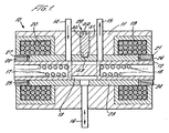
- a first fluid conduit 14 extends through the valve housing 11 and connects the spool chamber 13 with a source of pressure.
- a second fluid conduit 15 extends through the valve housing 11 and connects the spool chamber 13 with a return line for returning hydraulic fluid to a reservoir.
- a third fluid conduit 16 extends through the valve housing 11 and connects the valve 10 to whatever apparatus receives the flow of hydraulic fluid controlled by the valve 10.
- Two electric coils 19 and 20 surround the ends of the spool 12. Surrounding each end of the spool 12 there is provided an armature 21 and 22.
- the spool 12 is surrounded by a sleeve 23.
- This sleeve 23 has two annular end surfaces 24 and 25.
- the annular end surface 24 faces an annular end surface 26 of the armature 21.
- the annular surface 25 faces an annular surface 27 of the armature 22.
- the fluid conduit 16 is permanently open to the spool chamber 13.
- a null adjust mechanism 28 This comprises an externally threaded rotatable screw 50 provided in a threaded bore 51 in the valve housing 11.
- a hexagonal socket 52 is provided at the tip of the screw 50 and can be engaged and rotated by an Allen key.
- An eccentric cam 53 extends downwardly from the screw 50 and acts on a reaction surface provided on the sleeve 23. On rotating the cam 53 it is possible to slide the sleeve 23 within the valve housing 11.
- valve 10 By having a high pre-load applied on the spool 12 in its resting position by both the spring 17 and the spring 18, with the forces applied by the springs cancelled out by each other, it is possible to set a low spring rate and to determine how much force must be applied to move the spool valve 12 from its centralised position.
- This feature allows the valve to be used easily as a metering valve, because the current flowing through each of the electrical coils 20 or 21 can be adjusted to give a variable displacement of the valve spool 12, a variable degree of opening of the ports in the sleeve 23 and therefore a variable rate of flow through the valve 10.
- the valve 10 could operate as a switching valve, moving only between extreme positions by applying high value square-wave signals to the coils 19 and 20.
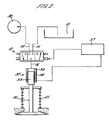
- the valve 10 can be seen represented schematically.
- the pressure line 14 is shown connected to a pump 30 and the return line 15 is shown connected to a reservoir 31.
- the line 16 is shown connected to an actuator 32.
- the actuator 32 comprises a piston 33 movable in a cylinder defined by a sleeve 34. Piston 33 and the sleeve 34 define together a variable volume chamber 35 which receives hydraulic fluid via the line 16.
- a position sensor 36 is built into the sleeve 34 and provides a feed back signal to an electronic controller 37.
- the electronic controller 37 uses the feedback signal along with other received parameters to provide a control signal which is relayed to the valve 10. As explained before, the control signal will be used to apply a current to one of the two coils 20 and 19.
- an engine valve 40 of an internal combustion engine e.g. an inlet or an exhaust valve
- valve spring 41 acting on the engine valve 40 can force the piston 33 to reduce in volume the chamber defined between piston 33 and sleeve 34, with the dispelled fluid being relayed via the valve 10 to the reservoir 31.
- the electronic controller 37 is part of a closed-loop feedback system which controls the position of the engine valve 40.
- the electronic controller 37 will send a demand signal to the valve 10 in the expectation that this will result in a position (and perhaps a rate of change of position) of the piston 33 and therefore the engine valve 40.
- the displacement transducer 36 will provide a signal which can be used to generate an error signal so that the electronic controller 37 can adjust the control signal it sends to the valve 10.
- feedback signal is important since the provision of a closed loop feedback system can provide for adaptive control, with the electronic controller making adjustments during the life of an engine to account for wear of components in the engine.
- the armatures 21, 22 are movable within the electric coils 19, 20 they could be formed as radially extending plates each with a surface facing an opposed end face of a coil 19, 20 (either an inboard or an outboard end face of a coil).
- the housing 11 would be provided with suitable chambers adjacent the coils 19, 20 in which the radially extending armatures could move.
- the springs 17, 18 are shown within bores in the spool 17, they could be mounted externally of the spool (perhaps in the spool chamber) if more conveniently.
- the rate of opening of the valve 40 and the rate of closing of the valve 40 can be controlled by controlling the rate of flow of fluid through the valve 10.
Landscapes
- Engineering & Computer Science (AREA)
- Mechanical Engineering (AREA)
- General Engineering & Computer Science (AREA)
- Magnetically Actuated Valves (AREA)
- Fluid-Driven Valves (AREA)
- Valve Device For Special Equipments (AREA)
- Servomotors (AREA)
- Multiple-Way Valves (AREA)
Claims (8)
- Elektrisch betätigtes Ventil zum Steuern des Durchflusses von Hydraulikfluid, wobei das Ventil Folgendes umfasst:ein Ventilgehäuse;einen Steuerschieber, der in einer Steuerschieberkammer in dem Ventilgehäuse gleiten kann;einen ersten Fluidkanal, der sich durch das Ventilgehäuse hindurch erstreckt, um die Steuerschieberkammer mit einer Quelle eines druckbeaufschlagten Fluids zu verbinden;einen zweiten Fluidkanal, der sich durch das Ventilgehäuse hindurch erstreckt, um die Steuerschieberkammer mit einem Fluidvorratsbehälter zu verbinden; undeinen dritten Fluidkanal in Strömungsverbindung mit der Steuerschieberkammer, der Fluid an eine Vorrichtung abgibt oder Fluid von einer Vorrichtung empfängt, die den durch das Ventil gesteuerten Hydraulikfluidfluss nutzt; wobei:dadurch gekennzeichnet, dass:der Steuerschieber durch ein Paar gegenüberliegender Federn in eine Ruheposition vorgespannt wird;der Steuerschieber in seiner Ruheposition den ersten und den zweiten Fluidkanal von der Steuerschieberkammer absperrt und dadurch verhindert, dass Fluid zu und von dem dritten Fluidkanal fließt;das Ventil eine erste elektrische Spule aufweist, die einem ersten Ende des Steuerschiebers zugeordnet ist und die aktiviert werden kann, um den Steuerschieber aus seiner Ruheposition zu verschieben, um den ersten Fluidkanal zu der Steuerschieberkammer zu öffnen, während der zweite Fluidkanal geschlossen gehalten wird, um es dadurch zu ermöglichen, dass druckbeaufschlagtes Fluid von dem ersten Fluidkanal zu dem dritten Fluidkanal fließt; unddas Ventil eine zweite elektrische Spule aufweist, die einem zweiten Ende des Steuerschiebers zugeordnet ist und die aktiviert werden kann, um den Steuerschieber aus seiner Ruheposition zu verschieben, um den zweiten Fluidkanal zu der Steuerschieberkammer zu öffnen, während der erste Fluidkanal geschlossen gehalten wird, um es dadurch zu ermöglichen, dass Fluid von dem dritten Fluidkanal zu dem zweiten Fluidkanal fließt.
- Elektrisch betätigtes Ventil nach Anspruch 1, wobei das Paar gegenüberliegender Federn jeweils eine Kraft an den Steuerschieber anlegt, wenn sich das Steuerschieberventil in seiner Ruheposition befindet.
- Elektrisch betätigtes Ventil nach Anspruch 1 oder Anspruch 2, wobei eine Hülse den Steuerschieber umgibt und die Steuerschieberkammer definiert, in der der Steuerschieber gleiten kann, wobei die Hülse eine erste Durchflussöffnung aufweist, durch die der erste Fluidkanal mit der Steuerschieberkammer in Strömungsverbindung steht, eine zweite Durchflussöffnung aufweist, durch die der zweite Fluidkanal in Strömungsverbindung mit der Steuerschieberkammer steht, und eine dritte Durchflussöffnung aufweist, durch die der dritte Fluidkanal in Strömungsverbindung mit der Steuerschieberkammer steht, und wobei das Ventil einen Justiermechanismus aufweist, um die Hülse relativ zu dem Ventilgehäuse zu verschieben.
- Elektrisch betätigtes Ventil nach Anspruch 3, wobei der Justiermechanismus einen drehbaren Nocken umfasst, der eine an der Hülse befindliche Reaktionsfläche in Eingriff nimmt.
- Elektrisch betätigtes Ventil nach einem der vorangehenden Ansprüche, wobei an dem Steuerschieber eine Armatur montiert ist, die das erste Ende des Steuerschiebers umgibt und innerhalb der ersten elektrischen Spule verschiebbar ist, und an dem Steuerschieber eine Armatur montiert ist, die das zweite Ende des Steuerschiebers umgibt und innerhalb der zweiten elektrischen Spule verschiebbar ist.
- Verfahren zum Betätigen des elektrisch betätigten Ventils nach einem der vorangehenden Ansprüche, wobei das Verfahren Folgendes umfasst:Auswählen zwischen der ersten und der zweiten Spule und Aktivieren der ersten elektrischen Spule, wenn druckbeaufschlagtes Fluid zu der Vorrichtung, die den Hydraulikfluidfluss nutzt, weitergegeben werden soll, und Aktivieren der zweiten elektrischen Spule, wenn Fluid aus der Vorrichtung, die den Hydraulikfluidfluss nutzt, in den Vorratsbehälter zurückgeführt werden soll; undSteuern des Stroms durch jede elektrische Spule und/oder der Spannung an jeder elektrischen Spule, wenn sie aktiviert wird, um die Strömungsrate des Fluids durch das Ventil hindurch zu steuern.
- Motorventilbetätigungssystem, das Folgendes umfasst:einen Aktuator, der auf ein Motorventil wirkt und vorgeschoben werden kann, um das Motorventil zu öffnen, und zurückgezogen werden kann, damit sich das Motorventil unter der Wirkung einer Motorventilfeder schließen kann;ein elektrisch betätigtes Ventil nach einem der vorangehenden Ansprüche, das dem Fluss von Hydraulikfluid zu und von dem Aktuator steuert; undeine elektronische Steuereinheit zum Steuern des Aktuators.
- Motorventilbetätigungssystem nach Anspruch 7, wobei:der Aktuator einen Kolben umfasst, der sich in einem Zylinder bewegen kann;das System außerdem einen Positionsmesswandler umfasst, der ein Positionssignal erzeugt, das die Position des Kolbens anzeigt; unddie elektronische Steuereinheit das Positionssignal benutzt, um ein Fehlersignal zu erzeugen, das für eine Regelkreissteuerung des Aktuators verwendet wird.
Applications Claiming Priority (3)
| Application Number | Priority Date | Filing Date | Title |
|---|---|---|---|
| GB0217642 | 2002-07-30 | ||
| GB0217642A GB2391288B (en) | 2002-07-30 | 2002-07-30 | An electrically operated valve for controlling flow of hydraulic fluid |
| PCT/GB2003/003301 WO2004011781A1 (en) | 2002-07-30 | 2003-07-30 | An electrically operated valve for controlling flow of hydraulic fluid |
Publications (2)
| Publication Number | Publication Date |
|---|---|
| EP1532349A1 EP1532349A1 (de) | 2005-05-25 |
| EP1532349B1 true EP1532349B1 (de) | 2009-02-25 |
Family
ID=9941377
Family Applications (1)
| Application Number | Title | Priority Date | Filing Date |
|---|---|---|---|
| EP03771201A Expired - Lifetime EP1532349B1 (de) | 2002-07-30 | 2003-07-30 | Elektrisch betätigtes ventil zur stromregelung von hydraulikflüssigkeit |
Country Status (9)
| Country | Link |
|---|---|
| US (1) | US7243624B2 (de) |
| EP (1) | EP1532349B1 (de) |
| JP (1) | JP4503437B2 (de) |
| CN (1) | CN100362218C (de) |
| AT (1) | ATE423894T1 (de) |
| AU (1) | AU2003248967A1 (de) |
| DE (1) | DE60326356D1 (de) |
| GB (1) | GB2391288B (de) |
| WO (1) | WO2004011781A1 (de) |
Families Citing this family (5)
| Publication number | Priority date | Publication date | Assignee | Title |
|---|---|---|---|---|
| SE526975C2 (sv) * | 2004-03-01 | 2005-11-29 | Cargine Engineering Ab | Metod för generering av tryckpulser, tryckpulsgenerator och en med en sådan försedd kolvmotor |
| CN101076655B (zh) * | 2004-10-14 | 2010-06-30 | 雅各布斯车辆系统公司 | 用于内燃机中可变气门致动的系统和方法 |
| CN102803805B (zh) * | 2010-03-19 | 2014-04-09 | 鲍德温·伊梅克股份公司 | 用于润湿液的阀门 |
| CN103089422B (zh) * | 2013-01-12 | 2015-07-08 | 姜雪 | 五冲程喷进气式发动机 |
| WO2015057925A1 (en) * | 2013-10-17 | 2015-04-23 | Eaton Corporation | Two path two step actuator |
Family Cites Families (23)
| Publication number | Priority date | Publication date | Assignee | Title |
|---|---|---|---|---|
| US2630136A (en) | 1949-06-08 | 1953-03-03 | Gen Motors Corp | Control valve |
| JPS5016032B1 (de) * | 1969-02-15 | 1975-06-10 | ||
| US3696836A (en) * | 1971-01-06 | 1972-10-10 | Sperry Rand Corp | Power transmission |
| GB1324456A (en) * | 1971-06-29 | 1973-07-25 | Sugimura N | Valve provided with linear motors |
| JPS583298A (ja) | 1981-06-29 | 1983-01-10 | 松下電工株式会社 | プリント配線板 |
| JPS5832985A (ja) * | 1981-08-21 | 1983-02-26 | Hitachi Constr Mach Co Ltd | 可変容量形油圧ポンプの制御装置 |
| JPS58185365A (ja) * | 1982-04-23 | 1983-10-29 | Hino Motors Ltd | パワ−・ステアリング |
| JPS60234182A (ja) * | 1984-05-04 | 1985-11-20 | Nippon Air Brake Co Ltd | 電磁弁 |
| JPS6114265U (ja) * | 1984-06-29 | 1986-01-27 | 東京測範株式会社 | 流量制御弁 |
| JPS6128708A (ja) * | 1984-07-17 | 1986-02-08 | Chukei Asada | 流体圧駆動式動弁制御装置 |
| JPH078935Y2 (ja) * | 1986-03-31 | 1995-03-06 | エスエムシー株式会社 | 負圧から正圧まで連続的に圧力制御できる比例電磁式圧力制御弁 |
| CN2181601Y (zh) * | 1994-01-14 | 1994-11-02 | 朱铭刚 | 流量可变式电磁阀 |
| US5479901A (en) * | 1994-06-27 | 1996-01-02 | Caterpillar Inc. | Electro-hydraulic spool control valve assembly adapted for a fuel injector |
| JPH0849659A (ja) * | 1994-08-05 | 1996-02-20 | Hitachi Constr Mach Co Ltd | 油圧ポンプ流量制御装置 |
| US6148778A (en) | 1995-05-17 | 2000-11-21 | Sturman Industries, Inc. | Air-fuel module adapted for an internal combustion engine |
| DE19543080C2 (de) * | 1995-11-18 | 1999-10-28 | Man B & W Diesel Ag | Vorrichtung zur Steuerung von Ventilen einer Brennkraftmaschine, insbesondere des Gaszufuhrventils eines Gasmotors |
| US5829396A (en) * | 1996-07-16 | 1998-11-03 | Sturman Industries | Hydraulically controlled intake/exhaust valve |
| US6067946A (en) * | 1996-12-16 | 2000-05-30 | Cummins Engine Company, Inc. | Dual-pressure hydraulic valve-actuation system |
| JPH11257504A (ja) * | 1998-03-09 | 1999-09-21 | Yuken Kogyo Co Ltd | 電磁パイロット切換弁 |
| EP1006302A1 (de) * | 1998-11-30 | 2000-06-07 | Wärtsilä NSD Schweiz AG | Elektromagnetisches Ventil für hydraulische Medien |
| US6170524B1 (en) * | 1999-05-21 | 2001-01-09 | The United States Of America As Represented By The Administrator Of The Environmental Protection Agency | Fast valve and actuator |
| WO2002046582A2 (en) * | 2000-12-04 | 2002-06-13 | Sturman Industries, Inc. | Hydraulic valve actuation systems and methods |
| JP2002195425A (ja) * | 2000-12-28 | 2002-07-10 | Kayaba Ind Co Ltd | 油圧制御バルブ |
-
2002
- 2002-07-30 GB GB0217642A patent/GB2391288B/en not_active Expired - Lifetime
-
2003
- 2003-07-30 AT AT03771201T patent/ATE423894T1/de not_active IP Right Cessation
- 2003-07-30 AU AU2003248967A patent/AU2003248967A1/en not_active Abandoned
- 2003-07-30 JP JP2004523978A patent/JP4503437B2/ja not_active Expired - Fee Related
- 2003-07-30 CN CNB038173492A patent/CN100362218C/zh not_active Expired - Fee Related
- 2003-07-30 WO PCT/GB2003/003301 patent/WO2004011781A1/en not_active Ceased
- 2003-07-30 DE DE60326356T patent/DE60326356D1/de not_active Expired - Lifetime
- 2003-07-30 EP EP03771201A patent/EP1532349B1/de not_active Expired - Lifetime
- 2003-07-30 US US10/522,266 patent/US7243624B2/en not_active Expired - Fee Related
Also Published As
| Publication number | Publication date |
|---|---|
| GB2391288B (en) | 2004-12-22 |
| JP2005534850A (ja) | 2005-11-17 |
| US7243624B2 (en) | 2007-07-17 |
| AU2003248967A1 (en) | 2004-02-16 |
| ATE423894T1 (de) | 2009-03-15 |
| EP1532349A1 (de) | 2005-05-25 |
| US20060011060A1 (en) | 2006-01-19 |
| DE60326356D1 (de) | 2009-04-09 |
| JP4503437B2 (ja) | 2010-07-14 |
| CN100362218C (zh) | 2008-01-16 |
| GB2391288A (en) | 2004-02-04 |
| GB0217642D0 (en) | 2002-09-11 |
| CN1671951A (zh) | 2005-09-21 |
| WO2004011781A1 (en) | 2004-02-05 |
Similar Documents
| Publication | Publication Date | Title |
|---|---|---|
| CA2124429C (en) | Pilot-operated servo valve | |
| EP1207330B1 (de) | Proportionale Steuerungsventilanordnung für ein Abgasrückführungssystem | |
| US7422033B2 (en) | Position feedback pilot valve actuator for a spool control valve | |
| CN101855458B (zh) | 先导控制的、用于控制涡轮机的作动缸的换向阀 | |
| EP1532349B1 (de) | Elektrisch betätigtes ventil zur stromregelung von hydraulikflüssigkeit | |
| GB2332023A (en) | System and method for calibrating an independent metering valve | |
| JPH0374605A (ja) | 作業機シリンダの圧油供給装置 | |
| CA2712129C (en) | Servo system using feedback | |
| KR20110030420A (ko) | 조절 밸브의 조절을 위한 조절 장치 | |
| EP2616723B1 (de) | Volumenverstärker mit veränderbarer asymmetrie | |
| CN116940768A (zh) | 气动缸系统 | |
| CN116085515B (zh) | 多路换向阀控制系统 | |
| JPS6215739B2 (de) | ||
| KR100928405B1 (ko) | 가스 교환 밸브 제어용 장치 | |
| US4085659A (en) | Control device for power tools | |
| JP2920878B2 (ja) | 可変容量形ポンプの流量制御装置 | |
| RU2267660C1 (ru) | Электрогидравлический следящий привод с изменяемой величиной развиваемого усилия | |
| US3750705A (en) | Hydraulic control device | |
| US4475441A (en) | Electrohydraulic set device | |
| JPH0986492A (ja) | フィンスタビライザの制御油圧回路 | |
| EP4081705A1 (de) | Druckregleranordnung für ein system zur versorgung eines verbrennungsmotors mit gasförmigem kraftstoff | |
| JPH01187383A (ja) | 可変容量形液圧ポンプ | |
| EP2167826A1 (de) | Hydraulischer betätiger | |
| JPS62253969A (ja) | 可変容量形ポンプの容量制御装置 | |
| HK1088942B (en) | Directly operated pneumatic valve having a differential assist return |
Legal Events
| Date | Code | Title | Description |
|---|---|---|---|
| PUAI | Public reference made under article 153(3) epc to a published international application that has entered the european phase |
Free format text: ORIGINAL CODE: 0009012 |
|
| 17P | Request for examination filed |
Effective date: 20041214 |
|
| AK | Designated contracting states |
Kind code of ref document: A1 Designated state(s): AT BE BG CH CY CZ DE DK EE ES FI FR GB GR HU IE IT LI LU MC NL PT RO SE SI SK TR |
|
| AX | Request for extension of the european patent |
Extension state: AL LT LV MK |
|
| DAX | Request for extension of the european patent (deleted) | ||
| GRAP | Despatch of communication of intention to grant a patent |
Free format text: ORIGINAL CODE: EPIDOSNIGR1 |
|
| GRAS | Grant fee paid |
Free format text: ORIGINAL CODE: EPIDOSNIGR3 |
|
| GRAA | (expected) grant |
Free format text: ORIGINAL CODE: 0009210 |
|
| AK | Designated contracting states |
Kind code of ref document: B1 Designated state(s): AT BE BG CH CY CZ DE DK EE ES FI FR GB GR HU IE IT LI LU MC NL PT RO SE SI SK TR |
|
| REG | Reference to a national code |
Ref country code: GB Ref legal event code: FG4D |
|
| REG | Reference to a national code |
Ref country code: CH Ref legal event code: EP |
|
| REG | Reference to a national code |
Ref country code: IE Ref legal event code: FG4D |
|
| REF | Corresponds to: |
Ref document number: 60326356 Country of ref document: DE Date of ref document: 20090409 Kind code of ref document: P |
|
| PG25 | Lapsed in a contracting state [announced via postgrant information from national office to epo] |
Ref country code: SI Free format text: LAPSE BECAUSE OF FAILURE TO SUBMIT A TRANSLATION OF THE DESCRIPTION OR TO PAY THE FEE WITHIN THE PRESCRIBED TIME-LIMIT Effective date: 20090225 Ref country code: NL Free format text: LAPSE BECAUSE OF FAILURE TO SUBMIT A TRANSLATION OF THE DESCRIPTION OR TO PAY THE FEE WITHIN THE PRESCRIBED TIME-LIMIT Effective date: 20090225 Ref country code: FI Free format text: LAPSE BECAUSE OF FAILURE TO SUBMIT A TRANSLATION OF THE DESCRIPTION OR TO PAY THE FEE WITHIN THE PRESCRIBED TIME-LIMIT Effective date: 20090225 |
|
| NLV1 | Nl: lapsed or annulled due to failure to fulfill the requirements of art. 29p and 29m of the patents act | ||
| PG25 | Lapsed in a contracting state [announced via postgrant information from national office to epo] |
Ref country code: SE Free format text: LAPSE BECAUSE OF FAILURE TO SUBMIT A TRANSLATION OF THE DESCRIPTION OR TO PAY THE FEE WITHIN THE PRESCRIBED TIME-LIMIT Effective date: 20090525 Ref country code: AT Free format text: LAPSE BECAUSE OF FAILURE TO SUBMIT A TRANSLATION OF THE DESCRIPTION OR TO PAY THE FEE WITHIN THE PRESCRIBED TIME-LIMIT Effective date: 20090225 |
|
| PG25 | Lapsed in a contracting state [announced via postgrant information from national office to epo] |
Ref country code: BE Free format text: LAPSE BECAUSE OF FAILURE TO SUBMIT A TRANSLATION OF THE DESCRIPTION OR TO PAY THE FEE WITHIN THE PRESCRIBED TIME-LIMIT Effective date: 20090225 |
|
| PG25 | Lapsed in a contracting state [announced via postgrant information from national office to epo] |
Ref country code: EE Free format text: LAPSE BECAUSE OF FAILURE TO SUBMIT A TRANSLATION OF THE DESCRIPTION OR TO PAY THE FEE WITHIN THE PRESCRIBED TIME-LIMIT Effective date: 20090225 Ref country code: CZ Free format text: LAPSE BECAUSE OF FAILURE TO SUBMIT A TRANSLATION OF THE DESCRIPTION OR TO PAY THE FEE WITHIN THE PRESCRIBED TIME-LIMIT Effective date: 20090225 Ref country code: DK Free format text: LAPSE BECAUSE OF FAILURE TO SUBMIT A TRANSLATION OF THE DESCRIPTION OR TO PAY THE FEE WITHIN THE PRESCRIBED TIME-LIMIT Effective date: 20090225 Ref country code: ES Free format text: LAPSE BECAUSE OF FAILURE TO SUBMIT A TRANSLATION OF THE DESCRIPTION OR TO PAY THE FEE WITHIN THE PRESCRIBED TIME-LIMIT Effective date: 20090605 Ref country code: PT Free format text: LAPSE BECAUSE OF FAILURE TO SUBMIT A TRANSLATION OF THE DESCRIPTION OR TO PAY THE FEE WITHIN THE PRESCRIBED TIME-LIMIT Effective date: 20090812 |
|
| PG25 | Lapsed in a contracting state [announced via postgrant information from national office to epo] |
Ref country code: RO Free format text: LAPSE BECAUSE OF FAILURE TO SUBMIT A TRANSLATION OF THE DESCRIPTION OR TO PAY THE FEE WITHIN THE PRESCRIBED TIME-LIMIT Effective date: 20090225 Ref country code: SK Free format text: LAPSE BECAUSE OF FAILURE TO SUBMIT A TRANSLATION OF THE DESCRIPTION OR TO PAY THE FEE WITHIN THE PRESCRIBED TIME-LIMIT Effective date: 20090225 |
|
| PLBE | No opposition filed within time limit |
Free format text: ORIGINAL CODE: 0009261 |
|
| STAA | Information on the status of an ep patent application or granted ep patent |
Free format text: STATUS: NO OPPOSITION FILED WITHIN TIME LIMIT |
|
| PG25 | Lapsed in a contracting state [announced via postgrant information from national office to epo] |
Ref country code: BG Free format text: LAPSE BECAUSE OF FAILURE TO SUBMIT A TRANSLATION OF THE DESCRIPTION OR TO PAY THE FEE WITHIN THE PRESCRIBED TIME-LIMIT Effective date: 20090525 |
|
| 26N | No opposition filed |
Effective date: 20091126 |
|
| PG25 | Lapsed in a contracting state [announced via postgrant information from national office to epo] |
Ref country code: MC Free format text: LAPSE BECAUSE OF NON-PAYMENT OF DUE FEES Effective date: 20090731 |
|
| REG | Reference to a national code |
Ref country code: CH Ref legal event code: PL |
|
| REG | Reference to a national code |
Ref country code: IE Ref legal event code: MM4A |
|
| PG25 | Lapsed in a contracting state [announced via postgrant information from national office to epo] |
Ref country code: LI Free format text: LAPSE BECAUSE OF NON-PAYMENT OF DUE FEES Effective date: 20090731 Ref country code: CH Free format text: LAPSE BECAUSE OF NON-PAYMENT OF DUE FEES Effective date: 20090731 |
|
| PG25 | Lapsed in a contracting state [announced via postgrant information from national office to epo] |
Ref country code: IE Free format text: LAPSE BECAUSE OF NON-PAYMENT OF DUE FEES Effective date: 20090730 |
|
| PG25 | Lapsed in a contracting state [announced via postgrant information from national office to epo] |
Ref country code: GR Free format text: LAPSE BECAUSE OF FAILURE TO SUBMIT A TRANSLATION OF THE DESCRIPTION OR TO PAY THE FEE WITHIN THE PRESCRIBED TIME-LIMIT Effective date: 20090526 |
|
| PG25 | Lapsed in a contracting state [announced via postgrant information from national office to epo] |
Ref country code: IT Free format text: LAPSE BECAUSE OF FAILURE TO SUBMIT A TRANSLATION OF THE DESCRIPTION OR TO PAY THE FEE WITHIN THE PRESCRIBED TIME-LIMIT Effective date: 20090225 |
|
| PG25 | Lapsed in a contracting state [announced via postgrant information from national office to epo] |
Ref country code: LU Free format text: LAPSE BECAUSE OF NON-PAYMENT OF DUE FEES Effective date: 20090730 |
|
| PG25 | Lapsed in a contracting state [announced via postgrant information from national office to epo] |
Ref country code: HU Free format text: LAPSE BECAUSE OF FAILURE TO SUBMIT A TRANSLATION OF THE DESCRIPTION OR TO PAY THE FEE WITHIN THE PRESCRIBED TIME-LIMIT Effective date: 20090826 |
|
| PG25 | Lapsed in a contracting state [announced via postgrant information from national office to epo] |
Ref country code: TR Free format text: LAPSE BECAUSE OF FAILURE TO SUBMIT A TRANSLATION OF THE DESCRIPTION OR TO PAY THE FEE WITHIN THE PRESCRIBED TIME-LIMIT Effective date: 20090225 |
|
| PG25 | Lapsed in a contracting state [announced via postgrant information from national office to epo] |
Ref country code: CY Free format text: LAPSE BECAUSE OF FAILURE TO SUBMIT A TRANSLATION OF THE DESCRIPTION OR TO PAY THE FEE WITHIN THE PRESCRIBED TIME-LIMIT Effective date: 20090225 |
|
| PGFP | Annual fee paid to national office [announced via postgrant information from national office to epo] |
Ref country code: DE Payment date: 20140724 Year of fee payment: 12 |
|
| PGFP | Annual fee paid to national office [announced via postgrant information from national office to epo] |
Ref country code: GB Payment date: 20140725 Year of fee payment: 12 Ref country code: FR Payment date: 20140731 Year of fee payment: 12 |
|
| REG | Reference to a national code |
Ref country code: DE Ref legal event code: R119 Ref document number: 60326356 Country of ref document: DE |
|
| GBPC | Gb: european patent ceased through non-payment of renewal fee |
Effective date: 20150730 |
|
| PG25 | Lapsed in a contracting state [announced via postgrant information from national office to epo] |
Ref country code: GB Free format text: LAPSE BECAUSE OF NON-PAYMENT OF DUE FEES Effective date: 20150730 Ref country code: DE Free format text: LAPSE BECAUSE OF NON-PAYMENT OF DUE FEES Effective date: 20160202 |
|
| REG | Reference to a national code |
Ref country code: FR Ref legal event code: ST Effective date: 20160331 |
|
| PG25 | Lapsed in a contracting state [announced via postgrant information from national office to epo] |
Ref country code: FR Free format text: LAPSE BECAUSE OF NON-PAYMENT OF DUE FEES Effective date: 20150731 |