EP1531697B1 - Haarformgerät - Google Patents
Haarformgerät Download PDFInfo
- Publication number
- EP1531697B1 EP1531697B1 EP03790807A EP03790807A EP1531697B1 EP 1531697 B1 EP1531697 B1 EP 1531697B1 EP 03790807 A EP03790807 A EP 03790807A EP 03790807 A EP03790807 A EP 03790807A EP 1531697 B1 EP1531697 B1 EP 1531697B1
- Authority
- EP
- European Patent Office
- Prior art keywords
- tank
- hair
- evaporator
- shaping
- appliance according
- Prior art date
- Legal status (The legal status is an assumption and is not a legal conclusion. Google has not performed a legal analysis and makes no representation as to the accuracy of the status listed.)
- Expired - Lifetime
Links
- 238000007493 shaping process Methods 0.000 title claims abstract 28
- 239000007788 liquid Substances 0.000 claims description 26
- 238000001704 evaporation Methods 0.000 claims description 7
- 230000008020 evaporation Effects 0.000 claims description 6
- 238000013022 venting Methods 0.000 claims description 3
- 230000000284 resting effect Effects 0.000 claims 1
- XLYOFNOQVPJJNP-UHFFFAOYSA-N water Substances O XLYOFNOQVPJJNP-UHFFFAOYSA-N 0.000 description 12
- 238000002485 combustion reaction Methods 0.000 description 7
- 238000011161 development Methods 0.000 description 6
- 239000007789 gas Substances 0.000 description 5
- 238000010438 heat treatment Methods 0.000 description 5
- 238000006073 displacement reaction Methods 0.000 description 4
- 238000013461 design Methods 0.000 description 3
- 230000006835 compression Effects 0.000 description 2
- 238000007906 compression Methods 0.000 description 2
- 230000000295 complement effect Effects 0.000 description 1
- 230000001419 dependent effect Effects 0.000 description 1
- 210000003811 finger Anatomy 0.000 description 1
- 239000002737 fuel gas Substances 0.000 description 1
- 238000002347 injection Methods 0.000 description 1
- 239000007924 injection Substances 0.000 description 1
- 239000012528 membrane Substances 0.000 description 1
- 230000002093 peripheral effect Effects 0.000 description 1
- 210000003813 thumb Anatomy 0.000 description 1
- 238000012549 training Methods 0.000 description 1
- 238000012546 transfer Methods 0.000 description 1
- 230000007704 transition Effects 0.000 description 1
- 238000009423 ventilation Methods 0.000 description 1
Images



Classifications
-
- A—HUMAN NECESSITIES
- A45—HAND OR TRAVELLING ARTICLES
- A45D—HAIRDRESSING OR SHAVING EQUIPMENT; EQUIPMENT FOR COSMETICS OR COSMETIC TREATMENTS, e.g. FOR MANICURING OR PEDICURING
- A45D1/00—Curling-tongs, i.e. tongs for use when hot; Curling-irons, i.e. irons for use when hot; Accessories therefor
- A45D1/02—Curling-tongs, i.e. tongs for use when hot; Curling-irons, i.e. irons for use when hot; Accessories therefor with means for internal heating, e.g. by liquid fuel
-
- A—HUMAN NECESSITIES
- A45—HAND OR TRAVELLING ARTICLES
- A45D—HAIRDRESSING OR SHAVING EQUIPMENT; EQUIPMENT FOR COSMETICS OR COSMETIC TREATMENTS, e.g. FOR MANICURING OR PEDICURING
- A45D2/00—Hair-curling or hair-waving appliances ; Appliances for hair dressing treatment not otherwise provided for
- A45D2/36—Hair curlers or hair winders with incorporated heating or drying means, e.g. electric, using chemical reaction
-
- A—HUMAN NECESSITIES
- A45—HAND OR TRAVELLING ARTICLES
- A45D—HAIRDRESSING OR SHAVING EQUIPMENT; EQUIPMENT FOR COSMETICS OR COSMETIC TREATMENTS, e.g. FOR MANICURING OR PEDICURING
- A45D1/00—Curling-tongs, i.e. tongs for use when hot; Curling-irons, i.e. irons for use when hot; Accessories therefor
- A45D2001/008—Curling-tongs, i.e. tongs for use when hot; Curling-irons, i.e. irons for use when hot; Accessories therefor with vapor generation, e.g. steam
Definitions
- the present invention relates to a hair styling device with a handpiece, a connected to the handpiece mold rod, an evaporator, a tank from which the evaporator can be supplied with evaporation liquid, and a metering device with which the entering into the evaporator evaporation liquid amount is controllable, wherein the tank movably mounted, the metering device actuated by movement of the tank and the metering device is connected to an operating button provided on the handset.
- Such a hair styling device is already out of the US 39 21 648 A known.
- the tank is arranged in this device in the region of the handle and the subsequent to the tank in the handle metering device can be actuated by means of a manual button.
- the liquid passes through a hose connection in the form of rod to be evaporated there by means of a heater.
- the tank itself is designed as an exchangeable cartridge, which can be inserted via a flap attached to the handle in the handle interior. This device is structurally complex, the replacement of the cartridge is also quite cumbersome.
- the DE 100 12194 A1 and the DE 100 12 193 A1 each show as a hair styling device a Dampffrisierstab, which has on the opposite side of the handpiece a water tank from which dosed via a metering device water can be brought into or on the evaporator, so that a burst of steam or a vapor stream through the mold bar on which comes out around this wrapped hair.
- the metering device in this case comprises a wick emerging from the tank, which can be moved by pressing the tank into the mold rod to an evaporator surface and emits these water droplets.
- the present invention is therefore based on the object to provide an improved hair styling device of the type mentioned, which avoids the disadvantages of the prior art and further develops the latter in an advantageous manner.
- the handling of the steam function and the associated evaporation liquid tank is to be improved and the design effort is reduced.
- the tank is arranged on the end portion of the forming rod opposite the handpiece and connected to the actuating key via a connecting piece. It is a one-hand operation of the device including the Dampfaustrags possible, which facilitates the handling of the device, especially at the back of the head considerably.
- the handset actuator button can be conveniently controlled when and how much evaporating liquid enters the evaporator and a steam discharge takes place on the mold rod.
- the tank is arranged on the end portion of the form bar opposite the handpiece. As a result, a compact design of the device can be achieved.
- the tank is connected via a connecting piece with the handle provided on the handset button, so that the tank can be moved over the actuating button and thus the liquid supply can be controlled in the evaporator.
- the tank is movably mounted and the metering device is actuated by a corresponding movement of the tank.
- the tank is mounted axially displaceable in the device longitudinal direction. If the tank is moved to a first end position, can. Liquid from the tank into the evaporator and evaporate there. If the tank is moved to a second end position, the liquid supply to the evaporator is interrupted.
- the connecting piece between the tank and the actuating button not only serves to connect these two components.
- the connector forms a heat shield covering the heated mold rod.
- the connecting piece or the heat protection cover can basically be formed differently.
- the connecting piece extends in a half-shell shape around or along the mold rod over substantially its entire length.
- a particularly easy to install training is achieved in that the tank, the connector and the actuating button integrally formed integrally with each other, preferably injection molded from plastic.
- the actuating button for actuating the metering device or for displacing the tank can be arranged at different locations on the handpiece.
- the actuating button is located on the formstab widelyen end of the handpiece or the transition between the handle and the mold rod in the region of a thumb or index finger, the hand part cross-hand.
- the actuating function for the steam function is preferably located on an actuating button for the clamping jaw opposite side of the device.
- the frontally arranged on the mold rod tank can also be grasped and moved immediately to cause the liquid to be fed into the evaporator.
- the tank are thus assigned two operating sections, which is either a one-handed or two-handed operation of the device possible.
- the control of the liquid supply to the evaporator by moving the tank can be achieved in that the metering device has a wick, which passes through a tank wall opposite the evaporator and is movable by moving the tank to an evaporator surface and away from it. If the wick is moved to the evaporator surface, liquid is evaporated from the wick. If, however, the wick is moved away from the evaporator surface, steam generation is prevented.
- the tank can be moved to the evaporator so far that the protruding wick with the evaporator surface engages, so it rests directly on it. Preferably, however, the travel of the tank is limited, so that the wick can not be excessively pressed onto the evaporator surface.
- the wick is divided at its end facing the evaporator surface into a plurality of end sections.
- the wick has an approximately V-shaped fanning and the evaporator surface a complementary thereto V-shaped contour, so that the wick can be driven with the V-shaped fanning on the evaporator surface.
- the wick forming a capillary may be arranged differently.
- the wick extends eccentrically into the tank, ie it is arranged laterally offset radially to a tank wall. This makes it easier to absorb liquid residues in the tank even at low levels of the tank.
- the tank is detachably plugged into the head piece of a heating pipe cover which surrounds the evaporator or delimits an evaporator chamber, wherein it is preferably secured by an elastic catch safety device.
- the tank wall may have a preferably integrally molded wick guide which can be inserted axially into a Verdampferschdung, preferably between the Verdampferschdung and the tank, the safety catch is provided which prevents unwanted slipping out of the tank, but allows axial movement of the tank.
- the safety catch can be achieved by means of a safety spring, which is fixed on the device side and can be snapped over a projection on the tank.
- a U-shaped spring clip can be provided, which can spring up radially, slip away when inserting the wick guide over a radial projection provided thereon and / or can snap into a radial undercut on the wick guide.
- a radial seal is provided in a further development of the invention between the wick guide and the recess in the evaporator chamber, in which the wick guide is inserted.
- the radial seal is preferably configured to allow axial displacement of the wick guide and to seal in a plurality of axial positions of the tank.
- An advantageous embodiment of the invention is that a lip seal is preferably provided with a double lip.
- the tank can be biased by means of a spring device in its liquid supply-preventing position.
- a spring-loaded punch is provided on the head piece of the heating pipe cover, in which the tank sits with its wick guide, which presses against the tank bottom.
- the stamp is limited by stops in its mobility.
- the end positions of the spring stamp define the two operating positions of the tank, namely the liquid supply-preventing position and the liquid supply-causing position.
- a ventilation valve for the tank is provided in the invention, by the liquid at liquid from the tank a corresponding amount of air can be returned to the tank.
- the venting valve can in principle be provided at various locations on the tank. According to a preferred embodiment of Invention, the vent valve may be installed immediately adjacent to the wick guide in the adjacent tank bottom portion.
- the tank In order to improve the filling of the tank, the tank has a lid, which is covered in the assembled state of the tank by a device section and is accessible only in the disassembled state of the tank. This prevents that the entire hair-styling device for filling the tank is kept under a tap.
- a pivot cover and / or a plug can be provided as a lid, which allows easy opening of the tank. Unlike the prior art, the entire metering assembly does not have to be unscrewed from the tank to fill it.
- the lid closes suitably the tank liquid-tight.
- the lid of the tank can be arranged on a tank lid section, which lies in the assembled state of the tank under the clamping jaw, which cooperates with the forming rod.
- the tank may have an approximately half-moon-shaped cross section with a flat side on which the tank lid is provided.
- the tank is preferably located with the flat side under the clamping jaw of the device in the half of the device cross-section opposite the clamping jaw.
- the radially offset wick may be arranged towards the flat side.
- the hair styling device shown in the figures is a so-called Straightener, pulled with the curly or curled hair smooth, but can be brought into other desired shape. It is designed as a gas-powered Dampfffrisierstab in which an evaporator is heated by means of a gas burner and generates steam.
- the device has a substantially cylindrical handle 1, on which the device can be gripped.
- a forming rod 2 is attached, with which the hair can be shaped or processed.
- a clamping jaw 3 is half-shell-shaped on a lateral surface side of the heated mold rod 2 and can be pivoted away from the mold rod 2 by means of a rocker switch 4.
- a burner 5 is arranged as a heating device for heating the mold rod 2, with which a suitable fuel gas can be burned catalytically.
- the burner 5 is fed via a gas supply 6 from a gas cartridge, which can be accommodated in the interior of the handle 1. Via a switch 7 on the outside of the handle 1, the gas supply 6 can be controlled.
- An ignition device associated with the burner 5 can be actuated with an ignition switch 8, which is likewise provided on the handpiece 1.
- an evaporator 9 is arranged at the front end of the burner 5.
- An evaporator plate 10 closes the front side, the combustion tube 11 of the burner 5 and separates the combustion chamber of an evaporator chamber 12.
- the evaporator chamber 12 is of a combustion tube cover 13 which is tubular and sits above the combustion tube 11, and a combustion tube cover 13 occluding the end cap 14 (FIG. see Figure 6) and the said evaporator plate 10 limited.
- a tank 15 is provided, from which the evaporator 9 is supplied with water, which is evaporated in the evaporator 9.
- the tank 15 is shaped such that it continues the contour of the rest of the device body substantially steadily.
- the tank 15 forms the tip of the forming bar 2 and has a substantially crescent-shaped cross-section, the area of which narrows towards the top.
- the tank 15 With a flat side of the crescent-shaped cross-section, which extends approximately parallel to the longitudinal axis of the device, the tank 15 is located below the free end of the clamping jaw 3, when it is pivoted onto the forming rod 2.
- the clamping jaw 3 covers the said flat side 16 of the tank 15 thereby.
- the tank 15 is axially inserted in the longitudinal direction of the device in the head 14 of the combustion pipe 13 and can be removed axially from the device to fill the tank.
- a tank cap 17 is arranged on the flat side 16 of the tank covered by the clamping jaw 3 in the mounted state, so that it is accessible only when the tank 15 is removed from the rest of the steam raking bar. As Figure 3 shows, the tank cap 17 can only be swung open when the tank 15 is pushed off to the front.
- the tank cap 17 is preferably a flap which rests flush on the flat side 16 in the closed state and closes the tank opening below the tank cap 17 in a fluid-tight manner with a seal in the form of a plug 18.
- the special arrangement and design of the tank cap 17 ensures two things: Firstly, the device is prevented from being kept under a tap for filling the tank as a whole, since the tank lid is open only in the disassembled position of the tank 15. On the other hand prevents the arrangement of the gas cap 17 under a cover, which is formed by the clamping jaw 3, the tank lid 17 unintentionally opens during operation.
- a metering device 19 is provided between the tank 15 and the evaporator 9, the metered delivery of liquid from the tank to the. Evaporator allowed.
- the metering device 19 comprises a wick 20 in the form of a collapsed felt plate which is snugly received in an axially extending wick guide 21:
- the wick sits -20 in a tank bottom 22, with the body of the tank 15 are sealed on the evaporator side can.
- the tank bottom 22 is formed as a separate part and can be inserted accurately into a corresponding recess in the tank 15, wherein an O-ring 23 acts as a seal between the tank bottom and the remaining body of the tank 15.
- the tank bottom 22 extends radially to the longitudinal axis of the device, while the wick guide 21 integrally formed on the tank bottom 22 extends axially.
- the wick 20 protrudes into the interior of the tank 15, wherein it is arranged towards the flat side 16 of the tank and is approximately coaxial with extends the burner 5.
- the end of the wick 20 protruding from the tank has a V-shaped fanning 24.
- the ends of the felt plate acting as a wick are fastened in the region of the fanning 24 with staples 25 to inner peripheral surfaces of the wick guide 21 (compare FIGS. 2 and 5).
- About a vent valve 38 in the tank bottom 22 of the tank is vented.
- the tank 15 With the wick guide 21 projecting from the tank 15, the tank 15 can be inserted into the head piece 14 of the combustion-tube cover 13 so that the wick 20 projects into the interior of the evaporation chamber 12.
- the head piece 14 has a cylindrical projection 26 which forms an inner recess in which the approximately cylindrical wick guide 21 can be inserted.
- the tank 15 sits with the wick guide 21 axially displaceable in the head 14.
- the tank bottom 22 and the wick guide 21 is secured via a snap spring 27 in the head 14.
- the U-shaped snap spring 27 is seated in tangential recesses 28 on the projection 26, so that the legs of the snap spring 27 project on the inside of the recess 26 formed in the recess.
- the snap spring 27 is axially fixed on the projection 26, but the legs of the snap spring 27 can rebound radially. If the tank 15 with the wick guide 21 is inserted into the head piece 14, the legs of the snap spring 27 slip over a radial projection on the outer circumference of the wick guide 21. If the wick guide 21 is inserted far enough, the snap spring 27 snaps back and secures the tank 15 against unintentional removal from the device. Despite the safety catch axial displacement of the tank for the purpose of water supply to the evaporator is possible.
- a biasing means in the form of a spring 29 is provided between the head 14 of the combustion tube cover 13 and the tank 15.
- a punch plate 30 On the head piece 14 is a punch plate 30, axially displaceably guided over four bolts 31, wherein the displaceability of the stamp plate 30 is limited by stops which are formed on the one hand by the heads of the bolt 31 and on the other hand from the front side of the head piece 14.
- the spring 29 is connected, which presses the punch plate 30 according to FIG. 6 to the left against the heads of the bolts 31.
- the stamp plate 30 bears against the tank 15. Against the force of the punch plate 30, the tank 15 can be further pressed into the head 14.
- the spring 29, however, provides for a provision.
- a lip seal 32 which seals the evaporator chamber 12 to the tank 15 or closes the intermediate space between the wick guide 21 and the inner recess in the projection 26 of the head piece 14 is seated on the outer jacket surface of the wick guide 21.
- the lip seal 32 ensures the seal even with a corresponding displacement of the tank 15.
- the tank 15 To meter water from the tank 14 into the evaporator 9, the tank 15 must be moved to the right according to Figure 2, so that the tank bottom 22 penetrates with its wick 21 against the action of the punch plate 30 deeper into the evaporator chamber 12.
- the conveyed by the wick 20 by its capillary action fanned out 24 volume of liquid then evaporates on the evaporator plate 10.
- About steam outlet openings 33 in the combustion-tube cover 13 can the steam is then applied to the hair wrapped around the forming rod 2.
- the tank 15 can not only be pressed on its end face in order to achieve the desired displacement.
- a half-shell-shaped connecting piece 33 is formed, which extends to the formstab documenten end of the handle part 1.
- an actuating button 34 with a slip-resistant surface in the form of a transverse flute 35 is formed on the connecting piece 33.
- the actuating button 34 is located on the rocker button 4 opposite side of the handle 1 and allows the tank 15 to operate with the hand part 1 cross-hand, d. H. to move in the axial direction to transport dosing liquid in the evaporator 9.
- the actuating button 34 forms a bead-shaped elevation at the end of the connecting piece 33, which extends around the forming rod 2 substantially parallel to the longitudinal direction of the device.
- the connecting piece 33 has a plurality of longitudinal ribs 35 and is designed as a heat protection cover. As FIG. 3 shows, the connecting piece 33 surrounds the housing body of the device in the region of the shaped rod 2 so far that a longitudinal guidance of the connecting piece 33 is effected. There may be provided a dovetail-like longitudinal guide 36 between the connecting piece 33 and the device housing. Preferably, longitudinal ribs 37 support the connecting piece 33 over its entire cross section. As a result, an advantageous operability of the actuating button 34 is achieved. Jamming of the connector 33 is prevented.
Landscapes
- Feeding And Controlling Fuel (AREA)
- Hair Curling (AREA)
- Finger-Pressure Massage (AREA)
- Brushes (AREA)
Description
- Die vorliegende Erfindung betrifft ein Haarformgerät mit einem Handteil, einem mit dem Handteil verbundenen Formstab, einem Verdampfer, einem Tank, aus dem der Verdampfer mit Verdampfungsflüssigkeit versorgbar ist, sowie einer Zumesseinrichtung, mit der die in den Verdampfer gelangende Verdampfungsflüssigkeitsmenge steuerbar ist, wobei der Tank beweglich gelagert, die Zumesseinrichtung durch Bewegung des Tanks betätigbar und die Zumesseinrichtung mit einer am Handteil vorgesehenen Betätigungstaste verbunden ist.
- Ein derartiges Haarformgerät ist bereits aus der
US 39 21 648 A bekannt. Der Tank ist bei diesem Gerät im Bereich des Handgriffs angeordnet und die an dem Tank im Handgriff anschließende Zumesseinrichtung mittels einer Handtaste betätigbar. Die Flüssigkeit gelangt über eine Schlauchverbindung in den Formstab, um dort mittels einer Heizeinrichtung verdampft zu werden. Der Tank selbst ist als austauschbare Kartusche ausgebildet, welche über eine am Handgriff angebrachte Klappe in das Handgriffinnere eingesetzt werden kann. Diese Vorrichtung ist konstruktiv aufwändig ausgebildet, wobei das Austauschen der Kartusche zusätzlich recht umständlich ist. - Haarformgeräte mit einem Verdampfer, die oftmals als Dampffrisierstab oder Dampflockenstab bezeichnet werden, sind in verschiedener Ausführung bereits bekannt geworden. Die
DE 100 12194 A1 und dieDE 100 12 193 A1 zeigen jeweils als Haarformgerät einen Dampffrisierstab, der auf der dem Handteil gegenüberliegenden Stirnseite des Formstabes einen Wassertank besitzt, aus dem über eine Zumesseinrichtung dosiert Wasser in den bzw. auf den Verdampfer gebracht werden kann, so dass ein Dampfstoß bzw. ein Dampfstrom durch den Formstab auf die um diesen gewickelten Haare austritt. Die Zumesseinrichtung umfaßt dabei einen aus dem Tank heraustretenden Docht, der durch Eindrücken des Tanks in den Formstab auf eine Verdampferfläche zu bewegt werden kann und auf diese Wassertröpfchen abgibt. Obwohl sich dieser bekannte Dampffrisierstab vielfach bewährt hat, ist er in verschiedener Hinsicht verbesserungsfähig. Zum einen ist die Bedienung der Dampffunktion noch nicht völlig befriedigend, insofern als der Wassertank mit einer Hand dosiert in den Formstab einzuschieben ist, während die andere Hand den Frisierstab festhält. Dies ist oftmals unpraktisch, wenn mit dem Dampffrisierstab etwa am Hinterkopf hantiert wird. Zum anderen ist die Dosiergenauigkeit der vorbekannten Zumesseinrichtung verbesserungsfähig. Der Tank soll über eine verformbare Membran eingedrückt werden, so dass Wasser durch den Docht hindurchdrückt und in Form von Tropfen auf den Verdampfer gegeben wird. Da dies oftmals mehr Flüssigkeit ist, als verdampft werden soll, müssen spezielle Mittel vorgesehen werden, um überschüssige Flüssigkeit aus der Verdampferkammer zurück in den Tank zu befördern. - Der vorliegenden Erfindung liegt hiervon ausgehend die Aufgabe zugrunde, ein verbessertes Haarformgerät der genannten Art zu schaffen, das Nachteile des Standes der Technik vermeidet und letzteren in vorteilhafter Weise weiterbildet. Dabei soll die Handhabung der Dampffunktion sowie des zugehörigen Verdampfungsflüssigkeitstanks verbessert und der konstruktive Aufwand reduziert werden.
- Erfindungsgemäß wird diese Aufgabe durch ein Haarformgerät gemäß Patentanspruch 1 gelöst. Bevorzugte Ausgestaltungen der Erfindung sind Gegenstand der Unteransprüche.
- Erfindungsgemäß ist der Tank an dem dem Handteil gegenüber liegenden Endabschnitt des Formstabes angeordnet und mit der Betätigungstaste über ein Verbindungsstück verbunden. Es ist eine Ein-Hand-Bedienung des Geräts einschließlich des Dampfaustrags möglich, was die Handhabung des Geräts insbesondere am Hinterkopf beträchtlich erleichtert. Durch die am Handteil angeordnete Betätigungstaste kann bequem gesteuert werden, wann und wie viel Verdampfungsflüssigkeit in den Verdampfer gelangt und ein Dampfaustrag am Formstab erfolgt. Dabei ist der Tank an dem dem Handteil gegenüberliegenden Endabschnitt des Formstabs angeordnet. Hierdurch kann eine kompakte Bauform des Geräts erreicht werden. Um dennoch eine komfortable Betätigung bzw. Bedienung des Tanks zu erreichen, ist der Tank über ein Verbindungsstück mit der am Handteil vorgesehenen Betätigungstaste verbunden, so dass der Tank über die Betätigungstaste verschoben und damit die Flüssigkeitszufuhr in den Verdampfer gesteuert werden kann.
- Erfindungsgemäß ist vorgesehen, dass der Tank beweglich gelagert ist und die Zumesseinrichtung durch eine entsprechende Bewegung des Tanks betätigt wird. Vorzugsweise ist der Tank in Gerätelängsrichtung axial verschieblich gelagert. Wird der Tank in eine erste Endstellung bewegt, kann. Flüssigkeit aus dem Tank in den Verdampfer gelangen und dort verdampfen. Wird der Tank in eine zweite Endstellung bewegt, ist die Flüssigkeitszufuhr in den Verdampfer unterbrochen.
- In Weiterbildung der Erfindung dient das Verbindungsstück zwischen dem Tank und der Betätigungstaste nicht nur der Verbindung dieser beiden Komponenten. Vorteilhafterweise bildet das Verbindungsstück eine Wärmeschutzabdeckung, die den beheizbaren Formstab abdeckt. Das Verbindungsstück bzw. die Wärmeschutzabdeckung kann grundsätzlich ver schieden geformt sein. Nach einer vorteilhaften Ausführungsform der Erfindung erstreckt sich das Verbindungsstück halbschalenförmig um den bzw. entlang dem Formstab im wesentlichen über dessen gesamte Länge hinweg.
- Eine besonders montagefreundliche Ausbildung wird dadurch erreicht, dass der Tank, das Verbindungsstück sowie die Betätigungstaste integral einstückig miteinander ausgebildet, vorzugsweise aus Kunststoff spritzgegossen sind.
- Die Betätigungstaste zur Betätigung der Zumesseinrichtung bzw. zur Verschiebung des Tanks kann an verschiedener Stelle an dem Handteil angeordnet sein. Entsprechend einer besonders günstigen Anordnung liegt die Betätigungstaste an dem formstabseitigen Ende des Handteils bzw. dem Übergang zwischen dem Handteil und dem Formstab im Bereich eines Daumens bzw. Zeigefingers, der den Handteil greifenden Hand. Besitzt das Haarformgerät ein auf- und zuschwenkbares Klemmmaul, mit dem Haare auf den Formstab gedrückt werden können, liegt die Betätigungstaste für die Dampffunktion vorzugsweise auf einer Betätigungstaste für das Klemmmaul gegenüberliegenden Seite des Geräts.
- Vorteilhafterweise kann der stirnseitig am Formstab angeordnete Tank auch unmittelbar gegriffen und verschoben werden, um die Flüssigkeitszufuhr in den Verdampfer zu veranlassen. Dem Tank sind dabei also zwei Betätigungsabschnitte zugeordnet, die wahlweise eine Einhand- oder eine Zweihandbedienung des Geräts möglich ist.
- Die Steuerung der Flüssigkeitszufuhr in den Verdampfer durch Verschieben des Tanks kann dadurch erreicht werden, dass die Zumesseinrichtung einen Docht aufweist, der durch eine dem Verdampfer gegenüberliegende Tankwandung hindurch tritt und durch Bewegen des Tanks zu einer Verdampferfläche hin bzw. von dieser weg bewegbar ist. Wird der Docht auf die Verdampferfläche bewegt, wird Flüssigkeit aus dem Docht verdampft. Wird der Docht hingegen von der Verdampferfläche wegbewegt, wird die Dampferzeugung unterbunden. In Weiterbildung der Erfindung kann der Tank derart weit auf den Verdampfer zu bewegt werden, dass der herausstehende Docht mit der Verdampferfläche in Eingriff gerät, also unmittelbar darauf aufliegt. Vorzugsweise ist der Stellweg des Tanks jedoch begrenzt, so dass der Docht nicht übermäßig auf die Verdampferfläche gedrückt werden kann.
- Um eine ausreichend große Flüssigkeitsmenge auf die Verdampferfläche transportieren zu können, ist in Weiterbildung der Erfindung vorgesehen, dass der Docht sich an seinem der Verdampferfläche zugewandten Ende in mehrere Endabschnitte aufteilt. Vorzugsweise besitzt der Docht eine etwa V-förmige Auffächerung und die Verdampferfläche eine hierzu komplementäre V-förmige Kontur, so dass der Docht mit der V-förmigen Auffächerung auf die Verdampferfläche gefahren werden kann.
- In Bezug auf den Tank selbst kann der eine Kapillare bildende Docht verschieden angeordnet bzw. ausgerichtet sein. Nach einer Ausführung der Erfindung erstreckt sich der Docht außermittig in den Tank hinein, d.h. er ist radial zu einer Tankwandung hin seitlich versetzt angeordnet. Hierdurch gelingt es besser, bei nur geringen Füllständen des Tanks auch Flüssigkeitsreste im Tank aufzusaugen.
- in Weiterbildung der Erfindung ist der Tank in das Kopfstück einer Heizrohrabdeckung, die den Verdampfer umgibt bzw. eine Verdampferkammer begrenzt, lösbar einsteckbar, wobei er vorzugsweise durch eine elastische Rastsicherung gesichert wird.
- Die Tankwandung kann eine vorzugsweise integral angeformte Dochtführung aufweisen, die axial in eine Verdampferkammerwandung einsteckbar ist, wobei vorzugsweise zwischen der Verdampferkammerwandung und dem Tank die Rastsicherung vorgesehen ist, die ein ungewolltes Herausrutschen des Tanks verhindert, jedoch eine axiale Bewegung des Tanks gestattet. Die Rastsicherung kann mittels einer Sicherungsfeder erreicht werden, die geräteseitig festgelegt ist und über einen Vorsprung am Tank schnappbar ist. Insbesondere kann ein u-förmiger Federbügel vorgesehen sein, der radial auffedern kann, beim Einschieben der Dochtführung über einen daran vorgesehenen radialen Vorsprung hinwegrutschen und/oder in eine radiale Hinterschneidung an der Dochtführung einschnappen kann.
- Um ein Austreten von Dampf aus der Verdampferkammer in eine nicht gewünschte Richtung zu unterbinden, ist in Weiterbildung der Erfindung zwischen der Dochtführung und der Ausnehmung in der Verdampferkammerwandung, in die die Dochtführung eingesteckt ist, eine Radialdichtung vorgesehen. Die Radialdichtung ist vorzugsweise derart ausgebildet, dass sie eine axiale Verschieblichkeit der Dochtführung gestattet und in mehreren axialen Stellungen des Tanks abdichtet. Eine vorteilhafte Ausführung der Erfindung besteht darin, dass eine Lippendichtung vorzugsweise mit einer Doppellippe vorgesehen ist.
- Um die Bedienung zu vereinfachen und eine unbeabsichtigte Dampferzeugung zu verhindern, kann der Tank mittels einer Federeinrichtung in seine die Flüssigkeitszufuhr unterbindende Stellung vorgespannt sein. In Weiterbildung der Erfindung ist an dem Kopfstück der Heizrohrabdeckung, in dem der Tank mit seiner Dochtführung sitzt, ein federbelasteter Stempel vorgesehen, der gegen den Tankboden drückt. Vorzugsweise ist der Stempel mittels Anschlägen in seiner Beweglichkeit begrenzt. Die Endstellungen des Federstempels definieren die beiden Betriebsstellungen des Tanks, nämlich die die Flüssigkeitszufuhr unterbindende Stellung sowie die die Flüssigkeitszufuhr bewirkende Stellung.
- Um eine gleichmäßige Flüssigkeitszufuhr auch ohne Ein- bzw. Zusammendrücken des Tanks zu erreichen, ist in Weiterbildung der Erfindung ein Entlüftungsventil für den Tank vorgesehen, durch das bei Flüssigkeitsaüstritt aus dem Tank eine entsprechende Luftmenge in den Tank zurückgeführt werden kann. Das Entlüftungsventil kann grundsätzlich an verschiedener Stelle an dem Tank vorgesehen sein. Nach einer bevorzugten Ausführung der Erfindung kann das Entlüftungsventil unmittelbar neben der Dochtführung in dem angrenzenden Tankbodenabschnitt eingebaut sein.
- Um die Befüllung des Tanks zu verbessern, besitzt der Tank einen Deckel, der im montierten Zustand des Tanks von einem Geräteabschnitt abgedeckt ist und nur im demontierten Zustand des Tanks zugänglich bzw. zu öffnen ist. Hierdurch wird unterbunden, dass das gesamte Haarformgerät zur Befüllung des Tanks unter einen Wasserhahn gehalten wird. Um den Deckel öffnen zu können, muss zuvor der Tank vom restlichen Gerät abgenommen werden. Vorteilhafterweise kann ein Schwenkdeckel und/oder ein Stöpsel als Deckel vorgesehen sein, der ein einfaches Öffnen des Tanks gestattet. Im Gegensatz zum Stand der Technik, muss nicht die gesamte Zumesseinrichtungsbaugruppe vom Tank abgeschraubt werden, um diesen befüllen zu können. Der Deckel verschließt zweckmäßigerweise den Tank flüssigkeitsdicht.
- Nach einer bevorzugten Ausführung der Erfindung kann der Deckel des Tanks an einem Tankdeckelabschnitt angeordnet sein, der im montierten Zustand des Tanks unter dem Klemmmaul liegt, das mit dem Formstab zusammenwirkt.
- Der Tank kann insgesamt in bevorzugter Ausgestaltung der Erfindung einen etwa halbmondförmigen Querschnitt mit einer Flachseite aufweisen, an der der Tankdeckel vorgesehen ist. Der Tank liegt dabei vorzugsweise mit der Flachseite unter dem Klemmmaul des Geräts in der dem Klemmmaul gegenüberliegenden Hälfte des Gerätequerschnitts. Bei der genannten halbmondförmigen Querschnittsgestaltung des Tanks kann der radial versetzte Docht zur Flachseite hin angeordnet sein.
- Weitere Ziele, Vorteile, Merkmale und Anwendungsmöglichkeiten der vorliegenden Erfindung ergeben sich aus der nachfolgenden Beschreibung eines bevorzugten Ausführungsbeispiels anhand der Zeichnungen. Dabei bilden alle beschriebenen und/oder bildlich dargestellten Merkmale für sich oder in beliebiger sinnvoller Kombination den Gegenstand der vorliegenden Erfindung, auch unabhängig von ihrer Zusammenfassung in den Ansprüchen oder deren Rückbeziehungen. In der Zeichnung zeigt:
- Figur 1
- eine Seitenansicht eines Haarformgeräts nach einer bevorzugten Ausführung der Erfindung,
- Figur 2
- einen Längsschnitt durch das Haarformgerät aus Figur 1,
- Figur 3
- eine Seitenansicht des Haarformgeräts aus Figur 1, wobei ein Wassertank, aus dem ein Verdampfer des Geräts gespeist wird, zur Hälfte von dem Rest des Geräts abgezogen ist,
- Figur 4
- eine perspektivische Ansicht des Wassertanks aus Figur 3 in völlig vom Gerät abgenommener Stellung,
- Figur 5
- eine perspektivische Explosionsdarstellung des Wassertanks und der daran befestigten Zumesseinrichtung und des Deckels des Wassertanks, und
- Figur 6
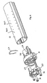
- eine perspektivische Explosionsdarstellung des Kopfstücks einer Heizrohrabdeckung, in das die Zumesseinrichtung aus Figur 5 einsteckbar ist.
- Das in den Figuren gezeigte Haarformgerät ist ein sogenannter Straightener, mit dem gelocktes bzw. gekräuseltes Haar glatt gezogen, aber auch in andere gewünschte Form gebracht werden kann. Es ist als gasbetriebener Dampffrisierstab ausgebildet, bei dem ein Verdampfer mittels eines Gasbrenners erwärmt wird und Dampf erzeugt.
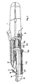
- Wie die Figuren 1 und 2 zeigen, besitzt das Gerät einen im wesentlichen zylindrischen Handteil 1, an dem das Gerät gegriffen werden kann. Stirnseitig an den Handteil 1 ist ein Formstab 2 angesetzt, mit dem die Haare geformt bzw. bearbeitet werden können. Ein Klemmmaul 3 liegt halbschalenförmig auf einer Mantelflächenseite des beheizten Formstabs 2 und kann mittels einer Wipptaste 4 von dem Formstab 2 weggeschwenkt werden.
- Im Inneren des Formstabs 2 ist als Heizvorrichtung zur Beheizung des Formstabs 2 ein Brenner 5 angeordnet, mit dem ein geeignetes Brenngas katalytisch verbrannt werden kann. Der Brenner 5 wird über eine Gaszufuhr 6 aus einer Gaskartusche gespeist, die im Innenraum des Handteils 1 aufgenommen werden kann. Über einen Schalter 7 auf der Außenseite des Handteils 1 kann die Gaszufuhr 6 gesteuert werden. Eine dem Brenner 5 zugeordnete Zündeinrichtung kann mit einem Zündschalter 8, der ebenfalls am Handteil 1 vorgesehen ist, betätigt werden.
- Wie Figur 2 zeigt, ist am stirnseitigen Ende des Brenners 5 ein Verdampfer 9 angeordnet. Eine Verdampferplatte 10 verschließt stirnseitig das Brennrohr 11 des Brenners 5 und trennt den Brennraum von einer Verdampferkammer 12. Die Verdampferkammer 12 wird von einer Brennrohrabdeckung 13, die rohrförmig ausgebildet ist und über dem Brennrohr 11 sitzt, sowie einem die Brennrohrabdeckung 13 stirnseitig verschließenden Kopfstück 14 (vgl. Figur 6) sowie der genannten Verdampferplatte 10 begrenzt.
- An einem stirnseitigen, dem Handteil 1 abgewandten Ende des Geräts ist ein Tank 15 vorgesehen, aus dem der Verdampfer 9 mit Wasser versorgt wird, das im Verdampfer 9 verdampft wird. Der Tank 15 ist derart geformt, dass er die Kontur des restlichen Gerätekorpus im wesentlichen stetig fortsetzt. Wie die Figuren 1, 2 und 4 zeigen, bildet der Tank 15 die Spitze des Formstabs 2 und besitzt einen im wesentlichen halbmondförmigen Querschnitt, dessen Fläche sich zur Spitze hin verkleinert. Mit einer Flachseite das halbmondförmigen Querschnitts, die sich etwa parallel zur Längsachse des Geräts erstreckt, liegt der Tank 15 unter dem freien Ende des Klemmmauls 3, wenn dieses auf den Formstab 2 geschwenkt ist. Das Klemmmaul 3 deckt die genannte Flachseite 16 des Tanks 15 dabei ab.
- Der Tank 15 ist in Längsrichtung des Geräts axial in das Kopfstück 14 der Brennrohrabdekkung 13 eingesteckt und kann axial von dem Gerät abgenommen werden, um den Tank zu befüllen. Ein Tankdeckel 17 ist auf der im montierten Zustand vom Klemmmaul 3 abgedeckten Flachseite 16 des Tanks angeordnet, so dass er lediglich dann zugänglich ist, wenn der Tank 15 vom Rest des Dampffrisierstabs abgenommen ist. Wie Figur 3 zeigt, kann der Tankdeckel 17 erst dann aufgeschwenkt werden, wenn der Tank 15 nach vorne abgeschoben ist. Der Tankdeckel 17 ist vorzugsweise eine Klappe, die im geschlossenen Zustand bündig auf der Flachseite 16 aufliegt und mit einer Dichtung in Form eines Pfropfens 18 die unter dem Tankdeckel 17 liegende Tanköffnung fluiddicht verschließt. Die spezielle Anordnung und Ausbildung des Tankdeckels 17 stellt zweierlei sicher : Zum einen wird das Gerät davor bewahrt, zur Befüllung des Tanks insgesamt unter einen Wasserhahn gehalten zu werden, da der Tankdeckel nur in der demontierten Stellung des Tanks 15 zu öffnen ist. Zum anderen verhindert die Anordnung des Tankdeckels 17 unter einer Abdeckung, die vom Klemmmaul 3 gebildet wird, das sich der Tankdeckel 17 ungewollt im Betrieb öffnet.
- Wie die Figuren 2 und 5 zeigen, ist zwischen dem Tank 15 und dem Verdampfer 9 eine Zumesseinrichtung 19 vorgesehen, die eine dosierte Abgabe von Flüssigkeit aus dem Tank an den. Verdampfer erlaubt. Die Zumesseinrichtung 19 umfasst einen Docht 20 in Form einer zusammengeschlagenen Filzplatte, die passgenau in einer sich axial erstreckenden Dochtführung 21 aufgenommen ist: Wie Figur 5 zeigt, sitzt der Docht -20 in einem Tankboden 22, mit dem der Korpus des Tanks 15 verdampferseitig verschlossen werden kann. Der Tankboden 22 ist als separates Teil ausgebildet und kann in eine entsprechende Ausnehmung im Tank 15 passgenau eingesteckt werden, wobei ein O-Ring 23 als Dichtung zwischen dem Tankboden und dem restlichen Korpus des Tanks 15 fungiert. Wie Figur 2 zeigt, erstreckt sich der Tankboden 22 radial zur Gerätelängsachse, während die an dem Tankboden 22 angeformte Dochtführung 21 sich axial erstreckt. Der Docht 20 ragt in das Innere des Tanks 15 hinein, wobei er zur Flachseite 16 des Tanks hin angeordnet ist und sich etwa koaxial zu dem Brenner 5 erstreckt. Das aus dem Tank herausragende Ende des Dochts 20 besitzt eine V-förmige Auffächerung 24. Die Enden der als Docht fungierenden Filzplatte sind im Bereich der Auffächerung 24 mit Heftklammern 25 an Innenumfangsflächen der Dochtführung 21 fixiert (vgl. Figuren 2 und 5). Über ein Entlüftungsventil 38 im Tankboden 22 ist der Tank entlüftet.
- Mit der vom Tank 15 vorspringenden Dochtführung 21 ist der Tank 15 in das Kopfstück 14 der Brennrohrabdeckung 13 einsteckbar, so dass der Docht 20 in das Innere der Verdampferkammer 12 ragt. Wie Figur 6 zeigt, besitzt das Kopfstück 14 einen zylindrischen Ansatz 26, der eine Innenausnehmung bildet, in der die etwa zylindrische Dochtführung 21 einsteckbar ist. Das Kopfstück 14 sitzt fest auf der Brennrohrabdeckung 13. Der Tank 15 sitzt mit der Dochtführung 21 jedoch axial verschieblich in dem Kopfstück 14. Wie Figur 6 verdeutlicht, ist der Tankboden 22 bzw. dessen Dochtführung 21 über eine Schnappfeder 27 in dem Kopfstück 14 gesichert. Die U-förmige Schnappfeder 27 sitzt in tangentialen Ausnehmungen 28 auf dem Ansatz 26, so dass die Schenkel der Schnappfeder 27 auf die Innenseite der im Ansatz 26 ausgebildeten Ausnehmung vorspringen. Die Schnappfeder 27 ist dabei axial auf dem Ansatz 26 festgelegt, die Schenkel der Schnappfeder 27 können jedoch radial auffedern. Wird der Tank 15 mit der Dochtführung 21 in das Kopfstück 14 eingeschoben, rutschen die Schenkel der Schnappfeder 27 über einen radialen Vorsprung am Außenumfang der Dochtführung 21. Ist die Dochtführung 21 weit genug eingeschoben, schnappt die Schnappfeder 27 wieder zurück und sichert den Tank 15 gegen unbeabsichtigtes Herausziehen aus dem Gerät. Trotz der Rastsicherung ist ein axiales Verschieben des Tanks zum Zwecke der Wasserzufuhr in den Verdampfer möglich.
- Zwischen dem Kopfstück 14 der Brennrohrabdeckung 13 und dem Tank 15 ist eine Vorspanneinrichtung in Form einer Feder 29 vorgesehen. An dem Kopfstück 14 ist eine Stempelplatte 30, über vier Schraubbolzen 31 axial verschieblich geführt, wobei die Verschieblichkeit der Stempelptatte 30 über Anschläge begrenzt ist, die einerseits von den Köpfen der Bolzen 31 und andererseits von der Stirnseite des Kopfstücks 14 gebildet werden. Zwischen der Stempelplatte 13 und dem Kopfstück 14 ist die Feder 29 geschaltet, die die Stempelplatte 30 gemäß Figur 6 nach links gegen die Köpfe der Bolzen 31 drückt.
- Wird der Tank 15 in das Kopfstück 14 eingesteckt, liegt die Stempelplatte 30 am Tank 15 an. Gegen die Stellkraft der Stempelplatte 30 kann der Tank 15 noch weiter in das Kopfstück 14 eingedrückt werden. Die Feder 29 sorgt hingegen für eine Rückstellung.
- Wie Figur 5 zeigt, sitzt auf der Außenmantelfläche der Dochtführung 21 eine Lippendichtung 32, die die Verdampferkammer 12 zum Tank 15 hin abdichtet bzw. den Zwischenraum zwischen der Dochtführung 21 und der Innenausnehmung im Ansatz 26 des Kopfstücks 14 schließt. Dabei stellt die Lippendichtung 32 die Abdichtung auch bei einer entsprechenden Verschiebung des Tanks 15 sicher.
- Um Wasser aus dem Tank 14 in den Verdampfer 9 zu dosieren, muss der Tank 15 gemäß Figur 2 nach rechts verschoben werden, so dass der Tankboden 22 mit seiner Dochtführung 21 entgegen der Beaufschlagung durch die Stempelplatte 30 tiefer in die Verdampferkammer 12 eindringt. Dabei gerät die V-förmige Auffächerung 24 des Dochts 20 auf die ebenfalls V-förmige Oberfläche der Verdampferplatte 10. Die durch den Docht 20 durch dessen Kapillarwirkung zur Auffächerung 24 geförderte Flüssigkeitsmenge verdampft sodann auf der Verdampferplatte 10. Über Dampfaustrittsöffnungen 33 in der Brennrohrabdeckung 13 kann der Dampf sodann auf die um den Formstab 2 gewickelten Haare gegeben werden. Wie aus den Figuren 1, 2 und 4 hervorgeht, kann der Tank 15 dabei nicht nur an seiner Stirnseite gedrückt werden, um die gewünschte Verschiebung zu erzielen. An dem Tank 15 ist ein halbschalenförmiges Verbindungsstück 33 angeformt, das sich bis zum formstabseitigen Ende des Handteils 1 erstreckt. Dort ist an das Verbindungsstück 33 eine Betätigungstaste 34 mit einer rutschhemmenden Oberfläche in Form einer Querriffelung 35 angeformt. Die Betätigungstaste 34 liegt auf der der Wipptaste 4 gegenüberliegenden Seite des Handteils 1 und erlaubt es, den Tank 15 auch mit der das Handteil 1 greifenden Hand zu betätigen, d. h. in axialer Richtung zu verschieben, um Dosierflüssigkeit in den Verdampfer 9 zu transportieren. Wie Figur 4 zeigt, bildet die Betätigungstaste 34 eine wulstförmige Erhebung am Ende des Verbindungsstücks 33, das sich im wesentlichen parallel zur Längsrichtung des Geräts um den Formstab 2 herum erstreckt. Das Verbindungsstück 33 besitzt mehrere Längsrippen 35 und ist als Wärmeschutzabdeckung ausgebildet. Wie Figur 3 zeigt, umgreift das Verbindungsstück 33 den Gehäusekorpus des Geräts im Bereich des Formstabs 2 dabei so weit, dass eine Längsführung des Verbindungsstücks 33 bewirkt wird. Es kann eine schwalbenschwänzartige Längsführung 36 zwischen dem Verbindungsstück 33 und dem Gerätegehäuse vorgesehen sein. Vorzugsweise stützten Längsrippen 37 das Verbindungsstück 33 über dessen gesamten Querschnitt ab. Hierdurch wird eine vorteilhafte Bedienbarkeit der Betätigungstaste 34 erreicht. Ein Verklemmen des Verbindungsstücks 33 ist verhindert.
Claims (16)
- Haarformgerät mit einem Handteil (1), einem mit dem Handteil (1) verbundenen Formstab (2), einem Verdampfer (9), einem Tank (15), aus dem der Verdampfer (9) mit Verdampfungsflüssigkeit versorgbar ist, sowie einer Zumesseinrichtung (19), mit der die in den Verdampfer (9) gelangende Verdampfungsflüssigkeitsmenge steuerbar ist, wobei der Tank (15) beweglich gelagert, die Zumesseinrichtung (19) durch Bewegung des Tanks (15) betätigbar und die Zumesseinrichtung (19) mit einer am Handteil (1) vorgesehenen Betätigungstaste (34) verbunden ist, dadurch gekennzeichnet, dass der Tank (15) am dem Handteil (1) gegenüber liegenden Endabschnitt des Formstabes (2) angeordnet und mit der Betätigungstaste (34) über ein Verbindungsstück (33) verbunden ist.
- Haarformgerät nach Anspruch 1, dadurch gekennzeichnet, dass das Verbindungsstück sich halbschalenförmig um den bzw. entlang dem Formstab (2) erstreckt und/oder eine Wärmeschutzabdeckung bildet.
- Haarformgerät nach einem der vorhergehenden Ansprüche, wobei das Verbindungsstück (33) an dem Formstab (2) längsgeführt und/oder in Längsrichtung verschieblich abgestützt ist, vorzugsweise auf Längsrippen an dem Formstab (2) aufliegt.
- Haarformgerät nach einem der vorhergehenden Ansprüche, wobei der Tank (15) und die Betätigungstaste (34) miteinander einstückig ausgebildet sind.
- Haarformgerät nach einem der vorhergehenden Ansprüche; wobei die Betätigungstaste (34) auf einer einem schwenkbaren Klemmmaul (3), das mit dem Formstab (2) zusammenwirkt, gegenüberliegenden Geräteseite angeordnet ist.
- Haarformgerät nach einem der vorhergehenden Ansprüche, wobei die Zumesseinrichtung (19) einen Docht (20) aufweist, der durch eine dem Verdampfer (9) gegenüberliegende Tankwandung (22) hindurchtritt und durch Bewegen des Tanks zu einer Verdampferfläche (10) hin und von dieser weg bewegbar ist.
- Haarformgerät nach dem vorhergehenden Anspruch; wobei der Docht (20) an seinem der Verdampferfläche (10) zugewandten Ende eine vorzugsweise V-förmige Auffächerung (24) und die Verdampferfläche (10) eine hierzu komplementäre Kontur aufweist.
- Haarformgerät nach einem der vorhergehenden Ansprüche, wobei der Docht (20) außermittig in den Tank hineinragt.
- Haarformgerät nach einem der vorhergehenden Ansprüche, wobei die eine Tankwandung (22) eine vorzugsweise integral angeformte Dochtführung (21) aufweist, die axial in eine Verdampferkammerwandung (14) einsteckbar ist, wobei zwischen der Dochtführung (21) und der Verdampferkammerwandung (14) eine Radialdichtung (32) vorgesehen ist und/oder zwischen der Dochtführung (21) und der Verdampferkammerwandung (14) eine Rastsicherung (27), insbesondere eine Sicherungsfeder, vorgesehen ist.
- Haarformgerät nach einem der vorhergehenden Ansprüche, wobei der Tank (15) in Gerätelängsrichtung axial verschiebbar gelagert ist, insbesondere relativ zu dem Verdampfer (9) axial verschieblich geführt und/oder elastisch vorgespannt ist.
- Haarformgerät nach einem der vorhergehenden Ansprüche, wobei der Tank (15) über ein Entlüftungsventil (38) entlüftet ist, wobei vorzugsweise das Entlüftungsventil (38) in dem den Docht (20) aufnehmenden Tankboden (22) angeordnet ist.
- Haarformgerät nach einem der vorhergehenden Ansprüche, wobei der Tank (15) einen Deckel (17) aufweist, der im montierten Zustand des Tanks von einem Geräteabschnitt (3) abgedeckt ist und nur im demontierten Zustand des Tanks zugänglich und/oder zu öffnen ist.
- Haarformgerät nach dem vorhergehenden Anspruch, wobei der Deckel (17) an einem stirnseitigen, dem Handteil (1) abgewandten Endabschnitt des Tanks (15) angeordnet ist.
- Haarformgerät nach einem der vorhergehenden Ansprüche, wobei ein Tankdekkelabschnitt des Tanks (15) unter dem mit dem Formstab (2) zusammenwirkenden Klemmmaul (3) angeordnet ist.
- Haarformgerät nach einem der vorhergehenden Ansprüche, wobei der Tank (15) in das Kopfstück (14) einer Heizrohrabdeckung (13) einsteckbar ist, die den Verdampfer (9) umgibt und/oder eine Verdampferkammer (12) begrenzt.
- Haarformgerät nach einem der vorhergehenden Ansprüche, wobei der Tank (15) sich im wesentlichen in einem Gerätesektor auf einer Hälfte des Geräts erstreckt, vorzugsweise auf einer dem Klemmmaul (3) des Geräts gegenüberliegenden-Geräteseite angeordnet ist und/oder einen in etwa halbmondförmigen Querschnitt mit einer Flachseite (16), an der der Tankdeckel (17) vorgesehen ist, aufweist.
Applications Claiming Priority (3)
| Application Number | Priority Date | Filing Date | Title |
|---|---|---|---|
| DE10239713A DE10239713A1 (de) | 2002-08-29 | 2002-08-29 | Haarformgerät |
| DE10239713 | 2002-08-29 | ||
| PCT/EP2003/007977 WO2004019723A1 (de) | 2002-08-29 | 2003-07-22 | Haarformgerät |
Publications (2)
| Publication Number | Publication Date |
|---|---|
| EP1531697A1 EP1531697A1 (de) | 2005-05-25 |
| EP1531697B1 true EP1531697B1 (de) | 2007-08-22 |
Family
ID=31724156
Family Applications (1)
| Application Number | Title | Priority Date | Filing Date |
|---|---|---|---|
| EP03790807A Expired - Lifetime EP1531697B1 (de) | 2002-08-29 | 2003-07-22 | Haarformgerät |
Country Status (6)
| Country | Link |
|---|---|
| US (1) | US7325551B2 (de) |
| EP (1) | EP1531697B1 (de) |
| AT (1) | ATE370676T1 (de) |
| CA (1) | CA2463848A1 (de) |
| DE (2) | DE10239713A1 (de) |
| WO (1) | WO2004019723A1 (de) |
Families Citing this family (27)
| Publication number | Priority date | Publication date | Assignee | Title |
|---|---|---|---|---|
| DE10239713A1 (de) | 2002-08-29 | 2004-03-18 | Braun Gmbh | Haarformgerät |
| USD534308S1 (en) * | 2004-11-18 | 2006-12-26 | Braun Gmbh | Hairstyler |
| USD541472S1 (en) * | 2005-06-01 | 2007-04-24 | Mcbride Research Laboratory, Inc. | Hair iron |
| DE102005027980A1 (de) * | 2005-06-16 | 2006-12-28 | Braun Gmbh | Haarformgerät |
| DE202006013468U1 (de) * | 2006-09-01 | 2008-01-10 | Wik Far East Ltd. | Haarformgerät |
| FR2921804B1 (fr) * | 2007-10-03 | 2011-05-06 | Seb Sa | Appareil portatif de traitement des cheveux a la vapeur |
| EP2364609B1 (de) | 2010-03-12 | 2016-04-27 | Braun GmbH | Haarstylingvorrichtung |
| DE202010003565U1 (de) | 2010-03-12 | 2010-07-22 | Braun Gmbh | Haarformgerät |
| FR2967017B1 (fr) * | 2010-11-05 | 2014-04-04 | Seb Sa | Appareil de coiffure a vapeur |
| US20130192625A1 (en) * | 2012-02-01 | 2013-08-01 | Jmastm, Llc | Applying hair treatment with a hair iron |
| US8757175B1 (en) | 2012-12-13 | 2014-06-24 | Conair Corporation | Hair styling apparatus |
| US9072355B1 (en) | 2013-05-30 | 2015-07-07 | Nicole Irene Magnani | Sharable hair accessory |
| USD716496S1 (en) | 2013-10-28 | 2014-10-28 | Conair Corporation | Hair straightener apparatus |
| KR101391803B1 (ko) * | 2013-10-28 | 2014-05-07 | 박창수 | 나선형 헤어스타일 작업이 용이한 회전형 모발성형장치 |
| FI3922128T3 (fi) | 2015-04-03 | 2023-04-12 | Siirrettävä lämmitysjärjestelmä | |
| USD765910S1 (en) | 2015-05-08 | 2016-09-06 | Schawbel Technologies Llc | Portable curling iron |
| USD758013S1 (en) * | 2015-05-08 | 2016-05-31 | Schawbel Technologies Llc | Hair straightener |
| USD776798S1 (en) | 2015-05-08 | 2017-01-17 | Schawbel Technologies Llc | Adaptor for a fuel cartridge |
| USD796113S1 (en) | 2015-05-08 | 2017-08-29 | Schawbel Technologies Llc | Fuel cartridge |
| USD776346S1 (en) | 2015-06-01 | 2017-01-10 | Nicole Irene Magnani | Multi-part joinable clip |
| USD794813S1 (en) | 2015-07-15 | 2017-08-15 | Schawbel Technologies Llc | Heat pack |
| GB201605100D0 (en) * | 2016-03-24 | 2016-05-11 | Nicoventures Holdings Ltd | Vapour provision system |
| GB201605101D0 (en) | 2016-03-24 | 2016-05-11 | Nicoventures Holdings Ltd | Electronic vapour provision system |
| GB201605105D0 (en) | 2016-03-24 | 2016-05-11 | Nicoventures Holdings Ltd | Vapour provision apparatus |
| FR3053576B1 (fr) * | 2016-07-06 | 2018-07-13 | Seb S.A. | Appareil de coiffure a vapeur pourvu d'un reservoir de fluide mobile |
| FR3053577B1 (fr) * | 2016-07-06 | 2018-07-13 | Seb S.A. | Appareil de coiffure a vapeur |
| US20200015562A1 (en) * | 2018-03-19 | 2020-01-16 | Charlotte Levingston-Johnson | Cordless hair styling apparatus and method of use |
Family Cites Families (9)
| Publication number | Priority date | Publication date | Assignee | Title |
|---|---|---|---|---|
| US3835292A (en) * | 1973-02-28 | 1974-09-10 | Clairol Inc | Steam curling iron |
| US3921648A (en) * | 1975-01-02 | 1975-11-25 | George Barradas | Hair curling implement |
| US3937232A (en) * | 1975-01-29 | 1976-02-10 | Continental Hair Products, Inc. | Liquid feeding means for steam-producing appliance |
| US4209685A (en) * | 1975-04-28 | 1980-06-24 | Clairol Incorporated | Hair straightening or waving mandrel for use with a vapor generating curling iron |
| AU6048194A (en) * | 1993-11-19 | 1995-06-06 | Gary Maznik | Steam hair styling apparatus |
| JPH10272010A (ja) * | 1997-03-31 | 1998-10-13 | Matsushita Electric Works Ltd | ヘアーアイロン |
| DE29822238U1 (de) * | 1998-12-14 | 2000-04-20 | Wik Elektro-Hausgeräte-Vertriebsgesellschaft mbH & Co Produktions-KG, 45355 Essen | Dampfaufsatz für einen Frisierstab |
| DE10012193A1 (de) * | 2000-03-13 | 2001-09-27 | Braun Gmbh | Haarformgerät, insbesondere Dampffrisierstab |
| DE10239713A1 (de) | 2002-08-29 | 2004-03-18 | Braun Gmbh | Haarformgerät |
-
2002
- 2002-08-29 DE DE10239713A patent/DE10239713A1/de not_active Withdrawn
-
2003
- 2003-07-22 EP EP03790807A patent/EP1531697B1/de not_active Expired - Lifetime
- 2003-07-22 CA CA002463848A patent/CA2463848A1/en not_active Abandoned
- 2003-07-22 DE DE50308016T patent/DE50308016D1/de not_active Expired - Lifetime
- 2003-07-22 WO PCT/EP2003/007977 patent/WO2004019723A1/de not_active Ceased
- 2003-07-22 AT AT03790807T patent/ATE370676T1/de not_active IP Right Cessation
-
2004
- 2004-04-28 US US10/834,598 patent/US7325551B2/en not_active Expired - Fee Related
Also Published As
| Publication number | Publication date |
|---|---|
| WO2004019723A1 (de) | 2004-03-11 |
| DE50308016D1 (de) | 2007-10-04 |
| US7325551B2 (en) | 2008-02-05 |
| EP1531697A1 (de) | 2005-05-25 |
| US20040244810A1 (en) | 2004-12-09 |
| CA2463848A1 (en) | 2004-03-11 |
| ATE370676T1 (de) | 2007-09-15 |
| DE10239713A1 (de) | 2004-03-18 |
Similar Documents
| Publication | Publication Date | Title |
|---|---|---|
| EP1531697A1 (de) | Haarformger t | |
| EP1170061B1 (de) | Austragvorrichtung für Medien | |
| EP0688543B1 (de) | Zahnreinigungseinrichtung mit einem Handstück | |
| DE1457440C3 (de) | Vorrichtung zum Abgeben eines Gemisches aus zwei treibmittelbeaufschlagten flüssigen Komponenten | |
| EP1652589A2 (de) | Vorrichtung zum Mischen von zwei unterschiedlichen Komponenten | |
| DE102008038654B4 (de) | Abgabekopf mit schwenkbarem Ventilelement | |
| EP2134475A1 (de) | Vorrichtung zum aufsprühen von pigmentierten flüssigkeiten | |
| DE19610456A1 (de) | Austragvorrichtung für Medien | |
| DE102010035891A1 (de) | Spritze für den Gebrauch mit einer Dosiervorrichtung | |
| EP2801335B1 (de) | Spritze | |
| WO1998026823A1 (de) | Handbetätigbares gerät zur ausgabe insbesondere medizinischer substanzen | |
| EP1267660B1 (de) | Haarformgerät, insbesondere dampffrisierstab | |
| EP3538276B1 (de) | Handdosiervorrichtung und handdosiervorrichtungsanordnung | |
| WO2010049090A1 (de) | Aufträgervorrichtung | |
| EP1272067B1 (de) | Haarformgerät, insbesondere dampffrisierstab | |
| DE69623793T2 (de) | Handgriff mit betätiger und durch diesen handgriff betätigter apparat | |
| EP1466671B1 (de) | Spender | |
| DE4106386A1 (de) | Geraet zum auftragen von fluessigkeit | |
| DE2166148C3 (de) | Aerosolzerstäuber | |
| DE2634972A1 (de) | Fluessigkeits-zumesseinrichtung fuer dampflockenstaebe o.dgl. | |
| EP3575102B1 (de) | Auftraggerät | |
| DE3644960C2 (de) | Ger{t mit einem eine viskose Fl}ssigkeit enthaltenden Beh{lter | |
| DE3523538C1 (de) | Spritzpistole | |
| EP0765720A2 (de) | Pistole für Polyurethanschaum oder dgl. | |
| DE2631738B2 (de) | Vorrichtung zur dosierten Flüssigkeitsausgabe in einem Haarbehandlungsgerät |
Legal Events
| Date | Code | Title | Description |
|---|---|---|---|
| PUAI | Public reference made under article 153(3) epc to a published international application that has entered the european phase |
Free format text: ORIGINAL CODE: 0009012 |
|
| 17P | Request for examination filed |
Effective date: 20040403 |
|
| AK | Designated contracting states |
Kind code of ref document: A1 Designated state(s): AT BE BG CH CY CZ DE DK EE ES FI FR GB GR HU IE IT LI LU MC NL PT RO SE SI SK TR |
|
| GRAP | Despatch of communication of intention to grant a patent |
Free format text: ORIGINAL CODE: EPIDOSNIGR1 |
|
| GRAS | Grant fee paid |
Free format text: ORIGINAL CODE: EPIDOSNIGR3 |
|
| GRAA | (expected) grant |
Free format text: ORIGINAL CODE: 0009210 |
|
| AK | Designated contracting states |
Kind code of ref document: B1 Designated state(s): AT BE BG CH CY CZ DE DK EE ES FI FR GB GR HU IE IT LI LU MC NL PT RO SE SI SK TR |
|
| REG | Reference to a national code |
Ref country code: GB Ref legal event code: FG4D Free format text: NOT ENGLISH |
|
| REG | Reference to a national code |
Ref country code: CH Ref legal event code: EP |
|
| REG | Reference to a national code |
Ref country code: IE Ref legal event code: FG4D Free format text: LANGUAGE OF EP DOCUMENT: GERMAN |
|
| REF | Corresponds to: |
Ref document number: 50308016 Country of ref document: DE Date of ref document: 20071004 Kind code of ref document: P |
|
| PG25 | Lapsed in a contracting state [announced via postgrant information from national office to epo] |
Ref country code: BG Free format text: LAPSE BECAUSE OF FAILURE TO SUBMIT A TRANSLATION OF THE DESCRIPTION OR TO PAY THE FEE WITHIN THE PRESCRIBED TIME-LIMIT Effective date: 20071122 Ref country code: NL Free format text: LAPSE BECAUSE OF FAILURE TO SUBMIT A TRANSLATION OF THE DESCRIPTION OR TO PAY THE FEE WITHIN THE PRESCRIBED TIME-LIMIT Effective date: 20070822 Ref country code: ES Free format text: LAPSE BECAUSE OF FAILURE TO SUBMIT A TRANSLATION OF THE DESCRIPTION OR TO PAY THE FEE WITHIN THE PRESCRIBED TIME-LIMIT Effective date: 20071203 Ref country code: FI Free format text: LAPSE BECAUSE OF FAILURE TO SUBMIT A TRANSLATION OF THE DESCRIPTION OR TO PAY THE FEE WITHIN THE PRESCRIBED TIME-LIMIT Effective date: 20070822 |
|
| NLV1 | Nl: lapsed or annulled due to failure to fulfill the requirements of art. 29p and 29m of the patents act | ||
| GBV | Gb: ep patent (uk) treated as always having been void in accordance with gb section 77(7)/1977 [no translation filed] |
Effective date: 20070822 |
|
| REG | Reference to a national code |
Ref country code: IE Ref legal event code: FD4D |
|
| EN | Fr: translation not filed | ||
| PG25 | Lapsed in a contracting state [announced via postgrant information from national office to epo] |
Ref country code: DK Free format text: LAPSE BECAUSE OF FAILURE TO SUBMIT A TRANSLATION OF THE DESCRIPTION OR TO PAY THE FEE WITHIN THE PRESCRIBED TIME-LIMIT Effective date: 20070822 Ref country code: GR Free format text: LAPSE BECAUSE OF FAILURE TO SUBMIT A TRANSLATION OF THE DESCRIPTION OR TO PAY THE FEE WITHIN THE PRESCRIBED TIME-LIMIT Effective date: 20071123 |
|
| PG25 | Lapsed in a contracting state [announced via postgrant information from national office to epo] |
Ref country code: GB Free format text: LAPSE BECAUSE OF FAILURE TO SUBMIT A TRANSLATION OF THE DESCRIPTION OR TO PAY THE FEE WITHIN THE PRESCRIBED TIME-LIMIT Effective date: 20070822 Ref country code: SK Free format text: LAPSE BECAUSE OF FAILURE TO SUBMIT A TRANSLATION OF THE DESCRIPTION OR TO PAY THE FEE WITHIN THE PRESCRIBED TIME-LIMIT Effective date: 20070822 Ref country code: PT Free format text: LAPSE BECAUSE OF FAILURE TO SUBMIT A TRANSLATION OF THE DESCRIPTION OR TO PAY THE FEE WITHIN THE PRESCRIBED TIME-LIMIT Effective date: 20080122 Ref country code: CZ Free format text: LAPSE BECAUSE OF FAILURE TO SUBMIT A TRANSLATION OF THE DESCRIPTION OR TO PAY THE FEE WITHIN THE PRESCRIBED TIME-LIMIT Effective date: 20070822 Ref country code: IE Free format text: LAPSE BECAUSE OF FAILURE TO SUBMIT A TRANSLATION OF THE DESCRIPTION OR TO PAY THE FEE WITHIN THE PRESCRIBED TIME-LIMIT Effective date: 20070822 |
|
| PLBE | No opposition filed within time limit |
Free format text: ORIGINAL CODE: 0009261 |
|
| STAA | Information on the status of an ep patent application or granted ep patent |
Free format text: STATUS: NO OPPOSITION FILED WITHIN TIME LIMIT |
|
| PG25 | Lapsed in a contracting state [announced via postgrant information from national office to epo] |
Ref country code: SE Free format text: LAPSE BECAUSE OF FAILURE TO SUBMIT A TRANSLATION OF THE DESCRIPTION OR TO PAY THE FEE WITHIN THE PRESCRIBED TIME-LIMIT Effective date: 20071122 Ref country code: RO Free format text: LAPSE BECAUSE OF FAILURE TO SUBMIT A TRANSLATION OF THE DESCRIPTION OR TO PAY THE FEE WITHIN THE PRESCRIBED TIME-LIMIT Effective date: 20070822 |
|
| 26N | No opposition filed |
Effective date: 20080526 |
|
| REG | Reference to a national code |
Ref country code: CH Ref legal event code: PL |
|
| PG25 | Lapsed in a contracting state [announced via postgrant information from national office to epo] |
Ref country code: MC Free format text: LAPSE BECAUSE OF NON-PAYMENT OF DUE FEES Effective date: 20080731 |
|
| PG25 | Lapsed in a contracting state [announced via postgrant information from national office to epo] |
Ref country code: EE Free format text: LAPSE BECAUSE OF FAILURE TO SUBMIT A TRANSLATION OF THE DESCRIPTION OR TO PAY THE FEE WITHIN THE PRESCRIBED TIME-LIMIT Effective date: 20070822 |
|
| PG25 | Lapsed in a contracting state [announced via postgrant information from national office to epo] |
Ref country code: SI Free format text: LAPSE BECAUSE OF FAILURE TO SUBMIT A TRANSLATION OF THE DESCRIPTION OR TO PAY THE FEE WITHIN THE PRESCRIBED TIME-LIMIT Effective date: 20070822 Ref country code: LI Free format text: LAPSE BECAUSE OF NON-PAYMENT OF DUE FEES Effective date: 20080731 Ref country code: CH Free format text: LAPSE BECAUSE OF NON-PAYMENT OF DUE FEES Effective date: 20080731 |
|
| PG25 | Lapsed in a contracting state [announced via postgrant information from national office to epo] |
Ref country code: CY Free format text: LAPSE BECAUSE OF FAILURE TO SUBMIT A TRANSLATION OF THE DESCRIPTION OR TO PAY THE FEE WITHIN THE PRESCRIBED TIME-LIMIT Effective date: 20070822 |
|
| PG25 | Lapsed in a contracting state [announced via postgrant information from national office to epo] |
Ref country code: AT Free format text: LAPSE BECAUSE OF NON-PAYMENT OF DUE FEES Effective date: 20080722 |
|
| PG25 | Lapsed in a contracting state [announced via postgrant information from national office to epo] |
Ref country code: HU Free format text: LAPSE BECAUSE OF FAILURE TO SUBMIT A TRANSLATION OF THE DESCRIPTION OR TO PAY THE FEE WITHIN THE PRESCRIBED TIME-LIMIT Effective date: 20080223 Ref country code: BE Free format text: LAPSE BECAUSE OF NON-PAYMENT OF DUE FEES Effective date: 20080731 Ref country code: LU Free format text: LAPSE BECAUSE OF NON-PAYMENT OF DUE FEES Effective date: 20080722 |
|
| PG25 | Lapsed in a contracting state [announced via postgrant information from national office to epo] |
Ref country code: TR Free format text: LAPSE BECAUSE OF FAILURE TO SUBMIT A TRANSLATION OF THE DESCRIPTION OR TO PAY THE FEE WITHIN THE PRESCRIBED TIME-LIMIT Effective date: 20070822 |
|
| PG25 | Lapsed in a contracting state [announced via postgrant information from national office to epo] |
Ref country code: IT Free format text: LAPSE BECAUSE OF NON-PAYMENT OF DUE FEES Effective date: 20080731 |
|
| PG25 | Lapsed in a contracting state [announced via postgrant information from national office to epo] |
Ref country code: FR Free format text: LAPSE BECAUSE OF FAILURE TO SUBMIT A TRANSLATION OF THE DESCRIPTION OR TO PAY THE FEE WITHIN THE PRESCRIBED TIME-LIMIT Effective date: 20080418 |
|
| PGFP | Annual fee paid to national office [announced via postgrant information from national office to epo] |
Ref country code: DE Payment date: 20120731 Year of fee payment: 10 |
|
| REG | Reference to a national code |
Ref country code: DE Ref legal event code: R119 Ref document number: 50308016 Country of ref document: DE Effective date: 20140201 |
|
| PG25 | Lapsed in a contracting state [announced via postgrant information from national office to epo] |
Ref country code: DE Free format text: LAPSE BECAUSE OF NON-PAYMENT OF DUE FEES Effective date: 20140201 |