EP1531306B1 - Plaque en plastique pour le montage de tubes dans lesquels circule un fluide - Google Patents
Plaque en plastique pour le montage de tubes dans lesquels circule un fluide Download PDFInfo
- Publication number
- EP1531306B1 EP1531306B1 EP03025900A EP03025900A EP1531306B1 EP 1531306 B1 EP1531306 B1 EP 1531306B1 EP 03025900 A EP03025900 A EP 03025900A EP 03025900 A EP03025900 A EP 03025900A EP 1531306 B1 EP1531306 B1 EP 1531306B1
- Authority
- EP
- European Patent Office
- Prior art keywords
- plate
- pipe holding
- openings
- plate according
- holding plate
- Prior art date
- Legal status (The legal status is an assumption and is not a legal conclusion. Google has not performed a legal analysis and makes no representation as to the accuracy of the status listed.)
- Expired - Lifetime
Links
- 239000004033 plastic Substances 0.000 title claims abstract description 8
- 229920003023 plastic Polymers 0.000 title claims abstract description 8
- 239000012530 fluid Substances 0.000 title claims abstract description 4
- 206010022000 influenza Diseases 0.000 title 1
- 238000010438 heat treatment Methods 0.000 claims abstract description 11
- 229920000139 polyethylene terephthalate Polymers 0.000 claims description 6
- 239000005020 polyethylene terephthalate Substances 0.000 claims description 6
- 229920000728 polyester Polymers 0.000 claims description 3
- -1 polyethylene terephthalate Polymers 0.000 claims description 3
- 238000009413 insulation Methods 0.000 description 8
- 150000001875 compounds Chemical class 0.000 description 7
- 125000006850 spacer group Chemical group 0.000 description 5
- 239000000758 substrate Substances 0.000 description 4
- 238000004382 potting Methods 0.000 description 3
- 238000001816 cooling Methods 0.000 description 2
- 238000009434 installation Methods 0.000 description 2
- 210000000988 bone and bone Anatomy 0.000 description 1
- 239000002826 coolant Substances 0.000 description 1
- 239000011810 insulating material Substances 0.000 description 1
- 230000014759 maintenance of location Effects 0.000 description 1
- 239000002184 metal Substances 0.000 description 1
- 239000011505 plaster Substances 0.000 description 1
- 239000002985 plastic film Substances 0.000 description 1
- 229920006255 plastic film Polymers 0.000 description 1
- 238000011084 recovery Methods 0.000 description 1
- 239000007787 solid Substances 0.000 description 1
- 229920001169 thermoplastic Polymers 0.000 description 1
- 239000004416 thermosoftening plastic Substances 0.000 description 1
- XLYOFNOQVPJJNP-UHFFFAOYSA-N water Substances O XLYOFNOQVPJJNP-UHFFFAOYSA-N 0.000 description 1
Images

Classifications
-
- F—MECHANICAL ENGINEERING; LIGHTING; HEATING; WEAPONS; BLASTING
- F24—HEATING; RANGES; VENTILATING
- F24D—DOMESTIC- OR SPACE-HEATING SYSTEMS, e.g. CENTRAL HEATING SYSTEMS; DOMESTIC HOT-WATER SUPPLY SYSTEMS; ELEMENTS OR COMPONENTS THEREFOR
- F24D3/00—Hot-water central heating systems
- F24D3/12—Tube and panel arrangements for ceiling, wall, or underfloor heating
- F24D3/14—Tube and panel arrangements for ceiling, wall, or underfloor heating incorporated in a ceiling, wall or floor
- F24D3/141—Tube mountings specially adapted therefor
- F24D3/142—Tube mountings specially adapted therefor integrated in prefab construction elements
-
- Y—GENERAL TAGGING OF NEW TECHNOLOGICAL DEVELOPMENTS; GENERAL TAGGING OF CROSS-SECTIONAL TECHNOLOGIES SPANNING OVER SEVERAL SECTIONS OF THE IPC; TECHNICAL SUBJECTS COVERED BY FORMER USPC CROSS-REFERENCE ART COLLECTIONS [XRACs] AND DIGESTS
- Y02—TECHNOLOGIES OR APPLICATIONS FOR MITIGATION OR ADAPTATION AGAINST CLIMATE CHANGE
- Y02B—CLIMATE CHANGE MITIGATION TECHNOLOGIES RELATED TO BUILDINGS, e.g. HOUSING, HOUSE APPLIANCES OR RELATED END-USER APPLICATIONS
- Y02B30/00—Energy efficient heating, ventilation or air conditioning [HVAC]
Definitions
- the invention relates to a pipe receiving plate made of plastic for receiving fluid-flowed pipes, in particular of heating pipes, wherein the plate has molded tube receiving elements.
- the invention further relates to an aggregate of a tube receiving plate and a fastener.
- the pipe receiving plate according to the invention is particularly intended for receiving or laying of heating pipes for underfloor heating. In the pipe receiving plate but also pipes of a cooling system can be laid, for example.
- a pipe receiving plate made of plastic for heating pipes is usually laid on an insulating layer or on an insulating board for thermal and / or impact sound insulation.
- the tube receiving elements are formed as knobs, these knobs are set up for a clamping holder of the heating pipes.
- the nubs are formed as wells, which are down - that is to the insulation board - open and thus form cavities on the insulation board.
- a tube receiving plate of the type mentioned, from which the invention proceeds, is made US 6,539,681 B1 known.
- This tube receiving plate is provided as a spacer plate for a cavity floor. It is intended to rest on a subfloor and has spacer elements and mounting elements for holding pipes for a heating or cooling medium.
- the spacer plate can in particular be produced from a plastic film or from a metal sheet by deep drawing.
- the plate has bumps, which are formed in the shape of a truncated cone and form the spacer elements. In addition, grooves are provided in the plate on the same side as the bumps, which serve to hold the tubes.
- This known tube receiving plate also has the disadvantages described above.
- a pipe receiving plate which belongs to a device for heat insulation and simultaneous heat energy recovery in a building.
- This tube receiving plate is mounted on a layer of heat-insulating material and has on its upper side knobs for receiving pipes. Through the tubes is a medium that can store heat, especially water.
- This known tube receiving plate also has the disadvantages described above.
- the invention is based on the technical problem of providing a tube receiving plate of the type mentioned, in which the disadvantages described above can be avoided and can be installed reliably and precisely in a simple manner and fix.
- the invention teaches a tube receiving plate of the type described above, which is characterized in that it is at least partially transparent.
- Transparent means in the context of the invention, in particular, that a person with average vision with the naked eye through the inventive tube receiving plate can see through and can detect the substrate under the plate or the background behind the plate. It is within the scope of the invention that at least 50%, preferably at least 75% and very preferably at least 90% of the surface of the tube receiving plate is transparent. According to a particularly preferred embodiment of the invention, the entire tube receiving plate or the entire surface of the tube receiving plate is transparent.
- the tube receiving plate according to the invention is suitable for laying the fluid-flowed tubes on the floor or floor or on a wall or on a ceiling of a room.
- the pipe receiving plate is usually laid on a solid surface, for example on screed, concrete or on a wooden floor. But it is also possible to lay the pipe receiving plate on an insulating layer or insulation board for heat and / or impact sound insulation. It is understood that the molded tube receiving elements made of the same plastic as the rest of the plate.
- the tube receiving elements are arranged for a clamping support of the tubes.
- the tube receiving elements are formed as knobs and between the knobs channels for receiving the tubes are provided.
- the knobs are formed hollow inside, that is, the knobs are formed as wells, which are open at the bottom and form cavities on the underlying surface of the plate.
- a very preferred embodiment which is of very particular importance in the context of the invention, is characterized in that a plurality of apertures passing through the plate is provided.
- openings are arranged, which allow access to the underlying surface of the plate, for example, to an insulating layer.
- the openings have for example a circular cross-section.
- nub surfaces here means the side walls and the top of the nubs. Conveniently, only one opening is provided in each knob.
- An embodiment of the invention is characterized in that at least a part of the openings is arranged centrally in the knob tops. It is within the scope of the invention that the openings, which are provided in the nub surfaces of the plate, are arranged only centrally in the center of the knob tops. Preferably, only one opening is centrally present in each case in a knob top.
- This embodiment of the plate according to the invention are particularly suitable for laying the plate on a floor or floor or on a ceiling of a room. The centrally located in the knob tops ensure openings that a final applied to the plate mass (leveling compound or filling or potting compound, screed, plaster, etc.) can be evenly distributed below the knobs or in the cavity of the knobs.
- At least a part of the openings provided in the dimple tops is arranged eccentrically with respect to the upper side center.
- all openings provided in the dimple tops are oriented eccentrically with respect to the topsides centers. The openings are thus arranged as it were offset from the top center away to the side walls.
- an eccentrically arranged opening in the knob top is provided in the openings provided with knobs.
- the aforementioned tube receiving plate is particularly suitable for laying the fluid flowed through pipes on walls.
- the eccentrically arranged openings of a plate are all aligned eccentrically in the same direction. The plate can then be aligned with the wall so that all openings are oriented as it were up to the ceiling. Then the knobs with these openings, so to speak pockets, which can be completely filled in a simple manner with a subsequently applied mass.
- the plate according to the invention consists of a thermoplastic polyester. It is within the scope of the invention that the plate consists of polyethylene terephthalate (PETP).
- PETP polyethylene terephthalate
- the invention further relates to an assembly of a tube receiving plate and a fastener, wherein the fastener is equipped with two attachment holes each having a mounting end, wherein a mounting end is inserted between the studs of the plate, so that the respective attachment opening of this attachment end on a plate passing through the opening is arranged. It is within the scope of the invention that the second attachment end between the nubs of a is inserted adjacent plate and that also here the attachment opening of this attachment end is disposed over an opening passing through the adjacent plate.
- a fixing element such as a nail, an anchor or the like can then be introduced into the ground and in this way the plates are reliably attached to the ground and connected to each other.
- the invention is based on the finding that a very simple and above all functionally reliable and precise installation is possible with the tube receiving plate according to the invention. Due to the transparency of the plate, the ideal substrate, for example a wooden battens, can easily be found for fixing the plate. This is especially relevant when laying the panels in the ceiling or wall area. Due to the transparency of the tube receiving plate according to the invention can be readily recognized whether the intended under the plate insulation layer is laid over the entire surface or completely. Corresponding errors during installation no longer occur. Of particular importance within the scope of the invention are the openings which pass through a tube receiving plate according to the invention. As already stated above, a subsequently applied mass (leveling compound or filling compound or potting compound) can penetrate through the openings, so that an effective bond to the substrate is produced.
- a subsequently applied mass leveling compound or filling compound or potting compound
- the transparency of the tube receiving plate according to the invention can be easily recognized to what extent the cavity in the knobs is filled with the mass. Namely, it is desirable to achieve as complete as possible filling of the nubs with the mass. This complete filling improves the carrying capacity of the system and, above all, the temperature distribution throughout the heating or cooling system.
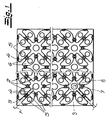
- the figures show a pipe receiving plate according to the invention made of plastic, which is provided for receiving fluid-flowed pipes 1, in particular of heating pipes.
- the plate has molded-on tube receiving elements, which are expediently and in the exemplary embodiment in the form of nubs 2. These nubs 2 or the channels 3 arranged between the nubs 2 are set up for a clamping retention of the tubes 1.
- the plate further comprises sleepers 4 integrally formed on the bottom, which are arranged between the studs 2 and hold a tube 1 inserted into the studded surface as spacer elements with a bottom-side spacing from the support surface of the plate.
- the nubs 2 are hollow inside and thus as it were formed as wells that are open at the bottom.
- the plate passing through openings 5 are provided.
- Fig. 1 It can be seen that at least some of these openings 5 are provided in the nub surfaces, namely in the nubber tops 6 in the exemplary embodiment.
- openings 5 centrally located in these knob tops 6.
- the plate shown here is suitable in particular for laying the pipes on a floor / floor or on a ceiling.
- the central-central arrangement of the openings 5 ensures that a subsequently applied mass, not shown, for example, a screed mass, evenly distributed in the nubs 2 and the nubs 2 fills as completely as possible.
- the plate according to the invention is made transparent, so that one can recognize the background or background with the naked eye through the plate.
- the plate consists of a polyester, preferably of polyethylene terephthalate (PETP).
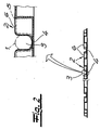
- a fastening element 7 is inserted with a fixing end 9 having a fastening opening 8 between the nubs 2 of the plate, so that the fastening opening 8 of this fastening end 9 is arranged above an aperture 5 passing through the plate.
- a fixing means such as a nail or an anchor can be inserted through the mounting hole 8 and the opening 5 in the ground, without the plate is damaged.
- the second attachment end 9 of the fastener 7 By inserting the second attachment end 9 of the fastener 7 in an appropriate manner into an adjacent plate, the two adjacent plates can be effectively connected.
- - Fig. 3 shows, moreover, an inventive fastening element 7 with two attachment openings 8 each having a fastening end 9.
- the fastening element 7 has in Fig. 3 and preferably a bone shape.
Claims (10)
- Plaque de montage de tubes, réalisée en matière plastique, pour le logement de tubes (1) de passage de fluides, en particulier de tubes de chauffage, la plaque comportant des éléments conformés pour le logement des tubes, caractérisée en ce que la plaque a une réalisation transparente au moins par zones.
- Plaque de montage de tubes suivant la revendication 1, caractérisée en ce que les éléments de logement de tubes sont conçus pour une fixation par coinçage des tubes (1).
- Plaque de montage de tubes suivant l'une des revendications 1 et 2, caractérisée en ce que les éléments de logement de tubes sont configurés sous forme de nopes (2), et que des canaux (3) pour le logement des tubes (3) sont prévus entre les nopes (2).
- Plaque de montage de tubes suivant l'une des revendications 1 à 3, caractérisée en ce qu'il est prévu une pluralité d'ouvertures (5) traversant la plaque.
- Plaque de montage de tubes suivant l'une des revendications 1 à 4, caractérisée en ce qu'au moins une partie des ouvertures (5) est prévue dans les surfaces des nopes, de préférence dans les côtés supérieurs (6) des nopes.
- Plaque de montage de tubes suivant la revendication 5, caractérisée en ce qu'au moins une partie des ouvertures (5) est disposée de façon centrale dans les côtés supérieurs (6) des nopes.
- Plaque de montage de tubes suivant la revendication 5, caractérisée en ce qu'au moins une partie des ouvertures (5) est disposée de façon excentrée par rapport au centre du côté supérieur (6) des nopes.
- Plaque de montage de tubes suivant l'une des revendications 1 à 7, caractérisée en ce que la plaque se compose d'un polyester.
- Plaque de montage de tubes suivant la revendication 8, caractérisée en ce que la plaque se compose de polyéthylènetéréphatalate (PETP).
- Groupe constitué d'une plaque de montage de tubes suivant l'une des revendications 4 à 9 et d'un élément de fixation (7), caractérisé en ce que l'élément de fixation (7) est prévu avec deux extrémités de fixation (9) comportant chacune une ouverture de fixation (8), une extrémité de fixation (9) étant insérée entre les nopes (2) de la plaque, de sorte que l'ouverture de fixation (8) de cette extrémité de fixation (9) est disposée au-dessus d'une ouverture (5) traversant la plaque.
Priority Applications (7)
| Application Number | Priority Date | Filing Date | Title |
|---|---|---|---|
| SI200331131T SI1531306T1 (sl) | 2003-11-12 | 2003-11-12 | Plasticna plosca za montažo cevi, v kateri cirkulira tekocina |
| PT03025900T PT1531306E (pt) | 2003-11-12 | 2003-11-12 | Placa de plástico para recepção de tubos destinada a incorporar tubos percorridos por fluidos |
| AT03025900T ATE386239T1 (de) | 2003-11-12 | 2003-11-12 | Rohraufnahmeplatte aus kunststoff für eine aufnahme von fluiddurchströmten rohren |
| EP03025900A EP1531306B1 (fr) | 2003-11-12 | 2003-11-12 | Plaque en plastique pour le montage de tubes dans lesquels circule un fluide |
| DK03025900T DK1531306T3 (da) | 2003-11-12 | 2003-11-12 | Röroptagelsesplade af kunststof til optagelse af fluidgennemströmmede rör |
| ES03025900T ES2297089T3 (es) | 2003-11-12 | 2003-11-12 | Placa de montaje de tubos de plastico para el alojamiento de tubos por los que circula una corriente de fluido. |
| DE50309167T DE50309167D1 (de) | 2003-11-12 | 2003-11-12 | Rohraufnahmeplatte aus Kunststoff für eine Aufnahme von fluiddurchströmten Rohren |
Applications Claiming Priority (1)
| Application Number | Priority Date | Filing Date | Title |
|---|---|---|---|
| EP03025900A EP1531306B1 (fr) | 2003-11-12 | 2003-11-12 | Plaque en plastique pour le montage de tubes dans lesquels circule un fluide |
Publications (2)
| Publication Number | Publication Date |
|---|---|
| EP1531306A1 EP1531306A1 (fr) | 2005-05-18 |
| EP1531306B1 true EP1531306B1 (fr) | 2008-02-13 |
Family
ID=34429330
Family Applications (1)
| Application Number | Title | Priority Date | Filing Date |
|---|---|---|---|
| EP03025900A Expired - Lifetime EP1531306B1 (fr) | 2003-11-12 | 2003-11-12 | Plaque en plastique pour le montage de tubes dans lesquels circule un fluide |
Country Status (7)
| Country | Link |
|---|---|
| EP (1) | EP1531306B1 (fr) |
| AT (1) | ATE386239T1 (fr) |
| DE (1) | DE50309167D1 (fr) |
| DK (1) | DK1531306T3 (fr) |
| ES (1) | ES2297089T3 (fr) |
| PT (1) | PT1531306E (fr) |
| SI (1) | SI1531306T1 (fr) |
Cited By (2)
| Publication number | Priority date | Publication date | Assignee | Title |
|---|---|---|---|---|
| EP2260247B1 (fr) | 2008-02-26 | 2016-06-08 | M=Eco² Cvba | Construction multicouche comprenant un systeme de tubes |
| US11846432B2 (en) | 2009-08-28 | 2023-12-19 | Progress Profiles Spa | Method and apparatus for positioning heating elements |
Families Citing this family (6)
| Publication number | Priority date | Publication date | Assignee | Title |
|---|---|---|---|---|
| ITBO20130014A1 (it) * | 2013-01-15 | 2014-07-16 | Biopack Srl | Pannello per impianti radianti a pavimento |
| US9625163B2 (en) | 2014-08-18 | 2017-04-18 | Progress Profiles Spa | Method and apparatus for positioning heating elements |
| US9726383B1 (en) | 2016-06-17 | 2017-08-08 | Progress Profiles S.P.A. | Support for radiant covering and floor heating elements |
| US10859274B2 (en) | 2016-04-01 | 2020-12-08 | Progress Profiles S.P.A. | Support for radiant covering and floor heating elements |
| USD971449S1 (en) | 2016-04-13 | 2022-11-29 | Progress Profiles S.P.A. | Floor underlayment |
| EP3324128B1 (fr) * | 2016-11-21 | 2019-01-02 | Regatherm GmbH | Dispositif et méthode pour tempérer des planchers ou des murs dans des bâtiments en diminuant la génération de chaleur indésirable dans la zone des tubes de liaison et montage |
Family Cites Families (8)
| Publication number | Priority date | Publication date | Assignee | Title |
|---|---|---|---|---|
| BE860569A (fr) * | 1977-05-06 | 1978-03-01 | Feist Artus | Plaque de montage servant a fixer des tuyaux flexibles de chauffage ou de refroidissement |
| AT362913B (de) * | 1979-07-20 | 1981-06-25 | Feist Artus | Einrichtung zur waermeisolation und gleichzeitigen waermeenergiegewinnung bei einem gebaeude |
| DE8703788U1 (fr) * | 1987-03-10 | 1987-05-07 | Feist, Artus, 5060 Bergisch Gladbach, De | |
| DE3837562C2 (de) * | 1988-11-04 | 1997-11-20 | Eht Siegmund Gmbh | Flächenelement für einen beheizbaren Hohlraumboden |
| DE9002358U1 (fr) * | 1990-02-28 | 1990-05-03 | Balsam Ag, 4803 Steinhagen, De | |
| DE59200894D1 (de) * | 1991-05-24 | 1995-01-19 | Bruno Lampka | Montageplatte für Schlauchleitungen. |
| DE9109512U1 (fr) * | 1991-06-28 | 1991-11-07 | Feist, Artus, 5210 Troisdorf, De | |
| DE29916642U1 (de) * | 1999-09-21 | 2000-01-05 | Siegmund Helmut | Distanzplatte für einen Hohlraumboden und Hohlraumboden |
-
2003
- 2003-11-12 DK DK03025900T patent/DK1531306T3/da active
- 2003-11-12 SI SI200331131T patent/SI1531306T1/sl unknown
- 2003-11-12 DE DE50309167T patent/DE50309167D1/de not_active Expired - Lifetime
- 2003-11-12 AT AT03025900T patent/ATE386239T1/de active
- 2003-11-12 ES ES03025900T patent/ES2297089T3/es not_active Expired - Lifetime
- 2003-11-12 PT PT03025900T patent/PT1531306E/pt unknown
- 2003-11-12 EP EP03025900A patent/EP1531306B1/fr not_active Expired - Lifetime
Cited By (2)
| Publication number | Priority date | Publication date | Assignee | Title |
|---|---|---|---|---|
| EP2260247B1 (fr) | 2008-02-26 | 2016-06-08 | M=Eco² Cvba | Construction multicouche comprenant un systeme de tubes |
| US11846432B2 (en) | 2009-08-28 | 2023-12-19 | Progress Profiles Spa | Method and apparatus for positioning heating elements |
Also Published As
| Publication number | Publication date |
|---|---|
| ES2297089T3 (es) | 2008-05-01 |
| SI1531306T1 (sl) | 2008-04-30 |
| ATE386239T1 (de) | 2008-03-15 |
| DK1531306T3 (da) | 2008-06-16 |
| EP1531306A1 (fr) | 2005-05-18 |
| DE50309167D1 (de) | 2008-04-03 |
| PT1531306E (pt) | 2008-06-26 |
Similar Documents
| Publication | Publication Date | Title |
|---|---|---|
| EP0769659B1 (fr) | Elément de contact et élément de plafond pour chauffage ou refroidissement par le plafond | |
| DE2310333A1 (de) | Wandanordnung bestehend aus einem inneren wandteil und einem aeusseren wandteil, die mit abstand voneinander angeordnet sind | |
| DE10040643C1 (de) | Verlegevorrichtung für Kühl- oder Heizmedium führende Rohre | |
| DE3207960A1 (de) | Heizelement, insbesondere als fussboden oder fussbodenelement, und verfahren zur herstellung eines solchen | |
| EP1531306B1 (fr) | Plaque en plastique pour le montage de tubes dans lesquels circule un fluide | |
| DE3109866C2 (de) | Verlegeplatte zum flächigen Verlegen von Rohrleitungen, insbesondere bei einer Fußbodenheizung | |
| EP1332318A1 (fr) | Plaque a poser modulaire utilisee dans des systemes de chauffage par plancher ou par mur et toles thermoconductrices associees | |
| DE10313076B3 (de) | Verlegevorrichtung für Kühl- oder Heizmedien führende Rohre einer Flächentemperiervorrichtung | |
| DE2713251C2 (de) | Großflächenheizung | |
| EP0102408B1 (fr) | Elément d'isolation | |
| EP1118730B1 (fr) | Espaceur de renforcement positionnant des barres d'armature vis à vis d'un coffrage pour constructions de béton | |
| DE102009032203A1 (de) | Außenwandsystem | |
| DE2456836A1 (de) | Verfahren zur verlegung einer heizrohr-anordnung auf flaechen | |
| EP0000484B1 (fr) | Elément de montage pour chauffage superficiel par liquide. | |
| EP3473773B1 (fr) | Élément de paroi destiné à l'utilisation dans un dispositif de rétention d'eau ainsi que dispositif de rétention d'eau | |
| DE202011106736U1 (de) | Plattenelement zur Erzeugung von Flächenheizungen | |
| AT8931U1 (de) | Bodenaufbau mit auf stützen verlegten platten | |
| DE202013007360U1 (de) | Befestigungsvorrichtung für die Rohre einer Fußbodenheizung | |
| DE3837564C2 (de) | Hohlraumboden | |
| DE2742429A1 (de) | Montageplatte fuer heiz- und kuehlmittelschlaeuche und deren verwendung | |
| DE202009000976U1 (de) | Mehrschichtige Platte und Wärmeleitplatte | |
| WO1998005905A1 (fr) | Panneau de chauffage ou de refroidissement a tubes capillaires pourvu d'une mince couche de couverture en ciment | |
| DE2850196A1 (de) | Vorgefertigte fussbodenplatten mit heizkanaelen fuer heizrohre | |
| DE102007039469B4 (de) | Systemplatte zum Verlegen von Kunststoffrohren der Heiz- bzw. Kühlkreise von Flächen-Heiz- und Kühlinstallationen | |
| EP2090837B1 (fr) | Plaque de matériau isolant pour tuyaux de chauffage et/ou de refroidissement |
Legal Events
| Date | Code | Title | Description |
|---|---|---|---|
| PUAI | Public reference made under article 153(3) epc to a published international application that has entered the european phase |
Free format text: ORIGINAL CODE: 0009012 |
|
| 17P | Request for examination filed |
Effective date: 20040423 |
|
| AK | Designated contracting states |
Kind code of ref document: A1 Designated state(s): AT BE BG CH CY CZ DE DK EE ES FI FR GB GR HU IE IT LI LU MC NL PT RO SE SI SK TR |
|
| AX | Request for extension of the european patent |
Extension state: AL LT LV MK |
|
| AKX | Designation fees paid |
Designated state(s): AT BE BG CH CY CZ DE DK EE ES FI FR GB GR HU IE IT LI LU MC NL PT RO SE SI SK TR |
|
| GRAP | Despatch of communication of intention to grant a patent |
Free format text: ORIGINAL CODE: EPIDOSNIGR1 |
|
| GRAS | Grant fee paid |
Free format text: ORIGINAL CODE: EPIDOSNIGR3 |
|
| GRAA | (expected) grant |
Free format text: ORIGINAL CODE: 0009210 |
|
| STAA | Information on the status of an ep patent application or granted ep patent |
Free format text: STATUS: THE PATENT HAS BEEN GRANTED |
|
| AK | Designated contracting states |
Kind code of ref document: B1 Designated state(s): AT BE BG CH CY CZ DE DK EE ES FI FR GB GR HU IE IT LI LU MC NL PT RO SE SI SK TR |
|
| REG | Reference to a national code |
Ref country code: GB Ref legal event code: FG4D Free format text: NOT ENGLISH |
|
| REG | Reference to a national code |
Ref country code: CH Ref legal event code: EP |
|
| REG | Reference to a national code |
Ref country code: IE Ref legal event code: FG4D Free format text: LANGUAGE OF EP DOCUMENT: GERMAN |
|
| REF | Corresponds to: |
Ref document number: 50309167 Country of ref document: DE Date of ref document: 20080403 Kind code of ref document: P |
|
| REG | Reference to a national code |
Ref country code: ES Ref legal event code: FG2A Ref document number: 2297089 Country of ref document: ES Kind code of ref document: T3 |
|
| REG | Reference to a national code |
Ref country code: SE Ref legal event code: TRGR |
|
| REG | Reference to a national code |
Ref country code: DK Ref legal event code: T3 |
|
| REG | Reference to a national code |
Ref country code: PT Ref legal event code: SC4A Free format text: AVAILABILITY OF NATIONAL TRANSLATION Effective date: 20080616 |
|
| NLV1 | Nl: lapsed or annulled due to failure to fulfill the requirements of art. 29p and 29m of the patents act | ||
| REG | Reference to a national code |
Ref country code: IE Ref legal event code: FD4D |
|
| ET | Fr: translation filed | ||
| REG | Reference to a national code |
Ref country code: HU Ref legal event code: AG4A Ref document number: E003580 Country of ref document: HU |
|
| PG25 | Lapsed in a contracting state [announced via postgrant information from national office to epo] |
Ref country code: SK Free format text: LAPSE BECAUSE OF FAILURE TO SUBMIT A TRANSLATION OF THE DESCRIPTION OR TO PAY THE FEE WITHIN THE PRESCRIBED TIME-LIMIT Effective date: 20080213 Ref country code: NL Free format text: LAPSE BECAUSE OF FAILURE TO SUBMIT A TRANSLATION OF THE DESCRIPTION OR TO PAY THE FEE WITHIN THE PRESCRIBED TIME-LIMIT Effective date: 20080213 Ref country code: IE Free format text: LAPSE BECAUSE OF FAILURE TO SUBMIT A TRANSLATION OF THE DESCRIPTION OR TO PAY THE FEE WITHIN THE PRESCRIBED TIME-LIMIT Effective date: 20080213 |
|
| PG25 | Lapsed in a contracting state [announced via postgrant information from national office to epo] |
Ref country code: RO Free format text: LAPSE BECAUSE OF FAILURE TO SUBMIT A TRANSLATION OF THE DESCRIPTION OR TO PAY THE FEE WITHIN THE PRESCRIBED TIME-LIMIT Effective date: 20080213 |
|
| PLBE | No opposition filed within time limit |
Free format text: ORIGINAL CODE: 0009261 |
|
| STAA | Information on the status of an ep patent application or granted ep patent |
Free format text: STATUS: NO OPPOSITION FILED WITHIN TIME LIMIT |
|
| 26N | No opposition filed |
Effective date: 20081114 |
|
| PG25 | Lapsed in a contracting state [announced via postgrant information from national office to epo] |
Ref country code: BG Free format text: LAPSE BECAUSE OF FAILURE TO SUBMIT A TRANSLATION OF THE DESCRIPTION OR TO PAY THE FEE WITHIN THE PRESCRIBED TIME-LIMIT Effective date: 20080513 Ref country code: EE Free format text: LAPSE BECAUSE OF FAILURE TO SUBMIT A TRANSLATION OF THE DESCRIPTION OR TO PAY THE FEE WITHIN THE PRESCRIBED TIME-LIMIT Effective date: 20080213 |
|
| PG25 | Lapsed in a contracting state [announced via postgrant information from national office to epo] |
Ref country code: MC Free format text: LAPSE BECAUSE OF NON-PAYMENT OF DUE FEES Effective date: 20081130 |
|
| PGFP | Annual fee paid to national office [announced via postgrant information from national office to epo] |
Ref country code: SI Payment date: 20081103 Year of fee payment: 6 |
|
| REG | Reference to a national code |
Ref country code: CH Ref legal event code: PL |
|
| PG25 | Lapsed in a contracting state [announced via postgrant information from national office to epo] |
Ref country code: CY Free format text: LAPSE BECAUSE OF FAILURE TO SUBMIT A TRANSLATION OF THE DESCRIPTION OR TO PAY THE FEE WITHIN THE PRESCRIBED TIME-LIMIT Effective date: 20080213 |
|
| PG25 | Lapsed in a contracting state [announced via postgrant information from national office to epo] |
Ref country code: LI Free format text: LAPSE BECAUSE OF NON-PAYMENT OF DUE FEES Effective date: 20081130 Ref country code: CH Free format text: LAPSE BECAUSE OF NON-PAYMENT OF DUE FEES Effective date: 20081130 |
|
| PGFP | Annual fee paid to national office [announced via postgrant information from national office to epo] |
Ref country code: HU Payment date: 20081030 Year of fee payment: 6 |
|
| PG25 | Lapsed in a contracting state [announced via postgrant information from national office to epo] |
Ref country code: HU Free format text: LAPSE BECAUSE OF NON-PAYMENT OF DUE FEES Effective date: 20091113 Ref country code: LU Free format text: LAPSE BECAUSE OF NON-PAYMENT OF DUE FEES Effective date: 20081112 |
|
| PG25 | Lapsed in a contracting state [announced via postgrant information from national office to epo] |
Ref country code: TR Free format text: LAPSE BECAUSE OF FAILURE TO SUBMIT A TRANSLATION OF THE DESCRIPTION OR TO PAY THE FEE WITHIN THE PRESCRIBED TIME-LIMIT Effective date: 20080213 |
|
| REG | Reference to a national code |
Ref country code: SI Ref legal event code: KO00 Effective date: 20100716 |
|
| PG25 | Lapsed in a contracting state [announced via postgrant information from national office to epo] |
Ref country code: SI Free format text: LAPSE BECAUSE OF NON-PAYMENT OF DUE FEES Effective date: 20091113 |
|
| PG25 | Lapsed in a contracting state [announced via postgrant information from national office to epo] |
Ref country code: GR Free format text: LAPSE BECAUSE OF NON-PAYMENT OF DUE FEES Effective date: 20081130 |
|
| PGFP | Annual fee paid to national office [announced via postgrant information from national office to epo] |
Ref country code: IT Payment date: 20121127 Year of fee payment: 10 |
|
| PGFP | Annual fee paid to national office [announced via postgrant information from national office to epo] |
Ref country code: PT Payment date: 20130513 Year of fee payment: 11 Ref country code: GB Payment date: 20131120 Year of fee payment: 11 Ref country code: CZ Payment date: 20131108 Year of fee payment: 11 |
|
| PG25 | Lapsed in a contracting state [announced via postgrant information from national office to epo] |
Ref country code: IT Free format text: LAPSE BECAUSE OF NON-PAYMENT OF DUE FEES Effective date: 20131112 |
|
| REG | Reference to a national code |
Ref country code: PT Ref legal event code: MM4A Free format text: LAPSE DUE TO NON-PAYMENT OF FEES Effective date: 20150512 |
|
| GBPC | Gb: european patent ceased through non-payment of renewal fee |
Effective date: 20141112 |
|
| PG25 | Lapsed in a contracting state [announced via postgrant information from national office to epo] |
Ref country code: CZ Free format text: LAPSE BECAUSE OF NON-PAYMENT OF DUE FEES Effective date: 20141112 Ref country code: PT Free format text: LAPSE BECAUSE OF NON-PAYMENT OF DUE FEES Effective date: 20150512 |
|
| PG25 | Lapsed in a contracting state [announced via postgrant information from national office to epo] |
Ref country code: GB Free format text: LAPSE BECAUSE OF NON-PAYMENT OF DUE FEES Effective date: 20141112 |
|
| REG | Reference to a national code |
Ref country code: FR Ref legal event code: PLFP Year of fee payment: 13 |
|
| PGFP | Annual fee paid to national office [announced via postgrant information from national office to epo] |
Ref country code: DE Payment date: 20151117 Year of fee payment: 13 Ref country code: DK Payment date: 20151118 Year of fee payment: 13 Ref country code: FI Payment date: 20151111 Year of fee payment: 13 |
|
| PGFP | Annual fee paid to national office [announced via postgrant information from national office to epo] |
Ref country code: FR Payment date: 20151119 Year of fee payment: 13 Ref country code: SE Payment date: 20151118 Year of fee payment: 13 Ref country code: ES Payment date: 20151111 Year of fee payment: 13 Ref country code: BE Payment date: 20151118 Year of fee payment: 13 Ref country code: AT Payment date: 20151119 Year of fee payment: 13 |
|
| PG25 | Lapsed in a contracting state [announced via postgrant information from national office to epo] |
Ref country code: BE Free format text: LAPSE BECAUSE OF NON-PAYMENT OF DUE FEES Effective date: 20161130 |
|
| REG | Reference to a national code |
Ref country code: DE Ref legal event code: R119 Ref document number: 50309167 Country of ref document: DE |
|
| REG | Reference to a national code |
Ref country code: DK Ref legal event code: EBP Effective date: 20161130 |
|
| REG | Reference to a national code |
Ref country code: SE Ref legal event code: EUG |
|
| REG | Reference to a national code |
Ref country code: AT Ref legal event code: MM01 Ref document number: 386239 Country of ref document: AT Kind code of ref document: T Effective date: 20161112 |
|
| PG25 | Lapsed in a contracting state [announced via postgrant information from national office to epo] |
Ref country code: FI Free format text: LAPSE BECAUSE OF NON-PAYMENT OF DUE FEES Effective date: 20161112 |
|
| REG | Reference to a national code |
Ref country code: FR Ref legal event code: ST Effective date: 20170731 |
|
| PG25 | Lapsed in a contracting state [announced via postgrant information from national office to epo] |
Ref country code: AT Free format text: LAPSE BECAUSE OF NON-PAYMENT OF DUE FEES Effective date: 20161112 Ref country code: SE Free format text: LAPSE BECAUSE OF NON-PAYMENT OF DUE FEES Effective date: 20161113 |
|
| PG25 | Lapsed in a contracting state [announced via postgrant information from national office to epo] |
Ref country code: FR Free format text: LAPSE BECAUSE OF NON-PAYMENT OF DUE FEES Effective date: 20161130 |
|
| PG25 | Lapsed in a contracting state [announced via postgrant information from national office to epo] |
Ref country code: DE Free format text: LAPSE BECAUSE OF NON-PAYMENT OF DUE FEES Effective date: 20170601 Ref country code: DK Free format text: LAPSE BECAUSE OF NON-PAYMENT OF DUE FEES Effective date: 20161130 |
|
| REG | Reference to a national code |
Ref country code: BE Ref legal event code: MM Effective date: 20161130 |
|
| PG25 | Lapsed in a contracting state [announced via postgrant information from national office to epo] |
Ref country code: ES Free format text: LAPSE BECAUSE OF NON-PAYMENT OF DUE FEES Effective date: 20161113 |
|
| REG | Reference to a national code |
Ref country code: ES Ref legal event code: FD2A Effective date: 20181121 |