EP1531247A2 - Elektromechanisches Regelungssystem, insbesondere für maritime Anwendungen - Google Patents
Elektromechanisches Regelungssystem, insbesondere für maritime Anwendungen Download PDFInfo
- Publication number
- EP1531247A2 EP1531247A2 EP04105033A EP04105033A EP1531247A2 EP 1531247 A2 EP1531247 A2 EP 1531247A2 EP 04105033 A EP04105033 A EP 04105033A EP 04105033 A EP04105033 A EP 04105033A EP 1531247 A2 EP1531247 A2 EP 1531247A2
- Authority
- EP
- European Patent Office
- Prior art keywords
- control
- beta
- lever
- signal
- monitoring unit
- Prior art date
- Legal status (The legal status is an assumption and is not a legal conclusion. Google has not performed a legal analysis and makes no representation as to the accuracy of the status listed.)
- Granted
Links
Images


Classifications
-
- F—MECHANICAL ENGINEERING; LIGHTING; HEATING; WEAPONS; BLASTING
- F02—COMBUSTION ENGINES; HOT-GAS OR COMBUSTION-PRODUCT ENGINE PLANTS
- F02D—CONTROLLING COMBUSTION ENGINES
- F02D41/00—Electrical control of supply of combustible mixture or its constituents
- F02D41/24—Electrical control of supply of combustible mixture or its constituents characterised by the use of digital means
- F02D41/2406—Electrical control of supply of combustible mixture or its constituents characterised by the use of digital means using essentially read only memories
- F02D41/2425—Particular ways of programming the data
-
- B—PERFORMING OPERATIONS; TRANSPORTING
- B63—SHIPS OR OTHER WATERBORNE VESSELS; RELATED EQUIPMENT
- B63H—MARINE PROPULSION OR STEERING
- B63H21/00—Use of propulsion power plant or units on vessels
- B63H21/21—Control means for engine or transmission, specially adapted for use on marine vessels
- B63H21/213—Levers or the like for controlling the engine or the transmission, e.g. single hand control levers
-
- F—MECHANICAL ENGINEERING; LIGHTING; HEATING; WEAPONS; BLASTING
- F02—COMBUSTION ENGINES; HOT-GAS OR COMBUSTION-PRODUCT ENGINE PLANTS
- F02D—CONTROLLING COMBUSTION ENGINES
- F02D11/00—Arrangements for, or adaptations to, non-automatic engine control initiation means, e.g. operator initiated
- F02D11/06—Arrangements for, or adaptations to, non-automatic engine control initiation means, e.g. operator initiated characterised by non-mechanical control linkages, e.g. fluid control linkages or by control linkages with power drive or assistance
- F02D11/10—Arrangements for, or adaptations to, non-automatic engine control initiation means, e.g. operator initiated characterised by non-mechanical control linkages, e.g. fluid control linkages or by control linkages with power drive or assistance of the electric type
- F02D11/105—Arrangements for, or adaptations to, non-automatic engine control initiation means, e.g. operator initiated characterised by non-mechanical control linkages, e.g. fluid control linkages or by control linkages with power drive or assistance of the electric type characterised by the function converting demand to actuation, e.g. a map indicating relations between an accelerator pedal position and throttle valve opening or target engine torque
-
- F—MECHANICAL ENGINEERING; LIGHTING; HEATING; WEAPONS; BLASTING
- F02—COMBUSTION ENGINES; HOT-GAS OR COMBUSTION-PRODUCT ENGINE PLANTS
- F02D—CONTROLLING COMBUSTION ENGINES
- F02D41/00—Electrical control of supply of combustible mixture or its constituents
- F02D41/22—Safety or indicating devices for abnormal conditions
-
- F—MECHANICAL ENGINEERING; LIGHTING; HEATING; WEAPONS; BLASTING
- F02—COMBUSTION ENGINES; HOT-GAS OR COMBUSTION-PRODUCT ENGINE PLANTS
- F02D—CONTROLLING COMBUSTION ENGINES
- F02D41/00—Electrical control of supply of combustible mixture or its constituents
- F02D41/24—Electrical control of supply of combustible mixture or its constituents characterised by the use of digital means
- F02D41/2406—Electrical control of supply of combustible mixture or its constituents characterised by the use of digital means using essentially read only memories
- F02D41/2409—Addressing techniques specially adapted therefor
- F02D41/2416—Interpolation techniques
-
- F—MECHANICAL ENGINEERING; LIGHTING; HEATING; WEAPONS; BLASTING
- F02—COMBUSTION ENGINES; HOT-GAS OR COMBUSTION-PRODUCT ENGINE PLANTS
- F02D—CONTROLLING COMBUSTION ENGINES
- F02D41/00—Electrical control of supply of combustible mixture or its constituents
- F02D41/24—Electrical control of supply of combustible mixture or its constituents characterised by the use of digital means
- F02D41/2406—Electrical control of supply of combustible mixture or its constituents characterised by the use of digital means using essentially read only memories
- F02D41/2409—Addressing techniques specially adapted therefor
- F02D41/2422—Selective use of one or more tables
-
- F—MECHANICAL ENGINEERING; LIGHTING; HEATING; WEAPONS; BLASTING
- F02—COMBUSTION ENGINES; HOT-GAS OR COMBUSTION-PRODUCT ENGINE PLANTS
- F02D—CONTROLLING COMBUSTION ENGINES
- F02D41/00—Electrical control of supply of combustible mixture or its constituents
- F02D41/24—Electrical control of supply of combustible mixture or its constituents characterised by the use of digital means
- F02D41/26—Electrical control of supply of combustible mixture or its constituents characterised by the use of digital means using computer, e.g. microprocessor
- F02D41/266—Electrical control of supply of combustible mixture or its constituents characterised by the use of digital means using computer, e.g. microprocessor the computer being backed-up or assisted by another circuit, e.g. analogue
-
- F—MECHANICAL ENGINEERING; LIGHTING; HEATING; WEAPONS; BLASTING
- F02—COMBUSTION ENGINES; HOT-GAS OR COMBUSTION-PRODUCT ENGINE PLANTS
- F02D—CONTROLLING COMBUSTION ENGINES
- F02D41/00—Electrical control of supply of combustible mixture or its constituents
- F02D41/22—Safety or indicating devices for abnormal conditions
- F02D2041/228—Warning displays
Definitions
- the present invention relates to an electromechanical control system for watercrafts, motorboats, ships or the like, having at least: a control station, an engine, an electromechanical actuator associated to said engine, a signal transmission device for transmitting a control signal generated by the control station to an electronic control and monitoring unit, and further having a signal transmission device for transmitting an actuating signal, generated by the electronic control and monitoring unit as a function of the control signal and transmitted to said electromechanical actuator for actuating the control.
- a control signal set by the user from the control device e.g. a control lever, which control device allows a mechanical or electromechanical control, for instance, of the throttle or a fuel flow meter device for controlling flow to the watercraft engine, causes the throttle to open and a higher flow of fuel to reach the engine.
- the greater fuel flow causes the engine to increase the number of its operating revolutions per minute and, as a result, its power.
- the opening of the throttle and/or the increased fuel flow generated by the flow meter device causing a corresponding increase of the engine's rpm, does not linearly correspond to an increase of the power delivered by the engine, because no linear relationship exists between power and fuel delivery in the equation that regulates engine operation.
- their relationship is of the nonlinear type and differs from linearity especially in multiple cylinder gasoline and diesel engines.
- a control corresponding for instance to 50% of the maximum control lever range does not cause a proportional 50% increase of the delivered power, which may be higher or lower depending, as mentioned above, on additional parameters, such as the number of revolutions at which the throttle opens.
- the angular displacement of the control lever may lead to an increase of the delivered power that may considerably differ from one situation to the other, and this may affect an easy control of the watercraft.
- the delivered power may be controlled while maneuvering, but at the maximum angular displacement of the control lever it does not correspond to the maximum fuel flow delivered by the flow meter device and/or by the throttle.
- This kind of control is simple but poorly effective, as the relationship between the displacement of the control lever and the opening of the throttle and/or flow meter device is still linear, which causes a non linearity of the power delivered to the engine, for the above reasons.
- the above problems are not solved by prior art, which only reduces the maximum opening of the throttle, to allow the user to have an easier, but not optimized control of the watercraft.
- nonlinear power delivery cause problems not only during maneuvers, but also in offshore navigation; it may be easily understood that serious problems may arise whenever a total control of the watercraft is needed, such as when other vessels are encountered, in rough sea conditions, or the like.
- the normal delivery obtained in prior art systems does not allow to configure the maximum opening that may be reached by the throttle and/or the maximum fuel flow delivered by the fuel flow meter device, at the maximum control lever displacement, with a variable profile.
- prior art systems do not allow to set the delivery in "power saving" drive conditions, in which the throttle has an 80% maximum opening, allowing to save fuel and reduce the wear of the engine.
- the nonlinearity between the control set by the control lever and the delivered power in prior art systems further involves a number of other drawbacks, associated for instance to the difficulties encountered by inexperienced pilots of watercrafts: an inexpert user may easily make evaluation errors, and as a consequence, driving errors, which may lead to unexpected consequences; consider, for instance, a user who is learning how to drive, and during a narrow turn, inadvertently displaces the control lever and causes a sudden and unexpected engine power increase. Due to such errors, an inexperienced user may lose the control of the watercraft, which may lead to easily guessable consequences.
- Prior art apparatuses further have a drawback which is associated to the fact that, when the direction of the propeller rotation is reversed, by a backward displacement of the control lever, the opening of the throttle is linear with the backward displacement of the control lever, whereby the user who has to deal with the above discussed nonlinear delivery, is subjected to the same drawbacks as mentioned above, and to the additional problem that the watercraft is, for instance, moving astern, and is difficult to maneuver.
- the object of the present invention is to provide an electromechanical control system, particularly for marine applications, according to the preamble of claim 1, which may simply and inexpensively obviate the drawbacks of prior art electromechanical control systems, particularly for marine applications.
- the invention fulfils the above objects by providing an electromechanical control system for watercrafts, motorboats, ships or the like, having at least: a control station, an engine, an electromechanical actuator associated to said engine, a signal transmission device for transmitting a control signal generated by the control station to an electronic control and monitoring unit as a function of the control signal and transmitted to said electromechanical actuator for actuating the signal, and further having a signal transmission device for transmitting an actuating signal, generated by the electronic control and monitoring unit as a function of the control signal and transmitted to said electromechanical actuator for actuating the control, characterized in that said electronic control and monitoring unit establishes a unique correspondence between the control signal and the actuating signal by using a table of correspondence between discretized values of control signals and actuating signals and/or by determining the actuating signal value from the control signal by means of a mathematical function.
- the invention includes a control station associated to a control device for the user to set a control signal, said control setting device being able to be displaced relative to a fixed reference, its displacement being related to a control signal value, with electric, electronic and/or electromechanical means being associated to said control device, for detecting the displacement of the control device and for generating a control signal that is uniquely related with said displacement.
- the control device is provided in the form of a lever that pivots about a fulcrum, having known systems for electric/electronic detection of the angular displacement (BETA) of the lever, which is turned into an electric/electronic control signal.
- Such control signal is transmitted to the programmable electronic control and monitoring unit through said signal transmission devices in the form of a CAN BUS.
- the electronic control and monitoring unit stores one or more tables of unique correlation between the control signal corresponding to the angular position (BETA) of the control lever and the actuating signal corresponding to the angular position (ALFA) of the actuating lever and/or the flow meter or control device.
- the electronic control unit stores, in the form of a program code to be executed thereby, one or more different functions of unique correlation between the control signal corresponding to the angular position (BETA) of the control lever and the actuating signal corresponding to the angular position (ALFA) of the actuating lever and/or the flow meter or control device, the corresponding actuating signal being determined from time to time, for each control signal, by using one of said correlation functions.
- the actuating signal so generated by the electronic control and monitoring unit is transmitted by the electronic control and monitoring unit to said actuator through the signal transmission devices, preferably in the form of a CAN bus.
- the actuator has a pivoting actuating lever which acts on the device for delivering fuel and/or fuel-air mixture of/to the engine and/or on a flow meter or control device having a flow metering or controlling member that can be angularly displaced about a predetermined axis, which lever and/or which flow meter or control device take a predetermined angular position (ALFA) relative to a stationary reference, as a function of the angular position (BETA) of the control lever relative to the corresponding stationary reference.
- ALFA predetermined angular position
- BETA angular position
- a memory may be preferably associated to said electronic control unit, preferably a nonvolatile memory, and means for loading in such memory one or more correlation functions f(BETA) and/or tables of correspondence between the angle of the actuating lever and/or of the flow meter or control device and/or of a throttle (ALFA) and the angle (BETA) of a control lever.
- the mathematical function f(BETA) is such that, given an angular displacement BETA, the displacement angle ALFA is determined as a result of the computation, by entering the BETA value in the function.
- the angular displacement of the control lever may be physically linked to the angular displacement of the throttle controlling lever even in a nonlinear manner, for instance according to a parabolic or hyperbolic function or a mathematical rule which produces any function whatever.
- the actual result of the invention is that the throttle opening may be perfectly programmable as a function of the control lever displacement angle.
- preset tables of correspondence may be used, which may be loaded into the memory of the electronic control and monitoring unit, to make any correspondence whatever between BETA and ALFA, by associating any BETA value to a corresponding ALFA value, while possibly providing a linear interpolation between the preset values.
- the operation of the inventive system is as follows: the user actuates the control device, e.g. the control lever, and the control signal so generated, i.e. the angular displacement BETA of the control lever is received by usual electric, electronic or electromechanical systems and is preferably digitized and transmitted through a CAN bus to the electronic control and monitoring unit.
- the electronic control and monitoring unit computes the preset function and provides, as a result of such computation, a control signal to be transferred, still preferably through a CAN bus, to the actuator, which accordingly actuates the fuel flow meter or control device and/or the throttle of the engine.
- the displacement of the control lever may trigger any power response engine, possibly a nonlinear response.
- At least one table of correspondence between the control signal value BETA and the actuating signal value ALFA is stored in a preferably nonvolatile memory of the electronic control and monitoring unit.
- the actuating signal is generated by a comparison in the table of correspondence by entering the BETA value therein.
- the BETA value and the corresponding ALFA value may be further freely interpolated between two predetermined values when they have not been previously stored in the electronic control and monitoring unit.
- a variety of mathematical functions may be stored in the nonvolatile memory associated to said electronic control unit, and the setting, i.e. the selection of the mathematical function or the table of correspondence is preferably effected by using selectors, whose various combinations correspond to different mathematical functions and/or tables of correspondence which relate ALFA and BETA.
- selectors are preferably a set of DIP switches. A certain number of combinations of switching conditions of the switches of the set is uniquely related as a selection code with one of the various correlation functions f (BETA) or a different table of correspondence, furthermore each switching combination of the set of DIP switches provides a control to load said corresponding correlation function or correlation table in the working storage of the control electronics.
- the memory of the electronic control and monitoring unit may be further adapted to be reprogrammed several times. Therefore, the user may select beforehand a desired kind of drive by setting the correspondence between ALFA and BETA given by the different functions, which corresponds to a different power response behavior of the engine, hence a different behavior of the watercraft.
- the user decides the desired function and/or table of correspondence by selecting an appropriate combination of DIP switches, hence the table and/or the function will be loaded by the electronic control and monitoring unit in the working storage.
- a predetermined function for instance, may be provided and programmed for maneuvering, in which, while providing a perfect linearity between the angular displacement of the control lever and the delivered power, the maximum delivered power may be arranged to be 30% of the maximum power delivered by the engine. This allows to obviate prior art problems associated to nonlinear power delivery, which affect the ease of drive.
- a "power saving" drive function might be further programmed in the electronic control unit, which corresponds, for instance, to a maximum throttle opening equal to 80% of the maximum opening, or equal to 80% of the maximum deliverable power, and a user selected profile may be provided, to allow a power saving drive, with consequent fuel savings, a lower engine wear, and an effective control of the delivered power.
- this invention allows to program and set several different watercraft acceleration profiles, to configure a wholly customized watercraft drive, which may be hence adapted to a number of different requirements.
- a function may be programmed and set whereby a 50% displacement of the control lever involves a linear increase of the delivered power of up to 30% of the maximum power, and a 50% to 100% displacement of the control lever involves a power increase of 30% to 100%, or less, of the maximum deliverable power.
- Such delivering arrangement provides a very smooth control of the watercraft at low speeds, which is particularly useful in coastwise navigation, where other vessels, swimmers or divers are very likely to be encountered and where an accurate control of the watercraft is imperative.
- f'(BETA) may be programmed and set, exactly like the functions f(BETA), to be used when the displacement of the control lever has a negative value.
- a fore displacement of the control lever causes a forward motion of the watercraft, due to the actuator-controlled opening of the throttle, whereas an aft displacement of the control lever triggers an inverter, which drives the propeller in reverse rotation, so that the watercraft is pushed backwards due to the reverse rotation of the propeller and to the opening of the throttle.
- the angular displacement BETA of the control lever is negative.
- This negative displacement may be associated, thanks to the electronic control and monitoring unit of this invention, to a function f' (BETA) that is different from f (BETA) , for instance programmed in such a manner that the reversing maneuver of the watercraft is facilitated, with an enhanced linearity in the first portion of the control lever range and a maximum deliverable power of less than 100%.
- the drive is thus dramatically facilitated as compared with prior art systems, in which the acceleration of the watercraft in reverse motion was essentially equal to forward motion acceleration.
- the electronic control and monitoring unit may be designed to monitor signal transmission from the control station to the throttle actuator. This allows to overcome the above mentioned prior art problems associated to a lack of the monitoring capability.
- the electronic control and monitoring unit monitors the communication and, when a wrong signal or a lack of signal is detected in the control station, the electronic control unit brings the throttle controlling lever in the minimum opening condition, and the inverter is brought in the neutral position, while the user receives an error warning by optical and/or acoustic signals.
- the throttle controlling lever remains in the minimum opening condition and the inverter remains in the neutral position until the error is acknowledged by the electronic control and monitoring unit and/or the user possibly selects a different control station.
- this invention provides the use of multiple control stations, each with one or more control levers.
- control stations there may be provided as many control and monitoring electronic units as actuators, with exactly the same operation as discussed above.
- a single control and monitoring electronic unit for the management of all communications and all control signals set on the different control levers and on the corresponding actuators.
- the control stations are typically equipped with a toggle switch, which is controlled by the user to inform the electronic control and monitoring unit about the user selected control station to drive the watercraft.
- the control and monitoring electronic unit which receives the angular control lever displacement signal BETA from the selected control station, processes the signal as described above for a single station, and computes the displacement ALFA of the throttle controlling actuator lever by the function f(BETA).
- this may provide a number of different functions f(BETA) associated to the different control levers, particularly a specific control lever may be associated to the function f(BETA) used for harbor maneuvers, and a different control station is associated to a function f(BETA) used, for instance, for power saving navigation, as described above. Nevertheless, the various stations may be associated either to the same or different functions f(BETA), so that the watercraft may be easily and flexibly driven, to meet different user requirements.
- the latter may be also used for the above mentioned control signal transmission checking function.
- the table of correspondence may be advantageously formed as follows: all predetermined BETA values may be first entered, to determine the corresponding ALFA values, otherwise only some BETA and ALFA values are entered, in which case the omitted intermediate values are determined by the electronic control and monitoring unit by an interpolation, which may be a linear, a least-squares interpolation or any other type of interpolation, other than the ones mentioned above.
- the displacement value is detected by the control electronic unit, which compares it with the value in the table of correspondence. If the BETA value is equal to a previously set value, the corresponding ALFA value is directly read from the table. Conversely, if the BETA value is somewhere between two different set values, without corresponding to none of them, the electronic control and monitoring unit interpolates the value in any manner to provide the interpolated ALFA value.
- the above table of correspondence may be set either into a nonvolatile memory, and selected by using the DIP-SWITCHES as described above, or directly through special devices in the control station during use.
- This allows the user the set BETA and ALFA values before, during or after operation, directly from the control station, by selecting a control configuration e.g. adapted to sea conditions, thereby making the inventive device even more flexible.
- the control station may be associated to an input keypad through which said values may be entered.
- the system of this invention may further provide a feedback to the control and monitoring electronic unit, particularly the engine speed, i.e. the number of revolutions made by the engine may be transmitted as a signal to the control unit which, in a preferred embodiment, may use such number of revolutions to appropriately set the ALFA value and/or to check for any abnormalities or errors in the system.
- the displacement value ALFA may have to correspond to a given engine rpm value and, thanks to such feedback, the electronic control and monitoring unit might check the compliance with this value and the proper transmission of the control signal to the actuator. It may be easily understood for instance that, assuming a 10% throttle opening, the engine rpm cannot and must not be close to the maximum speed.
- the feedback allows to detect this error and to take the precautionary measures described above.
- a signal from the engine and/or the actuator such signal may be used by the electronic control and monitoring unit and/or by the control station to check and/or monitor and/or set the above values of the table of correspondence. Therefore, the operation may be as follows: the user sets a certain engine rpm and selects, through a combination of keys, a control lever displacement corresponding to the set rpm. Therefore, the electronic control and monitoring unit uses the feedback from the engine, i.e. its rpm, which is a function of the angular displacement ALFA, and through the control lever displacement BETA, it creates a table of correspondence as selected by the user.
- the electronic control and monitoring unit stores the sequence of detected errors. As described above, the electronic control and monitoring unit detects any control system operation errors, warns the user thereof, and in some cases takes appropriate danger preventing measures. In a preferred embodiment, the electronic control and monitoring unit also associates a code to any detected error type, and stores the rate of occurrence of the error. Hence, the electronic control and monitoring equipment may monitor any error occurring in the system and the number of occurrences of such error. The electronic control and monitoring unit may also monitor any engine and actuator malfunctions, and once more associate a code to each error and/or malfunction.
- All errors and malfunctions are identified as such by the electronic control and monitoring unit substantially through two preferred arrangements: according to the first arrangement, known sensors are provided to check operation and to transmit a wrong operation signal to the electronic control and monitoring unit whenever an abnormality occurs in the subsystem wherewith they are associated.
- the electronic control and monitoring unit generates an operation history for the control system, the engine and its parts and the actuator, and for any other system or subsystem of the watercraft which is connected to the electronic control and monitoring unit to transmit an operation signal thereto.
- the electronic control and monitoring unit may compare the operation signal it receives from any watercraft subsystem to identify any abnormality, i.e. any signal that excessively differs from the history of identical signals that was previously generated by the above mentioned detection.
- the electronic control and monitoring unit may provide not only a list of the occurrences and types of malfunctions in the control system as such, but also a list of the occurrences and types or errors and malfunctions of the watercraft part under its control. Therefore, the result of said monitoring action by the electronic control and monitoring unit may be advantageously used for maintenance purposes. This result may be displayed and/or printed and/or electronically transmitted to the user or to the watercraft maintenance personnel and/or communicated in any other manner, whereby watercraft maintenance may be well targeted, hence more effective. It will be understood, for instance, that if the electronic control and monitoring unit detects several control signal transmission errors at the remote control station, then the remote control station ought to be first checked out and possibly repaired and/or serviced.
- the electronic control and monitoring unit may be further used for self-checking and for providing both the complete error code and occurrence list and the suggested preventive maintenance.
- a list of errors and occurrences, associated to the recommended preventive maintenance might be entered in the electronic control and monitoring unit.
- the electronic control and monitoring unit checks the history of system and/or subsystem and/or engine and or actuator error and/or malfunction signals and then may be able to generate, by comparison, a preventive maintenance warning, which may be useful for the user and/or the maintenance personnel for maintenance purposes.
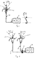
- Fig. 1 shows the operatively simplest application, with one station including one control lever, which is associated to the electronic control and monitoring unit according to this invention.
- the control station 1 has a control device 101 for the user to set the control signal, said control setting device 101 being capable of being displaced relative to a stationary reference, such displacement being related to a value of the control signal.
- This control device is associated to electric, electronic and/or electromechanical means for detecting the displacement of the control device 101 and for generating a control signal that is uniquely correlated with said displacement. These means, which are part of the prior art, are not shown.
- the control signal is transmitted to the electronic control and monitoring unit 4 through signal transmission devices that are coherent with the (electric, electronic, electromechanical) signal type generated by the control signal detection means.
- the generated signal is of the electronic type and is transmitted to the electronic control and monitoring unit, and from the electronic control and monitoring unit to the actuator through a CAN BUS.
- the control signal setting device is a control lever 101 which is capable of being angularly displaced (BETA) relative to a stationary reference, such as the fulcrum about which the lever pivots.
- BETA angularly displaced
- Such pivotal displacement of the lever generates the control signal that acts on the device for delivering fuel and/or fuel-air mixture of/to the engine and/or on a flow meter or control device which has a flow metering or controlling member that can be angularly displaced about a predetermined axis.
- the lever and/or flow meter or control device take a predetermined angular position (ALFA) relative to a stationary reference as a function of the angular position (BETA) of the control lever relative to the corresponding stationary reference, thereby establishing a relationship between the control signal generated by the control lever and the characteristics of the fuel, and/or air-fuel flow delivered to the engine.
- AFA angular position
- BETA angular position
- Figs. 1 to 4 show the different applications of the invention.
- the invention may be implemented as shown in Fig. 1 to a system comprising one control station with one control lever and one actuator.
- the control signal i.e. the angular displacement BETA of the control lever is received by usual electric, electronic or electromechanical systems and is digitized and transmitted to the electronic control and monitoring unit 4, which computes the preset function and provides, as a result of such computation, a control signal which is transferred, still preferably through a CAN bus 3, to the actuator 2, which accordingly actuates the fuel throttle of the engine.
- the displacement of the control lever 101 may provide a nonlinear throttle response.
- a variety of mathematical functions may be stored into a nonvolatile memory associated to said electronic control unit 4, and the setting of the mathematical function or table of correspondence is preferably effected by using DIP switches, not shown, whose various combinations correspond to different mathematical functions and/or tables of correspondence (as shown in Fig. 11) linking ALFA and BETA. Therefore, the user may select beforehand a desired kind of drive by setting the correspondence between ALFA and BETA given by the different functions, which corresponds to a different power response behavior of the engine, hence a different behavior of the watercraft.
- Fig. 2 shows a system according to this invention, which comprises two control stations 1 and 1' having one control lever 101 and 101' and one actuator 2.
- the electronic control and monitoring unit 4 is positioned downstream from the control stations and the control lever displacement signal BETA is transmitted to the electronic control and monitoring 4 through the CAN buses 3.
- the electronic control and monitoring unit processes, as described above, the BETA signal from the control station selected by the user by means of said toggle switch.
- the electronic control and monitoring unit 4 transmits the signal to the actuator 2, still through a CAN bus, as discussed above, and the actuator will open the throttle, by means of a control lever, through an angle ALFA.
- FIG. 2 further shows the POSITIVE BETA displacement of the control lever 101 and the NEGATIVE BETA displacement of the control lever 101'.
- POSITIVE BETA a fore displacement of the control lever
- NEGATIVE BETA a fore displacement of the control lever
- an aft displacement of the control lever i.e. NEGATIVE BETA
- inverter which drives the propeller in reverse rotation, so that the watercraft is pushed backwards due to the reverse rotation of the propeller and to the opening of the throttle.
- f'(BETA) may be programmed and set on the electronic control and monitoring unit 4, exactly like the functions f(BETA), to be used when the displacement of the control lever has a negative value.
- This negative displacement may be associated, thanks to the electronic control and monitoring unit 4 of this invention, to a function f'(BETA) that is different from f(BETA), for instance programmed in such a manner that the reverse maneuver of the watercraft is facilitated, with an enhanced linearity in the first portion of the control lever range and a maximum deliverable power of less than 100%.
- the drive is thus dramatically facilitated as compared with prior art systems, in which the acceleration of the watercraft in reverse motion was essentially equal to forward motion acceleration.
- control lever 101' may be associated to the function f(BETA) used for harbor maneuvers, whereas a different control lever 101 is associated to a function f(BETA) used, for instance, for power saving navigation.
- various stations may be associated either to the same or different functions f(BETA), so that the watercraft may be easily and flexibly driven, to meet different user requirements.
- the electronic control and monitoring unit 4 may be further associated to a control station with two levers 101, 201, like in Fig. 3.
- the electronic control and monitoring unit 4 allows to handle signals from said two control levers and transmits the signal, appropriately processed by f(BETA), to the two actuators, for instance to control two engines.
- Fig. 4 shows a system according to the present invention, which comprises three control stations with two levers and two actuators, in which the operating conditions are highly flexible, and result from the combination of the above described characteristics of the invention.
- control and monitoring electronic units as actuators, with exactly the same operation as discussed above.
- the control stations are typically equipped with a toggle switch, which is controlled by the user to inform the electronic control and monitoring unit about the user selected control station to drive the watercraft.
- the electronic control and monitoring unit which receives the angular control lever displacement signal BETA from the selected control station, processes the signal as described above, and computes the displacement of the throttle controlling actuator lever ALFA by the function f(BETA).
- this may provide a number of different functions f(BETA) associated to the different control levers, particularly a specific control lever may be associated to the function f(BETA) used for harbor maneuvers, whereas a different control station is associated to a function f(BETA) used for power saving navigation, as described above.
- the various stations may be associated either to the same or different functions f(BETA), so that the watercraft may be easily and flexibly driven, to meet different user requirements.
- the electronic control and monitoring unit may be also used for the control signal transmission checking function. This allows to overcome the above mentioned prior art problems associated to a lack of the monitoring capability.
- the electronic control and monitoring unit monitors the communication and, when a wrong signal or a lack of signal is detected in the control station, the electronic control unit brings the throttle controlling lever in the minimum opening condition, and the inverter is brought in the neutral position, while the user receives an error warning by optical and/or acoustic signals.
- the throttle controlling lever remains in the minimum opening condition and the inverter remains in the neutral position until the error is acknowledged by the electronic control and monitoring unit and/or the user possibly selects a different control station.
- the electronic control and monitoring unit stores the sequence of detected errors. As described above, the electronic control and monitoring unit detects any control system operation errors, warns the user thereof, and in some cases takes appropriate danger preventing measures. In a preferred embodiment, the electronic control and monitoring unit also associates a code to each detected error type, and stores the rate of occurrence of the error. Hence, the electronic control and monitoring equipment may monitor any error occurring in the system and the number of occurrences of such error. The electronic control and monitoring unit may also monitor any engine and actuator malfunctions, and once more associate a code to each error and/or malfunction.
- All errors and malfunctions are identified as such by the electronic control and monitoring unit substantially through two preferred arrangements: according to the first arrangement, known sensors are provided to check operation and to transmit a wrong operation signal to the electronic control and monitoring unit whenever an abnormality occurs in the subsystem wherewith they are associated.
- the electronic control and monitoring unit generates an operation history for the control system, the engine and its parts and the actuator, and for any other system or subsystem of the watercraft which is connected to the electronic control and monitoring unit to transmit an operation signal thereto.
- the electronic control and monitoring unit may compare the operation signal it receives from any watercraft subsystem to identify any abnormality, i.e. any signal that excessively differs from the history of identical signals that was previously generated by the above mentioned detection.
- the electronic control and monitoring unit may provide not only a list of the occurrences and types of malfunctions in the control system as such, but also a list of the occurrences and types or errors and malfunctions of the watercraft part under its control. Therefore, the result of said monitoring action by the electronic control and monitoring unit may be advantageously used for maintenance purposes. This result may be displayed and/or printed and/or electronically transmitted to the user or to the watercraft maintenance personnel and/or communicated in any other manner, whereby watercraft maintenance may be well targeted, hence more effective. It will be understood, for instance, that if the electronic control and monitoring unit detects several control signal transmission errors at the remote control station, then the remote control station ought to be first checked out and possibly repaired and/or serviced.
- the electronic control and monitoring unit may be further used for self-checking and for providing both the complete error code and occurrence list and the suggested preventive maintenance.
- a list of errors and occurrences, associated to the recommended preventive maintenance might be entered in the electronic control and monitoring unit.
- the electronic control and monitoring unit checks the history of system and/or subsystem and/or engine and or actuator error and/or malfunction signals and then may be able to generate, by comparison, a preventive maintenance warning, which may be useful for the user and/or the maintenance personnel for maintenance purposes.
- the system of this invention may further provide a feedback to the control and monitoring electronic unit, particularly the engine speed, i.e. the number of revolutions made by the engine may be transmitted as a signal to the control unit which, in a preferred embodiment, may use such number of revolutions to appropriately set the ALFA value and/or to check for any abnormalities or errors in the system.
- the displacement value ALFA may have to correspond to a given engine rpm value and, thanks to such feedback, the electronic control and monitoring unit might check the compliance with this value and the proper transmission of the control signal to the actuator. It may be easily understood for instance that, assuming a 10% throttle opening, the engine rpm cannot and must not be close to the maximum speed.
- the feedback allows to detect this error and to take the precautionary measures described above.
- a signal from the engine and/or the actuator such signal may be used by the electronic control and monitoring unit and/or by the control station to check and/or monitor and/or set the above values of the table of correspondence. Therefore, the operation may be as follows: the user sets a certain engine rpm and selects, through a combination of keys, a control lever displacement corresponding to the set rpm. Therefore, the electronic control and monitoring unit uses the feedback from the engine, i.e. its rpm, which is a function of the angular displacement ALFA, and through the control lever displacement BETA, it creates a table of correspondence as selected by the user.
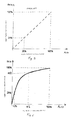
- FIG. 5 This diagram clearly shows the linearity of this relationship and the resulting straight line: for example, an angular displacement BETA of the control lever that is 20% of the maximum displacement corresponds, in prior art, to a 20% displacement of the throttle controlling lever, and to a 20% opening of the throttle.
- an opening of the control lever that mechanically or electromechanically controls the throttle of the watercraft engine corresponds to a throttle opening, that is to a greater fuel flow to the engine. The greater fuel flow causes the engine to increase the number of its operating revolutions per minute and, as a result, its power.
- a control set on a control lever does not cause a proportional 20% increase of the delivered power, which may be higher or lower depending, as mentioned above, on additional parameters, such as the number of revolutions at which the throttle opens.
- the throttle opening and the displacement of the actuator lever that controls it is preferably nonlinear with the control BETA set on the control lever of the control station, so that the power delivered to the engine may be controlled, to such an extent as to make the delivered power linear with the control lever displacement.
- the curve was assumed to be such that a 20% control lever displacement corresponds to a 10% increase of ALFA, therefore of the opening of the throttle controlling lever, and of the throttle itself, equal to 10% of the maximum opening.
- a 85% displacement of BETA corresponds to a 40% ALFA.
- This provides a particularly accurate control in an intermediate throttle opening range, which allows the user to have a considerable control, in such a range, over the throttle opening, which is relatively small when compared with the BETA generating displacement of the control lever.
- the power delivered to the engine may be easily controlled all over the intermediate displacement range of the control lever, thereby allowing the user to have an accordingly accurate control over the power delivered by the engine in that range.
- Fig. 7 shows such an ALFA and BETA relating function that the control set by the control lever corresponds to a displacement ALFA which depends on BETA in accordance with a curve having a convexity and a concavity.
- the nonlinearity of BETA with ALFA is used to obtain a user-customizable drive.
- the electronic control and monitoring unit may be programmed with functions f that are adapted to the different drive styles of users, providing a simple and safe drive for any user.
- Fig. 8 shows such a mathematical dependence, or function, of ALFA on BETA, as to obtain a quasi linearity of the two displacements until a given displacement of the control lever is reached. Above a given BETA value, here shown as 50%, the throttle opening is very fast. This profile may be used, for instance, for coastwise navigation when high-speed navigation capabilities are still required.
- Fig. 9 and Fig. 10 show two situations in which the maximum angular displacement of the control lever corresponds to a small throttle opening, i.e. a 50% opening in Fig. 9 and a 10% opening in Fig. 10. These two functions may be particularly useful for mooring operations or maneuvers in narrow spaces.
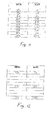
- Fig. 12 shows a table of correspondence in which three main values are only entered and in which the omitted intermediate values are determined by the electronic control and monitoring unit by an interpolation, which may be a linear, a least-squares interpolation or any other type of interpolation, other than the ones mentioned above.
- an interpolation which may be a linear, a least-squares interpolation or any other type of interpolation, other than the ones mentioned above.
- the displacement value is detected by the control electronic unit, which compares it with the value in the table of correspondence. If the BETA value is equal to a previously set value, the corresponding ALFA value is directly read from the table. Conversely, if the BETA value is somewhere between two different set values, without corresponding to none of them, the electronic control and monitoring unit interpolates the value in any manner to provide the interpolated ALFA value.
- the above table of correspondence may be set either into a nonvolatile memory, and selected by using the DIP switches as described above, or directly through special devices in the control station during use. This allows the user the set BETA and ALFA values before, during or after operation, directly from the control station, by selecting a control configuration e.g. adapted to sea conditions, thereby making the inventive device even more flexible.
- the control station may be associated to an input keypad through which said values may be entered.
Applications Claiming Priority (2)
| Application Number | Priority Date | Filing Date | Title |
|---|---|---|---|
| ITSV20030046 | 2003-11-14 | ||
| IT000046A ITSV20030046A1 (it) | 2003-11-14 | 2003-11-14 | Sistema elettromeccanico di comando in particolare per |
Publications (3)
| Publication Number | Publication Date |
|---|---|
| EP1531247A2 true EP1531247A2 (de) | 2005-05-18 |
| EP1531247A3 EP1531247A3 (de) | 2008-06-11 |
| EP1531247B1 EP1531247B1 (de) | 2010-09-01 |
Family
ID=34430805
Family Applications (1)
| Application Number | Title | Priority Date | Filing Date |
|---|---|---|---|
| EP04105033A Expired - Fee Related EP1531247B1 (de) | 2003-11-14 | 2004-10-14 | Elektromechanisches Regelungssystem, insbesondere für maritime Anwendungen |
Country Status (3)
| Country | Link |
|---|---|
| US (1) | US20050143875A1 (de) |
| EP (1) | EP1531247B1 (de) |
| IT (1) | ITSV20030046A1 (de) |
Cited By (1)
| Publication number | Priority date | Publication date | Assignee | Title |
|---|---|---|---|---|
| US9805524B2 (en) | 2016-03-11 | 2017-10-31 | General Electric Company | Systems and methods for displaying a fault analysis instructions of an engine control subsystem |
Families Citing this family (5)
| Publication number | Priority date | Publication date | Assignee | Title |
|---|---|---|---|---|
| US7315779B1 (en) | 2006-12-22 | 2008-01-01 | Bombardier Recreational Products Inc. | Vehicle speed limiter |
| US7380538B1 (en) | 2006-12-22 | 2008-06-03 | Bombardier Recreational Products Inc. | Reverse operation of a vehicle |
| US7530345B1 (en) | 2006-12-22 | 2009-05-12 | Bombardier Recreational Products Inc. | Vehicle cruise control |
| IT1395074B1 (it) * | 2009-08-06 | 2012-09-05 | Ultraflex Spa | Comando monoleva per il controllo combinato della condizione di alimentazione di uno o piu' motori e di un meccanismo invertitore di cambio marcia |
| US8762022B1 (en) * | 2012-08-17 | 2014-06-24 | Brunswick Corporation | Marine propulsion system with efficient engine speed delta |
Citations (4)
| Publication number | Priority date | Publication date | Assignee | Title |
|---|---|---|---|---|
| US4856477A (en) | 1987-07-24 | 1989-08-15 | Nissan Motor Company, Limited | Throttle control system for automotive internal combustion engine with fail-safe mechanism |
| DE4417802A1 (de) | 1993-05-21 | 1994-11-24 | Toyota Motor Co Ltd | Motorleistung-Regeleinrichtung |
| US6298824B1 (en) | 1999-10-21 | 2001-10-09 | Brunswick Corporation | Engine control system using an air and fuel control strategy based on torque demand |
| CA2417380A1 (en) | 2002-02-04 | 2003-08-04 | Honda Giken Kogyo Kabushiki Kaisha | Jet propulsion boat |
Family Cites Families (9)
| Publication number | Priority date | Publication date | Assignee | Title |
|---|---|---|---|---|
| JP3065414B2 (ja) * | 1991-12-25 | 2000-07-17 | 三信工業株式会社 | 船舶推進機の遠隔操作装置 |
| US6431930B1 (en) * | 1998-09-29 | 2002-08-13 | Bombardier Motor Corporation Of America | Electronic control system for boats |
| US6273771B1 (en) * | 2000-03-17 | 2001-08-14 | Brunswick Corporation | Control system for a marine vessel |
| US6587765B1 (en) * | 2001-06-04 | 2003-07-01 | Teleflex Incorporated | Electronic control system for marine vessels |
| JP3967221B2 (ja) * | 2002-07-22 | 2007-08-29 | ヤマハマリン株式会社 | 船舶の推進制御装置 |
| US6704643B1 (en) * | 2002-09-16 | 2004-03-09 | Brunswick Corporation | Adaptive calibration strategy for a manually controlled throttle system |
| JP2004218476A (ja) * | 2003-01-10 | 2004-08-05 | Mitsubishi Electric Corp | 電子制御駆動装置 |
| US6757606B1 (en) * | 2003-06-02 | 2004-06-29 | Brunswick Corporation | Method for controlling the operation of an internal combustion engine |
| US6881106B1 (en) * | 2003-10-27 | 2005-04-19 | Brunswick Corporation | Power fault detection system for a communication bus |
-
2003
- 2003-11-14 IT IT000046A patent/ITSV20030046A1/it unknown
-
2004
- 2004-10-14 EP EP04105033A patent/EP1531247B1/de not_active Expired - Fee Related
- 2004-11-15 US US10/987,216 patent/US20050143875A1/en not_active Abandoned
Patent Citations (4)
| Publication number | Priority date | Publication date | Assignee | Title |
|---|---|---|---|---|
| US4856477A (en) | 1987-07-24 | 1989-08-15 | Nissan Motor Company, Limited | Throttle control system for automotive internal combustion engine with fail-safe mechanism |
| DE4417802A1 (de) | 1993-05-21 | 1994-11-24 | Toyota Motor Co Ltd | Motorleistung-Regeleinrichtung |
| US6298824B1 (en) | 1999-10-21 | 2001-10-09 | Brunswick Corporation | Engine control system using an air and fuel control strategy based on torque demand |
| CA2417380A1 (en) | 2002-02-04 | 2003-08-04 | Honda Giken Kogyo Kabushiki Kaisha | Jet propulsion boat |
Cited By (1)
| Publication number | Priority date | Publication date | Assignee | Title |
|---|---|---|---|---|
| US9805524B2 (en) | 2016-03-11 | 2017-10-31 | General Electric Company | Systems and methods for displaying a fault analysis instructions of an engine control subsystem |
Also Published As
| Publication number | Publication date |
|---|---|
| ITSV20030046A1 (it) | 2005-05-15 |
| US20050143875A1 (en) | 2005-06-30 |
| EP1531247B1 (de) | 2010-09-01 |
| EP1531247A3 (de) | 2008-06-11 |
Similar Documents
| Publication | Publication Date | Title |
|---|---|---|
| US6704643B1 (en) | Adaptive calibration strategy for a manually controlled throttle system | |
| US10507898B1 (en) | Lockout for remote controls on marine vessels | |
| US7442102B2 (en) | Boat | |
| US20190353093A1 (en) | Watercraft and system for operating same | |
| US7559815B2 (en) | Remote control device, remote control device side ECU and watercraft | |
| US20080085640A1 (en) | Sailing control system of boat | |
| US7549901B2 (en) | Outboard motor control system | |
| US8032271B2 (en) | Boat propulsion unit and boat | |
| EP1531247B1 (de) | Elektromechanisches Regelungssystem, insbesondere für maritime Anwendungen | |
| US7860616B2 (en) | Remote control system for a watercraft | |
| US10155578B1 (en) | Method and system for controlling a marine drive during shift sensor fault | |
| US7699673B2 (en) | Controller for boat propulsion system and boat propulsion system | |
| US8712671B2 (en) | Engine RPM control device | |
| JP4403195B2 (ja) | 小型船舶のシフト・潮立て装置 | |
| JP4641312B2 (ja) | 船舶駆動用電子制御装置 | |
| JP2001507780A (ja) | トランスミッションのための制御システムおよびそれに適合されたトランスミッション | |
| US11312461B1 (en) | Boat maneuvering control system for boat and boat maneuvering control method for boat | |
| US9290254B2 (en) | Method and arrangement for controlling a ship propulsion system | |
| KR101091622B1 (ko) | 자동차용 변속기의 레버포지션 통신 방법 및 장치 | |
| JP4454594B2 (ja) | 変速機制御装置 | |
| US4794808A (en) | Transmission control | |
| US11685498B2 (en) | Ship maneuvering system | |
| US9278746B1 (en) | Systems and methods for redundant drive-by-wire control of marine engines | |
| CA2619847C (en) | Outboard motor control system | |
| US20230014852A1 (en) | Multi-layer gear determination system |
Legal Events
| Date | Code | Title | Description |
|---|---|---|---|
| PUAI | Public reference made under article 153(3) epc to a published international application that has entered the european phase |
Free format text: ORIGINAL CODE: 0009012 |
|
| AK | Designated contracting states |
Kind code of ref document: A2 Designated state(s): AT BE BG CH CY CZ DE DK EE ES FI FR GB GR HU IE IT LI LU MC NL PL PT RO SE SI SK TR |
|
| AX | Request for extension of the european patent |
Extension state: AL HR LT LV MK |
|
| RIC1 | Information provided on ipc code assigned before grant |
Ipc: B63H 21/22 20060101ALI20080211BHEP Ipc: F02D 41/24 20060101ALI20080211BHEP Ipc: F02D 11/10 20060101AFI20050318BHEP Ipc: F02D 41/26 20060101ALI20080211BHEP Ipc: F02D 41/22 20060101ALI20080211BHEP |
|
| PUAL | Search report despatched |
Free format text: ORIGINAL CODE: 0009013 |
|
| AK | Designated contracting states |
Kind code of ref document: A3 Designated state(s): AT BE BG CH CY CZ DE DK EE ES FI FR GB GR HU IE IT LI LU MC NL PL PT RO SE SI SK TR |
|
| AX | Request for extension of the european patent |
Extension state: AL HR LT LV MK |
|
| 17P | Request for examination filed |
Effective date: 20080908 |
|
| 17Q | First examination report despatched |
Effective date: 20081010 |
|
| AKX | Designation fees paid |
Designated state(s): FR SE |
|
| REG | Reference to a national code |
Ref country code: DE Ref legal event code: 8566 |
|
| GRAP | Despatch of communication of intention to grant a patent |
Free format text: ORIGINAL CODE: EPIDOSNIGR1 |
|
| GRAS | Grant fee paid |
Free format text: ORIGINAL CODE: EPIDOSNIGR3 |
|
| GRAA | (expected) grant |
Free format text: ORIGINAL CODE: 0009210 |
|
| AK | Designated contracting states |
Kind code of ref document: B1 Designated state(s): FR SE |
|
| REG | Reference to a national code |
Ref country code: SE Ref legal event code: TRGR |
|
| PLBE | No opposition filed within time limit |
Free format text: ORIGINAL CODE: 0009261 |
|
| STAA | Information on the status of an ep patent application or granted ep patent |
Free format text: STATUS: NO OPPOSITION FILED WITHIN TIME LIMIT |
|
| 26N | No opposition filed |
Effective date: 20110606 |
|
| REG | Reference to a national code |
Ref country code: FR Ref legal event code: PLFP Year of fee payment: 12 |
|
| REG | Reference to a national code |
Ref country code: FR Ref legal event code: ST Effective date: 20160630 |
|
| PG25 | Lapsed in a contracting state [announced via postgrant information from national office to epo] |
Ref country code: FR Free format text: LAPSE BECAUSE OF NON-PAYMENT OF DUE FEES Effective date: 20151102 |
|
| REG | Reference to a national code |
Ref country code: FR Ref legal event code: D3 Effective date: 20160816 |
|
| PGRI | Patent reinstated in contracting state [announced from national office to epo] |
Ref country code: FR Effective date: 20160816 |
|
| REG | Reference to a national code |
Ref country code: FR Ref legal event code: PLFP Year of fee payment: 13 |
|
| REG | Reference to a national code |
Ref country code: FR Ref legal event code: PLFP Year of fee payment: 14 |
|
| REG | Reference to a national code |
Ref country code: FR Ref legal event code: PLFP Year of fee payment: 15 |
|
| PGFP | Annual fee paid to national office [announced via postgrant information from national office to epo] |
Ref country code: SE Payment date: 20191024 Year of fee payment: 16 |
|
| PGFP | Annual fee paid to national office [announced via postgrant information from national office to epo] |
Ref country code: FR Payment date: 20191024 Year of fee payment: 16 |
|
| REG | Reference to a national code |
Ref country code: SE Ref legal event code: EUG |
|
| PG25 | Lapsed in a contracting state [announced via postgrant information from national office to epo] |
Ref country code: FR Free format text: LAPSE BECAUSE OF NON-PAYMENT OF DUE FEES Effective date: 20201031 |
|
| PG25 | Lapsed in a contracting state [announced via postgrant information from national office to epo] |
Ref country code: SE Free format text: LAPSE BECAUSE OF NON-PAYMENT OF DUE FEES Effective date: 20201015 |