EP1530937B1 - Aufbewahrungs- und/oder Transporteinrichtung für eine Krawatte oder dergleichen - Google Patents
Aufbewahrungs- und/oder Transporteinrichtung für eine Krawatte oder dergleichen Download PDFInfo
- Publication number
- EP1530937B1 EP1530937B1 EP04025717A EP04025717A EP1530937B1 EP 1530937 B1 EP1530937 B1 EP 1530937B1 EP 04025717 A EP04025717 A EP 04025717A EP 04025717 A EP04025717 A EP 04025717A EP 1530937 B1 EP1530937 B1 EP 1530937B1
- Authority
- EP
- European Patent Office
- Prior art keywords
- necktie
- container
- transporting
- storing
- side wall
- Prior art date
- Legal status (The legal status is an assumption and is not a legal conclusion. Google has not performed a legal analysis and makes no representation as to the accuracy of the status listed.)
- Expired - Lifetime
Links
- 238000004804 winding Methods 0.000 claims description 18
- 239000000463 material Substances 0.000 claims description 3
- 239000004793 Polystyrene Substances 0.000 claims description 2
- NIXOWILDQLNWCW-UHFFFAOYSA-N acrylic acid group Chemical group C(C=C)(=O)O NIXOWILDQLNWCW-UHFFFAOYSA-N 0.000 claims description 2
- XAGFODPZIPBFFR-UHFFFAOYSA-N aluminium Chemical compound [Al] XAGFODPZIPBFFR-UHFFFAOYSA-N 0.000 claims description 2
- 229910052782 aluminium Inorganic materials 0.000 claims description 2
- 239000007769 metal material Substances 0.000 claims description 2
- 229920003023 plastic Polymers 0.000 claims description 2
- 239000004417 polycarbonate Substances 0.000 claims description 2
- 229920000515 polycarbonate Polymers 0.000 claims description 2
- 229920002223 polystyrene Polymers 0.000 claims description 2
- 229910000831 Steel Inorganic materials 0.000 claims 1
- 239000004411 aluminium Substances 0.000 claims 1
- 239000004033 plastic Substances 0.000 claims 1
- 239000010959 steel Substances 0.000 claims 1
- 238000005096 rolling process Methods 0.000 description 2
- 239000012780 transparent material Substances 0.000 description 2
- 230000002411 adverse Effects 0.000 description 1
- 230000006735 deficit Effects 0.000 description 1
- 239000000428 dust Substances 0.000 description 1
- 230000000694 effects Effects 0.000 description 1
- 238000003780 insertion Methods 0.000 description 1
- 230000037431 insertion Effects 0.000 description 1
- 230000002035 prolonged effect Effects 0.000 description 1
- 229910001220 stainless steel Inorganic materials 0.000 description 1
- 239000010935 stainless steel Substances 0.000 description 1
Images

Classifications
-
- A—HUMAN NECESSITIES
- A45—HAND OR TRAVELLING ARTICLES
- A45C—PURSES; LUGGAGE; HAND CARRIED BAGS
- A45C11/00—Receptacles for purposes not provided for in groups A45C1/00-A45C9/00
-
- A—HUMAN NECESSITIES
- A47—FURNITURE; DOMESTIC ARTICLES OR APPLIANCES; COFFEE MILLS; SPICE MILLS; SUCTION CLEANERS IN GENERAL
- A47G—HOUSEHOLD OR TABLE EQUIPMENT
- A47G25/00—Household implements used in connection with wearing apparel; Dress, hat or umbrella holders
- A47G25/78—Necktie-pressing devices, e.g. combined with holding devices
Definitions
- the invention relates to the storage of a tie.
- tie bags or cases For transportation, for example during a trip or the like, tie bags or cases have been developed in which one or a number of ties can be transported folded.
- the object of the invention is to avoid the aforementioned disadvantages and to provide a device for the storage and / or transport of ties, are avoided with the impairments of the tie.
- a storage and / or transport device for a tie with a container having a circumferential side wall and an area enclosed by the side wall bottom concluding bottom and with a container on the top closing, at the upper edge region of the side wall attachable lid, wherein the lid includes a winding mandrel for winding the tie, which extends approximately centrally substantially along the central axis of the container into this and has a slot for receiving a portion of the tie, and wherein the side wall is a slot-shaped, at least according to the tie width formed free area for pulling the tie into the container when winding the tie by twisting the lid and container against each other, and wherein the inner surface of the side wall circumferentially one substantially uniform Distance from the axis of rotation of the winding mandrel and the outer surface of the side wall and / or the lid at circumferentially approximately uniform configuration, at least two substantially planar and at least approximately tangential to the container diameter aligned outer surfaces for an in the horizontal or vertical storage of the container ordered side
- the tie can be kept gently, since it gets no kinks through the tight rolling and is protected by the container against adverse effects from the outside, including dust and dirt.
- the side wall of the container and / or the cover may be provided with four, eight or sixteen substantially planar outer surface areas, so that an arrangement of a plurality of containers in columns and rows may be provided.
- At least one storage and / or transport device may have at least one connection device for attachment to another storage and / or transport device, in order thus to allow a permanently aligned arrangement of a plurality of storage and / or transport devices.
- the connecting device can be detachably or permanently provided on the cover and / or the container and be designed for a detachable or permanent attachment.
- the storage and / or transport means may be limited in terms of their dimensions either to a particular type of tie, e.g. B. a narrow tie made of a thin material or a wide tie made of a thick material. But it is also a training universal type for a variety of tie types possible. It can also be the slot in the Winding mandrel of the container and / or the slot-shaped free area in the side wall of the container have a corresponding design.
- the container may have at least in a portion of its side wall a view of the inner side tie arranged configuration, so that even without opening the storage and / or transport device or even at least partial removal of the tie the tie pattern is recognizable and thus targeted a selection the desired tie is possible.
- the container and / or the lid at least partially made of a particular transparent plastic formed, such.
- a particular transparent plastic formed such as polystyrene, polycarbonate or acrylic, and / or it may be the container and / or the lid at least partially made of a metallic material, such.
- a metallic material such as stainless steel or aluminum, so that in addition to a particularly high-quality look and pleasant feel and a very high stability and thus insensitivity to external influences is given.
- the container consists of a non-transparent material, at least one viewing window can be formed as a recess, which is preferably closed with a transparent material.
- the slot of the winding mandrel for receiving the portion of the tie can be open on one side, so that the threading of the portion of the tie to be performed is particularly easy and simple.
- the open end of the slot may be provided with a projecting portion, so that accidental slipping out of the performed portion of the tie as a function of slot thickness and tie thickness prevented or at least inhibited.
- At least one connecting device for fastening the storage and / or transport device may be provided on at least one further storage and / or transport device, the z. B. form or force or can be designed as a magnetic or Velcro.
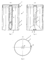
- Fig. 1 shows a perspective view of a storage and / or transport device 1 for a tie, not shown in the drawing.
- the storage and / or transport device 1 in this case has a container 2, which includes a circumferential side wall 3 and a lower-side bottom 4 and an area enclosed thereby 5 for the arrangement of the tie.
- the container 2 is closed on the upper side with a cover 7 which can be attached to the upper edge region 6 of the side wall 3, wherein the cover 7 contains a winding mandrel 8 for winding the tie.
- the mandrel 8 extends approximately centrally substantially along the central axis of the container 2 in this in and has a slot 9 through which a portion of the tie can be passed for winding.
- the side wall 3 is provided with a slot-shaped, at least corresponding to the tie width width formed free area 10 for pulling the tie into the container 2.
- the narrow middle region of a tie is inserted into the slot 9 for winding the tie, with a projecting portion 11 at the open end of the slot 9 prevents slipping out of the tie. Then, the winding mandrel 8 is introduced into the region 5 of the container 2, wherein the remaining part of the tie remains due to lateral introduction into the open area 10 outside the container 2.
- the mandrel 8 is provided on the underside with a guide projection 12 which engages in a correspondingly recessed configuration 13 of the bottom 4, when the cover 7 is arranged on the upper side on the edge region 6 of the container 2 and in particular held securely by latching projections there. By turning lid 7 and container 2 against each other, the tie can then be wound up and drawn into the container 2.
- the inner surface of the side wall 3 has circumferentially a substantially uniform distance from the axis of rotation of the winding mandrel 8 and is therefore at least approximately round.
- the outer surface of the side wall 3 and / or the lid 7 may each have at circumferentially approximately uniform configuration at least two substantially planar and at least approximately tangential to the container diameter aligned outer surfaces, so that a horizontal container can not roll and a variety of standing containers arranged side by side can be stored.
- the number of outer surfaces may preferably be even.
Landscapes
- Details Of Rigid Or Semi-Rigid Containers (AREA)
- Packages (AREA)
- Packaging Of Annular Or Rod-Shaped Articles, Wearing Apparel, Cassettes, Or The Like (AREA)
- Holders For Apparel And Elements Relating To Apparel (AREA)
- Refuse Collection And Transfer (AREA)
- Lubricants (AREA)
Description
- Die Erfindung betrifft die Aufbewahrung einer Krawatte.
- Aus der Praxis sind verschiedenste Möglichkeiten bekannt, eine Krawatte während der Nichtbenutzung aufzubewahren. Neben der liegenden Aufbewahrung im gefalteten Zustand existieren spezielle Krawattenhalter, die eine Vielzahl von Streben oder dergleichen für die hängende Aufbewahrung mehrerer Krawatten aufweisen. Auch haben Schubladen- oder Regalsysteme Verbreitung gefunden, die quader- oder wabenförmigen Fächer für die Aufbewahrung von aufgerollten Krawatten beinhalten. EP 799 591 A offenbart einen Aufbewahrungsbehälter für eine aufgerollte Krawatte.
- Für den Transport, beispielsweise bei einer Reise oder dergleichen, sind Krawattentaschen oder -etuis entwickelt worden, in denen eine oder eine Anzahl Krawatten gefaltet transportiert werden kann.
- Nachteilig hierbei ist, dass die vorgenannten Aufbewahrungsmöglichkeiten keinen schonenden Umgang garantieren und es, z. B. bei gefalteter Aufbewahrung, zu Knickstellen kommen kann, die unschön sind und erst nach längerem Tragen wieder verschwinden. Auch die aufgerollte Aufbewahrung in Schubladen oder Regalfächern ist nicht ideal, da die Fächer aus Handhabungsgründen relativ groß ausgebildet sein müssen. Zudem ist das Aufrollen von Hand schwierig und bringt keine gleichmäßigen Ergebnisse, so dass es auch hier zu unschönen Knickstellen kommen kann.
- Aufgabe der Erfindung ist es, die vorgenannten Nachteile zu vermeiden und eine Einrichtung für die Aufbewahrung und/oder den Transport von Krawatten anzugeben, mit der Beeinträchtigungen der Krawatte vermieden werden.
- Diese Aufgabe wird gelöst durch eine Aufbewahrungs- und/oder Transporteinrichtung für eine Krawatte, mit einem Behälter, der eine umlaufende Seitenwandung und einen den von der Seitenwandung umschlossenen Bereich unterseitig abschließenden Boden aufweist und mit einem den Behälter oberseitig verschließenden, an dem oberen Randbereich der Seitenwandung anbringbaren Deckel, wobei der Deckel einen Wickeldorn zum Aufwickeln der Krawatte beinhaltet, der sich in etwa mittig im Wesentlichen entlang der Mittelachse des Behälters in diesen hinein erstreckt und einen Schlitz zur hindurchgeführten Aufnahme eines Teilbereichs der Krawatte aufweist, und wobei die Seitenwandung einen schlitzförmigen, zumindest entsprechend der Krawattenbreite ausgebildeten Freibereich zum Einziehen der Krawatte in den Behälter beim Aufwickeln der Krawatte durch Verdrehen von Deckel und Behälter gegeneinander aufweist, und wobei die Innenfläche der Seitenwandung umlaufend einen im Wesentlichen einheitlichen Abstand zur Drehachse des Wickeldorns aufweist und die Außenfläche der Seitenwandung und/oder des Deckels bei umlaufend in etwa gleichmäßiger Ausgestaltung zumindest zwei im Wesentlichen ebene und zumindest annähernd tangential zum Behälterdurchmesser ausgerichtete Außenflächen für ein bei der liegenden oder stehenden Aufbewahrung der Behälter geordnetes Nebeneinander mehrerer Behälter aufweist.
- Hierdurch kann die Krawatte schonend aufgewahrt werden, da sie durch das straffe Aufrollen keine Knickstellen bekommt und durch den Behälter vor Beeinträchtigungen von außen, einschließlich Verstauben und Verschmutzen, geschützt ist.
- Aufgrund der Behälterform mit den tangentialen Außenflächen ist bei der liegenden oder stehenden Aufbewahrung der Behälter in einer Schublade oder einem Regal ein geordnetes Nebeneinander mehrerer Behälter problemlos möglich. Die Seitenwandung des Behälters und/oder des Deckels kann insofern mit vier, acht oder sechzehn im Wesentlichen ebenen Außenflächenbereichen versehen sein, so dass eine Anordnung mehrerer Behälter in Spalten und Reihen vorgesehen sein kann.
- Auch kann wenigstens eine Aufbewahrungs- und/oder Transporteinrichtung zumindest eine Verbindungseinrichtung zur Befestigung an einer anderen Aufbewahrungs- und/oder Transporteinrichtung aufweisen, um somit eine dauerhaft ausgerichtete Anordnung mehrerer Aufbewahrungs- und/oder Transporteinrichtungen zu ermöglichen.
- Die Verbindungseinrichtung kann dabei an dem Deckel und/oder dem Behälter lösbar oder dauerhaft vorgesehen sein und für eine lösbare oder dauerhafte Befestigung ausgebildet sein.
- Vorzugsweise kann die Aufbewahrungs- und/oder Transporteinrichtung in Bezug auf ihre Abmessungen entweder auf einen bestimmten Krawattentyp, z. B. eine schmale Krawatte aus einem dünnen Material oder aber eine breite Krawatte aus einem dicken Material abgestimmt sein. Es ist aber auch eine Ausbildung universeller Art für verschiedenste Krawattentypen möglich. Dabei kann auch der Schlitz in dem Wickeldorn des Behälters und/oder der schlitzförmige Freibereich in der Seitenwandung des Behälters eine entsprechende Ausbildung aufweisen.
- Vorzugsweise kann der Behälter zumindest in einem Teilbereich seiner Seitenwandung eine die Sicht auf die innenseitig angeordnete Krawatte erlaubende Ausgestaltung aufweisen, so dass auch ohne Öffnen der Aufbewahrungs- und/oder Transporteinrichtung oder gar zumindest teilweises Entfernen der Krawatte das Krawattendessin erkennbar ist und somit gezielt eine Auswahl der gewünschten Krawatte möglich ist.
- Erfindungsgemäß kann der Behälter und/oder der Deckel zumindest teilweise aus einem insbesondere transparent ausgebildeten Kunststoff, wie z. B. Polystyrol, Polycarbonat oder Acryl, bestehen und/oder es kann der Behälter und/oder der Deckel zumindest teilweise aus einem metallischen Werkstoff, wie z. B. Edelstahl oder Aluminium, bestehen, so dass neben einer besonders hochwertigen Optik und angenehmen Haptik auch eine sehr hohe Stabilität und somit eine Unempfindlichkeit gegen äußere Einwirkungen gegeben ist. Sofern der Behälter aus einem nicht transparenten Material besteht, kann wenigstens ein Sichtfenster als Aussparung, die vorzugsweise mit einem transparenten Material verschlossen ist, ausgebildet sein.
- Vorteilhafterweise kann der Schlitz des Wickeldorns für die Aufnahme des Teilbereichs der Krawatte einseitig offen ausgebildet sein, so dass das Einfädeln des durchzuführenden Teilbereichs der Krawatte besonders leicht und einfach möglich ist.
- Dabei kann das offene Ende des Schlitzes mit einem vorspringenden Bereich versehen sein, so dass ein versehentliches Herausrutschen des durchgeführten Teilbereichs der Krawatte in Abhängigkeit von Schlitzstärke und Krawattendicke verhindert oder aber zumindest gehemmt wird.
- Vorzugsweise kann zumindest eine Verbindungseinrichtung zur Befestigung der Aufbewahrungs- und/oder Transporteinrichtung an zumindest einer weiteren Aufbewahrungs- und/oder Transporteinrichtung vorgesehen sein, die z. B. form- oder kraftschlüssig oder als Magnet- oder Klettverschluss ausgebildet sein kann.
- Insbesondere ist auch eine vorteilhafterweise schwalbenschwanzförmige Nut-Feder-Verbindung möglich.
- Im Folgenden wird ein in der Zeichnung dargestelltes Ausführungsbeispiel der Erfindung erläutert. Es zeigen:
- Fig. 1
- eine perspektivische Ansicht schräg von oben eines Ausführungsbeispieles einer erfindungsgemäßen Aufbewahrungs- und/oder Transporteinrichtung
- Fig. 2
- eine Schnittdarstellung X-X des Gegenstandes nach Fig. 1,
- Fig. 3
- eine Schnittdarstellung Y-Y des Gegenstandes nach Fig. 1 und
- Fig. 4
- eine Schnittdarstellung Z-Z des Gegenstandes nach Fig. 1.
- In allen Figuren werden für gleiche bzw. gleichartige Bauteile übereinstimmende Bezugszeichen verwendet.
- Fig. 1 zeigt in perspektivischer Darstellung eine Aufbewahrungs- und/oder Transporteinrichtung 1 für eine in der Zeichnung nicht dargestellte Krawatte. Die Aufbewahrungs- und/oder Transporteinrichtung 1 weist dabei einen Behälter 2 auf, der eine umlaufende Seitenwandung 3 und einen unterseitigen Boden 4 sowie einen hierdurch umschlossenen Bereich 5 für die Anordnung der Krawatte beinhaltet.
- Der Behälter 2 ist oberseitig mit einem an dem oberen Randbereich 6 der Seitenwandung 3 anbringbaren Deckel 7 verschließbar, wobei der Deckel 7 einen Wickeldorn 8 zum Aufwickeln der Krawatte beinhaltet.
- Der Wickeldorn 8 erstreckt sich dabei in etwa mittig im Wesentlichen entlang der Mittelachse des Behälters 2 in diesen hinein und weist einen Schlitz 9 auf, durch den ein Teilbereich der Krawatte zum Aufwickeln hindurchgeführt werden kann. Die Seitenwandung 3 ist mit einem schlitzförmigen, zumindest entsprechend der Krawattenbreite ausgebildeten Freibereich 10 zum Einziehen der Krawatte in den Behälter 2 versehen.
- Wie sich anhand der Figuren 2 bis 4 leicht nachvollziehen lässt, wird zum Aufwickeln der Krawatte der schmale mittlere Bereich einer Krawatte in den Schlitz 9 eingeführt, wobei ein vorspringender Bereich 11 am offenen Ende des Schlitzes 9 ein Herausrutschen der Krawatte verhindert. Sodann wird der Wickeldorn 8 in den Bereich 5 des Behälters 2 eingeführt, wobei der restliche Teil der Krawatte aufgrund seitlichen Einführens in den Freibereich 10 außerhalb des Behälters 2 verbleibt.
- Der Wickeldorn 8 ist unterseitig mit einem Führungsvorsprung 12 versehen, der in eine entsprechend vertiefte Ausgestaltung 13 des Bodens 4 eingreift, wenn der Deckel 7 oberseitig auf dem Randbereich 6 des Behälters 2 angeordnet und insbesondere durch Rastvorsprünge dort sicher gehalten ist. Durch Verdrehen von Deckel 7 und Behälter 2 gegeneinander kann die Krawatte dann aufgewickelt und in den Behälter 2 eingezogen werden.
- Die Innenfläche der Seitenwandung 3 weist umlaufend einen im Wesentlichen einheitlichen Abstand zur Drehachse des Wickeldorns 8 auf und ist somit zumindest in etwa rund ausgebildet.
- Die Außenfläche der Seitenwandung 3 und/oder des Deckels 7 kann jeweils bei umlaufend in etwa gleichmäßiger Ausgestaltung zumindest zwei im Wesentlichen ebene und zumindest annähernd tangential zum Behälterdurchmesser ausgerichtete Außenflächen aufweisen, so dass ein liegender Behälter nicht wegrollen kann und auch eine Vielzahl stehender Behälter geordnet nebeneinander aufbewahrt werden können. Die Anzahl der Außenflächen kann dabei vorzugsweise geradzahlig ausgebildet sein.
- Wie sich insbesondere aus Fig. 4 erkennen lässt, sind die Kanten der Seitenwandung 3, die den Freibereich 10 seitlich begrenzen, jeweils einwärts abgewinkelt und sorgfältig entgratet, um ein leichtes Einziehen der Krawatte zu ermöglichen und Beschädigungen der Krawatte zu verhindern. Sofern ein Aufwickeln der Krawatte in beide Richtungen möglich sein soll, z. B. um eine einfache Handhabung und eine Eignung sowohl für Links- als auch für Rechtshänder zu gewährleisten, können wie darstellt beide Kantenbereiche identisch ausgebildet sein.
- Es sind aber auch Ausgestaltungen möglich, bei denen ein Kantenbereich in der bevorzugten Wickelrichtung deutlich stärker einwärts gerichtet ist.
Claims (8)
- Aufbewahrungs- und/oder Transporteinrichtung (1) für eine Krawatte, mit einem Behälter (2), der eine umlaufende Seitenwandung (3) und einen den von der Seitenwandung (3) umschlossenen Bereich (5) unterseitig abschließenden Boden (4) aufweist und mit einem den Behälter (2) oberseitig verschließenden, an dem oberen Randbereich (6) der Seitenwandung (3) anbringbaren Deckel (7), wobei der Deckel (7) einen Wickeldorn (8) zum Aufwickeln der Krawatte beinhaltet, der sich in etwa mittig im Wesentlichen entlang der Mittelachse des Behälters (2) in diesen hinein erstreckt und einen Schlitz (9) zur hindurchgeführten Aufnahme eines Teilbereichs der Krawatte aufweist, und wobei die Seitenwandung (3) einen schlitzförmigen, zumindest entsprechend der Krawattenbreite ausgebildeten Freibereich (10) zum Einziehen der Krawatte in den Behälter (2) beim Aufwickeln der Krawatte durch Verdrehen von Deckel (7) und Behälter (2) gegeneinander aufweist, und wobei die Innenfläche der Seitenwandung (3) umlaufend einen im Wesentlichen einheitlichen Abstand zur Drehachse des Wickeldorns (8) aufweist und die Außenfläche der Seitenwandung (3) und/oder des Deckels (7) bei umlaufend in etwa gleichmäßiger Ausgestaltung zumindest zwei im Wesentlichen ebene und zumindest annähernd tangential zum Behälterdurchmesser ausgerichtete Außenflächen für ein bei der liegenden oder stehenden Aufbewahrung der Behälter geordnetes Nebeneinander mehrerer Behälter aufweist.
- Aufbewahrungs- und/oder Transporteinrichtung (1) nach Anspruch 1, dadurch gekennzeichnet, dass der Behälter (2) zumindest in einem Teilbereich seiner Seitenwandung (3) eine die Sicht auf die innenseitig angeordnete Krawatte erlaubende Ausgestaltung aufweist.
- Aufbewahrungs- und/oder Transporteinrichtung (1) nach Anspruch 1 oder 2, dadurch gekennzeichnet, dass der Behälter (2) und/oder der Deckel (7) zumindest teilweise aus einem insbesondere transparent ausgebildeten Kunststoff, wie z. B. Polystyrol, Polycarbonat oder Acryl, besteht.
- Aufbewahrungs- und/oder Transporteinrichtung (1) nach Anspruch 1 oder 2, dadurch gekennzeichnet, dass der Behälter (2) und/oder der Deckel (7) zumindest teilweise aus einem anderen metallischen Werkstoff, wie z. B. Edelstahl oder Aluminium, besteht.
- Aufbewahrungs- und/oder Transporteinrichtung (1) nach einem der Ansprüche 1 bis 4, dadurch gekennzeichnet, dass die Seitenwandung (3) mit vier, acht oder sechzehn im Wesentlichen ebenen Außenflächenbereiche versehen ist.
- Aufbewahrungs- und/oder Transporteinrichtung (1) nach einem der Ansprüche 1 bis 5, dadurch gekennzeichnet, dass der Schlitz (9) für die Aufnahme des Teilbereichs der Krawatte einseitig offen ausgebildet ist.
- Aufbewahrungs- und/oder Transporteinrichtung (1) nach Anspruch 6, dadurch gekennzeichnet, dass das offene Ende des Schlitzes (9) mit einem vorspringenden Bereich (11) versehen ist.
- Aufbewahrungs- und/oder Transporteinrichtung (1) nach einem der Ansprüche 1 bis 7, dadurch gekennzeichnet, dass zumindest eine Verbindungseinrichtung zur Befestigung an einer anderen Aufbewahrungs- und/oder Transporteinrichtung vorgesehen ist.
Applications Claiming Priority (2)
| Application Number | Priority Date | Filing Date | Title |
|---|---|---|---|
| DE20317762U | 2003-11-17 | ||
| DE20317762U DE20317762U1 (de) | 2003-11-17 | 2003-11-17 | Aufbewahrungs- und/oder Transporteinrichtung für eine Krawatte o.dgl. |
Publications (2)
| Publication Number | Publication Date |
|---|---|
| EP1530937A1 EP1530937A1 (de) | 2005-05-18 |
| EP1530937B1 true EP1530937B1 (de) | 2007-05-02 |
Family
ID=32892530
Family Applications (1)
| Application Number | Title | Priority Date | Filing Date |
|---|---|---|---|
| EP04025717A Expired - Lifetime EP1530937B1 (de) | 2003-11-17 | 2004-10-29 | Aufbewahrungs- und/oder Transporteinrichtung für eine Krawatte oder dergleichen |
Country Status (3)
| Country | Link |
|---|---|
| EP (1) | EP1530937B1 (de) |
| AT (1) | ATE361015T1 (de) |
| DE (2) | DE20317762U1 (de) |
Families Citing this family (1)
| Publication number | Priority date | Publication date | Assignee | Title |
|---|---|---|---|---|
| DE202016101076U1 (de) * | 2016-02-29 | 2017-05-31 | Stefan Denk | Dose zur Einlage von Krawatten |
Family Cites Families (4)
| Publication number | Priority date | Publication date | Assignee | Title |
|---|---|---|---|---|
| US1878400A (en) * | 1931-12-17 | 1932-09-20 | Irschik Joseph | Tie press |
| GB394348A (en) * | 1931-12-21 | 1933-06-21 | Henry Stace May | Improvements in and relating to devices for removing creases from neck-ties and the like and for storing and preserving them |
| EP0799591A1 (de) * | 1996-04-04 | 1997-10-08 | Ikemoto Brush Industry Co., Ltd. | Behälter zum Aufbewahren eines bandförmigen persönlichen Verzierungsgegenstandes |
| US5915547A (en) * | 1997-09-17 | 1999-06-29 | Chen; Chun-Hung | Necktie positioning box structure with stacking feature |
-
2003
- 2003-11-17 DE DE20317762U patent/DE20317762U1/de not_active Expired - Lifetime
-
2004
- 2004-10-29 DE DE502004003668T patent/DE502004003668D1/de not_active Expired - Lifetime
- 2004-10-29 EP EP04025717A patent/EP1530937B1/de not_active Expired - Lifetime
- 2004-10-29 AT AT04025717T patent/ATE361015T1/de not_active IP Right Cessation
Also Published As
| Publication number | Publication date |
|---|---|
| ATE361015T1 (de) | 2007-05-15 |
| EP1530937A1 (de) | 2005-05-18 |
| DE502004003668D1 (de) | 2007-06-14 |
| DE20317762U1 (de) | 2004-08-19 |
Similar Documents
| Publication | Publication Date | Title |
|---|---|---|
| CH684992A5 (de) | Vorrichtung zur Ablage von Compact-Discs. | |
| WO2003029735A1 (de) | Abstellfach für eine kühlgerätetür | |
| DE29707656U1 (de) | Behältnis | |
| EP1530937B1 (de) | Aufbewahrungs- und/oder Transporteinrichtung für eine Krawatte oder dergleichen | |
| DE10257649A1 (de) | Absteller für ein Kältegerät | |
| DE29713629U1 (de) | Ablagerost für Kühlschränke | |
| DE4109153C2 (de) | Vorrichtung zur Aufbewahrung von CD-Kassetten | |
| DE8900997U1 (de) | Regal mit Seitenwänden aus mehrlagigem Faltmaterial | |
| DE8807102U1 (de) | Kantenschutz-Eckwinkel | |
| DE9408580U1 (de) | Bausatz zur Bildung einer Roll- und/oder Stapelbox | |
| EP4470435B1 (de) | Vorrichtung zum halten zumindest eines behältnisses für ein flüssiges körperreinigungsprodukt | |
| DE19646884C2 (de) | Mehrweg-Transportpackung für technische Geräte | |
| CH437457A (de) | Tragvorrichtung insbesondere für Kabel | |
| DE29717578U1 (de) | Halterung für stapelbare Gegenstände | |
| DE29608833U1 (de) | Ablagesystem zur Ablage von Gegenständen | |
| EP4183296A1 (de) | Vorrichtung zur lagerung und/oder zur präsentation, verwendung und verfahren | |
| DE9420714U1 (de) | Versandbehälter für Zeitungen, Zeitschriften o.dgl. | |
| DE29510946U1 (de) | Vorrichtung zur Aufbewahrung und/oder Präsentation von CD-Behältern aus Blech, insbesondere aus Stahlblech | |
| DE3146993A1 (de) | Flachbehaelter zur aufnahme von medizinischen instrumenten | |
| DE9108443U1 (de) | Kantenschutzleiste für Palettenverpackungen | |
| DE29504208U1 (de) | Behälter zur Aufbewahrung von Gegenständen | |
| DE8623415U1 (de) | Fachboden | |
| DE9200379U1 (de) | Konusbefestigung für Möbelflächen | |
| DE9301291U1 (de) | Querteiler für Schubladen, insbesondere zur Aufbewahrung von Arzneimitteln in Apotheken | |
| DE9013109U1 (de) | Flaschenkasten |
Legal Events
| Date | Code | Title | Description |
|---|---|---|---|
| PUAI | Public reference made under article 153(3) epc to a published international application that has entered the european phase |
Free format text: ORIGINAL CODE: 0009012 |
|
| AK | Designated contracting states |
Kind code of ref document: A1 Designated state(s): AT BE BG CH CY CZ DE DK EE ES FI FR GB GR HU IE IT LI LU MC NL PL PT RO SE SI SK TR |
|
| AX | Request for extension of the european patent |
Extension state: AL HR LT LV MK |
|
| 17P | Request for examination filed |
Effective date: 20050810 |
|
| AKX | Designation fees paid |
Designated state(s): AT BE BG CH CY CZ DE DK EE ES FI FR GB GR HU IE IT LI LU MC NL PL PT RO SE SI SK TR |
|
| GRAP | Despatch of communication of intention to grant a patent |
Free format text: ORIGINAL CODE: EPIDOSNIGR1 |
|
| GRAS | Grant fee paid |
Free format text: ORIGINAL CODE: EPIDOSNIGR3 |
|
| GRAA | (expected) grant |
Free format text: ORIGINAL CODE: 0009210 |
|
| AK | Designated contracting states |
Kind code of ref document: B1 Designated state(s): AT BE BG CH CY CZ DE DK EE ES FI FR GB GR HU IE IT LI LU MC NL PL PT RO SE SI SK TR |
|
| PG25 | Lapsed in a contracting state [announced via postgrant information from national office to epo] |
Ref country code: FI Free format text: LAPSE BECAUSE OF FAILURE TO SUBMIT A TRANSLATION OF THE DESCRIPTION OR TO PAY THE FEE WITHIN THE PRESCRIBED TIME-LIMIT Effective date: 20070502 |
|
| REG | Reference to a national code |
Ref country code: GB Ref legal event code: FG4D Free format text: NOT ENGLISH |
|
| REG | Reference to a national code |
Ref country code: CH Ref legal event code: EP |
|
| REG | Reference to a national code |
Ref country code: IE Ref legal event code: FG4D Free format text: LANGUAGE OF EP DOCUMENT: GERMAN |
|
| REF | Corresponds to: |
Ref document number: 502004003668 Country of ref document: DE Date of ref document: 20070614 Kind code of ref document: P |
|
| PG25 | Lapsed in a contracting state [announced via postgrant information from national office to epo] |
Ref country code: SE Free format text: LAPSE BECAUSE OF FAILURE TO SUBMIT A TRANSLATION OF THE DESCRIPTION OR TO PAY THE FEE WITHIN THE PRESCRIBED TIME-LIMIT Effective date: 20070802 |
|
| PG25 | Lapsed in a contracting state [announced via postgrant information from national office to epo] |
Ref country code: ES Free format text: LAPSE BECAUSE OF FAILURE TO SUBMIT A TRANSLATION OF THE DESCRIPTION OR TO PAY THE FEE WITHIN THE PRESCRIBED TIME-LIMIT Effective date: 20070813 |
|
| NLV1 | Nl: lapsed or annulled due to failure to fulfill the requirements of art. 29p and 29m of the patents act | ||
| PG25 | Lapsed in a contracting state [announced via postgrant information from national office to epo] |
Ref country code: PL Free format text: LAPSE BECAUSE OF FAILURE TO SUBMIT A TRANSLATION OF THE DESCRIPTION OR TO PAY THE FEE WITHIN THE PRESCRIBED TIME-LIMIT Effective date: 20070502 |
|
| GBV | Gb: ep patent (uk) treated as always having been void in accordance with gb section 77(7)/1977 [no translation filed] |
Effective date: 20070502 |
|
| REG | Reference to a national code |
Ref country code: IE Ref legal event code: FD4D |
|
| EN | Fr: translation not filed | ||
| PG25 | Lapsed in a contracting state [announced via postgrant information from national office to epo] |
Ref country code: CZ Free format text: LAPSE BECAUSE OF FAILURE TO SUBMIT A TRANSLATION OF THE DESCRIPTION OR TO PAY THE FEE WITHIN THE PRESCRIBED TIME-LIMIT Effective date: 20070502 Ref country code: DK Free format text: LAPSE BECAUSE OF FAILURE TO SUBMIT A TRANSLATION OF THE DESCRIPTION OR TO PAY THE FEE WITHIN THE PRESCRIBED TIME-LIMIT Effective date: 20070502 Ref country code: BG Free format text: LAPSE BECAUSE OF FAILURE TO SUBMIT A TRANSLATION OF THE DESCRIPTION OR TO PAY THE FEE WITHIN THE PRESCRIBED TIME-LIMIT Effective date: 20070802 Ref country code: SI Free format text: LAPSE BECAUSE OF FAILURE TO SUBMIT A TRANSLATION OF THE DESCRIPTION OR TO PAY THE FEE WITHIN THE PRESCRIBED TIME-LIMIT Effective date: 20070502 Ref country code: NL Free format text: LAPSE BECAUSE OF FAILURE TO SUBMIT A TRANSLATION OF THE DESCRIPTION OR TO PAY THE FEE WITHIN THE PRESCRIBED TIME-LIMIT Effective date: 20070502 Ref country code: IE Free format text: LAPSE BECAUSE OF FAILURE TO SUBMIT A TRANSLATION OF THE DESCRIPTION OR TO PAY THE FEE WITHIN THE PRESCRIBED TIME-LIMIT Effective date: 20070502 Ref country code: PT Free format text: LAPSE BECAUSE OF FAILURE TO SUBMIT A TRANSLATION OF THE DESCRIPTION OR TO PAY THE FEE WITHIN THE PRESCRIBED TIME-LIMIT Effective date: 20071002 |
|
| PGFP | Annual fee paid to national office [announced via postgrant information from national office to epo] |
Ref country code: LU Payment date: 20071023 Year of fee payment: 4 Ref country code: MC Payment date: 20071018 Year of fee payment: 4 |
|
| PG25 | Lapsed in a contracting state [announced via postgrant information from national office to epo] |
Ref country code: SK Free format text: LAPSE BECAUSE OF FAILURE TO SUBMIT A TRANSLATION OF THE DESCRIPTION OR TO PAY THE FEE WITHIN THE PRESCRIBED TIME-LIMIT Effective date: 20070502 |
|
| PGFP | Annual fee paid to national office [announced via postgrant information from national office to epo] |
Ref country code: AT Payment date: 20071024 Year of fee payment: 4 |
|
| PLBE | No opposition filed within time limit |
Free format text: ORIGINAL CODE: 0009261 |
|
| STAA | Information on the status of an ep patent application or granted ep patent |
Free format text: STATUS: NO OPPOSITION FILED WITHIN TIME LIMIT |
|
| 26N | No opposition filed |
Effective date: 20080205 |
|
| BERE | Be: lapsed |
Owner name: VAN BERCK, JORG Effective date: 20071031 Owner name: VLASSIS, MICHAEL Effective date: 20071031 |
|
| PG25 | Lapsed in a contracting state [announced via postgrant information from national office to epo] |
Ref country code: IT Free format text: LAPSE BECAUSE OF FAILURE TO SUBMIT A TRANSLATION OF THE DESCRIPTION OR TO PAY THE FEE WITHIN THE PRESCRIBED TIME-LIMIT Effective date: 20070502 Ref country code: GB Free format text: LAPSE BECAUSE OF FAILURE TO SUBMIT A TRANSLATION OF THE DESCRIPTION OR TO PAY THE FEE WITHIN THE PRESCRIBED TIME-LIMIT Effective date: 20070502 Ref country code: GR Free format text: LAPSE BECAUSE OF FAILURE TO SUBMIT A TRANSLATION OF THE DESCRIPTION OR TO PAY THE FEE WITHIN THE PRESCRIBED TIME-LIMIT Effective date: 20070803 Ref country code: FR Free format text: LAPSE BECAUSE OF FAILURE TO SUBMIT A TRANSLATION OF THE DESCRIPTION OR TO PAY THE FEE WITHIN THE PRESCRIBED TIME-LIMIT Effective date: 20071228 |
|
| PG25 | Lapsed in a contracting state [announced via postgrant information from national office to epo] |
Ref country code: RO Free format text: LAPSE BECAUSE OF FAILURE TO SUBMIT A TRANSLATION OF THE DESCRIPTION OR TO PAY THE FEE WITHIN THE PRESCRIBED TIME-LIMIT Effective date: 20070502 |
|
| PG25 | Lapsed in a contracting state [announced via postgrant information from national office to epo] |
Ref country code: BE Free format text: LAPSE BECAUSE OF NON-PAYMENT OF DUE FEES Effective date: 20071031 |
|
| PG25 | Lapsed in a contracting state [announced via postgrant information from national office to epo] |
Ref country code: FR Free format text: LAPSE BECAUSE OF FAILURE TO SUBMIT A TRANSLATION OF THE DESCRIPTION OR TO PAY THE FEE WITHIN THE PRESCRIBED TIME-LIMIT Effective date: 20070502 |
|
| PG25 | Lapsed in a contracting state [announced via postgrant information from national office to epo] |
Ref country code: EE Free format text: LAPSE BECAUSE OF FAILURE TO SUBMIT A TRANSLATION OF THE DESCRIPTION OR TO PAY THE FEE WITHIN THE PRESCRIBED TIME-LIMIT Effective date: 20070502 |
|
| PG25 | Lapsed in a contracting state [announced via postgrant information from national office to epo] |
Ref country code: MC Free format text: LAPSE BECAUSE OF NON-PAYMENT OF DUE FEES Effective date: 20081031 |
|
| REG | Reference to a national code |
Ref country code: CH Ref legal event code: PL |
|
| PG25 | Lapsed in a contracting state [announced via postgrant information from national office to epo] |
Ref country code: CY Free format text: LAPSE BECAUSE OF FAILURE TO SUBMIT A TRANSLATION OF THE DESCRIPTION OR TO PAY THE FEE WITHIN THE PRESCRIBED TIME-LIMIT Effective date: 20070502 |
|
| PG25 | Lapsed in a contracting state [announced via postgrant information from national office to epo] |
Ref country code: AT Free format text: LAPSE BECAUSE OF NON-PAYMENT OF DUE FEES Effective date: 20081029 |
|
| PG25 | Lapsed in a contracting state [announced via postgrant information from national office to epo] |
Ref country code: HU Free format text: LAPSE BECAUSE OF FAILURE TO SUBMIT A TRANSLATION OF THE DESCRIPTION OR TO PAY THE FEE WITHIN THE PRESCRIBED TIME-LIMIT Effective date: 20071103 Ref country code: TR Free format text: LAPSE BECAUSE OF FAILURE TO SUBMIT A TRANSLATION OF THE DESCRIPTION OR TO PAY THE FEE WITHIN THE PRESCRIBED TIME-LIMIT Effective date: 20070502 |
|
| PG25 | Lapsed in a contracting state [announced via postgrant information from national office to epo] |
Ref country code: CH Free format text: LAPSE BECAUSE OF NON-PAYMENT OF DUE FEES Effective date: 20081031 Ref country code: LI Free format text: LAPSE BECAUSE OF NON-PAYMENT OF DUE FEES Effective date: 20081031 |
|
| PG25 | Lapsed in a contracting state [announced via postgrant information from national office to epo] |
Ref country code: LU Free format text: LAPSE BECAUSE OF NON-PAYMENT OF DUE FEES Effective date: 20081029 |
|
| PGFP | Annual fee paid to national office [announced via postgrant information from national office to epo] |
Ref country code: DE Payment date: 20101124 Year of fee payment: 7 |
|
| PG25 | Lapsed in a contracting state [announced via postgrant information from national office to epo] |
Ref country code: DE Free format text: LAPSE BECAUSE OF NON-PAYMENT OF DUE FEES Effective date: 20130501 |
|
| REG | Reference to a national code |
Ref country code: DE Ref legal event code: R119 Ref document number: 502004003668 Country of ref document: DE Effective date: 20130501 |