EP1530716B1 - Ensemble optique et procede de detection de transmission lumineuse - Google Patents
Ensemble optique et procede de detection de transmission lumineuse Download PDFInfo
- Publication number
- EP1530716B1 EP1530716B1 EP03787908A EP03787908A EP1530716B1 EP 1530716 B1 EP1530716 B1 EP 1530716B1 EP 03787908 A EP03787908 A EP 03787908A EP 03787908 A EP03787908 A EP 03787908A EP 1530716 B1 EP1530716 B1 EP 1530716B1
- Authority
- EP
- European Patent Office
- Prior art keywords
- vessel
- sample
- light
- capillary
- detector
- Prior art date
- Legal status (The legal status is an assumption and is not a legal conclusion. Google has not performed a legal analysis and makes no representation as to the accuracy of the status listed.)
- Expired - Lifetime
Links
- 238000000034 method Methods 0.000 title claims abstract description 65
- 230000003287 optical effect Effects 0.000 title claims abstract description 51
- 230000005540 biological transmission Effects 0.000 title claims description 14
- 230000023077 detection of light stimulus Effects 0.000 title claims description 7
- 238000001514 detection method Methods 0.000 claims abstract description 87
- 238000000926 separation method Methods 0.000 claims description 68
- 238000002835 absorbance Methods 0.000 claims description 37
- 238000004458 analytical method Methods 0.000 claims description 35
- 238000006243 chemical reaction Methods 0.000 claims description 20
- 239000012491 analyte Substances 0.000 claims description 16
- 239000000463 material Substances 0.000 claims description 14
- 238000002347 injection Methods 0.000 claims description 13
- 239000007924 injection Substances 0.000 claims description 13
- 238000010521 absorption reaction Methods 0.000 claims description 11
- 239000011248 coating agent Substances 0.000 claims description 9
- 238000000576 coating method Methods 0.000 claims description 9
- 238000011002 quantification Methods 0.000 claims description 8
- 238000012512 characterization method Methods 0.000 claims description 6
- 238000012545 processing Methods 0.000 claims description 6
- 239000003905 agrochemical Substances 0.000 claims description 5
- 238000003780 insertion Methods 0.000 claims description 4
- 230000037431 insertion Effects 0.000 claims description 4
- 230000002093 peripheral effect Effects 0.000 claims description 4
- 230000015572 biosynthetic process Effects 0.000 claims description 2
- 230000008030 elimination Effects 0.000 claims description 2
- 238000003379 elimination reaction Methods 0.000 claims description 2
- 230000002706 hydrostatic effect Effects 0.000 claims description 2
- 239000007787 solid Substances 0.000 claims description 2
- 238000003860 storage Methods 0.000 claims description 2
- 238000003786 synthesis reaction Methods 0.000 claims description 2
- 239000000523 sample Substances 0.000 description 138
- 239000002904 solvent Substances 0.000 description 33
- VYPSYNLAJGMNEJ-UHFFFAOYSA-N Silicium dioxide Chemical compound O=[Si]=O VYPSYNLAJGMNEJ-UHFFFAOYSA-N 0.000 description 30
- 238000005251 capillar electrophoresis Methods 0.000 description 26
- XLYOFNOQVPJJNP-UHFFFAOYSA-N water Substances O XLYOFNOQVPJJNP-UHFFFAOYSA-N 0.000 description 26
- 230000008901 benefit Effects 0.000 description 22
- WEVYAHXRMPXWCK-UHFFFAOYSA-N Acetonitrile Chemical compound CC#N WEVYAHXRMPXWCK-UHFFFAOYSA-N 0.000 description 21
- 238000005286 illumination Methods 0.000 description 19
- 238000001962 electrophoresis Methods 0.000 description 16
- 239000012071 phase Substances 0.000 description 16
- 238000003384 imaging method Methods 0.000 description 15
- VLKZOEOYAKHREP-UHFFFAOYSA-N n-Hexane Chemical compound CCCCCC VLKZOEOYAKHREP-UHFFFAOYSA-N 0.000 description 15
- 238000002474 experimental method Methods 0.000 description 13
- 239000000872 buffer Substances 0.000 description 12
- 238000009792 diffusion process Methods 0.000 description 12
- 239000000203 mixture Substances 0.000 description 12
- 239000000243 solution Substances 0.000 description 12
- BTJIUGUIPKRLHP-UHFFFAOYSA-N 4-nitrophenol Chemical compound OC1=CC=C([N+]([O-])=O)C=C1 BTJIUGUIPKRLHP-UHFFFAOYSA-N 0.000 description 11
- 238000003556 assay Methods 0.000 description 11
- 239000000835 fiber Substances 0.000 description 11
- 238000004128 high performance liquid chromatography Methods 0.000 description 11
- IAZDPXIOMUYVGZ-UHFFFAOYSA-N Dimethylsulphoxide Chemical compound CS(C)=O IAZDPXIOMUYVGZ-UHFFFAOYSA-N 0.000 description 10
- 210000004027 cell Anatomy 0.000 description 10
- 230000008859 change Effects 0.000 description 10
- 239000000377 silicon dioxide Substances 0.000 description 10
- YMWUJEATGCHHMB-UHFFFAOYSA-N Dichloromethane Chemical compound ClCCl YMWUJEATGCHHMB-UHFFFAOYSA-N 0.000 description 9
- 238000003491 array Methods 0.000 description 9
- 238000013537 high throughput screening Methods 0.000 description 9
- 230000035945 sensitivity Effects 0.000 description 9
- 239000005350 fused silica glass Substances 0.000 description 8
- 230000005684 electric field Effects 0.000 description 7
- 238000001952 enzyme assay Methods 0.000 description 7
- OKKJLVBELUTLKV-UHFFFAOYSA-N Methanol Chemical compound OC OKKJLVBELUTLKV-UHFFFAOYSA-N 0.000 description 6
- 230000031700 light absorption Effects 0.000 description 6
- 238000005259 measurement Methods 0.000 description 6
- 238000013508 migration Methods 0.000 description 6
- 230000005012 migration Effects 0.000 description 6
- 238000004587 chromatography analysis Methods 0.000 description 5
- 230000008878 coupling Effects 0.000 description 5
- 238000010168 coupling process Methods 0.000 description 5
- 238000005859 coupling reaction Methods 0.000 description 5
- 238000010586 diagram Methods 0.000 description 5
- 230000007613 environmental effect Effects 0.000 description 5
- 230000004907 flux Effects 0.000 description 5
- 239000013307 optical fiber Substances 0.000 description 5
- 229920000642 polymer Polymers 0.000 description 5
- 230000009467 reduction Effects 0.000 description 5
- 239000012488 sample solution Substances 0.000 description 5
- -1 veterinary Substances 0.000 description 5
- 229910052724 xenon Inorganic materials 0.000 description 5
- FHNFHKCVQCLJFQ-UHFFFAOYSA-N xenon atom Chemical compound [Xe] FHNFHKCVQCLJFQ-UHFFFAOYSA-N 0.000 description 5
- OAICVXFJPJFONN-UHFFFAOYSA-N Phosphorus Chemical compound [P] OAICVXFJPJFONN-UHFFFAOYSA-N 0.000 description 4
- 238000002045 capillary electrochromatography Methods 0.000 description 4
- 238000005515 capillary zone electrophoresis Methods 0.000 description 4
- HGAZMNJKRQFZKS-UHFFFAOYSA-N chloroethene;ethenyl acetate Chemical compound ClC=C.CC(=O)OC=C HGAZMNJKRQFZKS-UHFFFAOYSA-N 0.000 description 4
- 238000004440 column chromatography Methods 0.000 description 4
- 229920002313 fluoropolymer Polymers 0.000 description 4
- 239000004811 fluoropolymer Substances 0.000 description 4
- 239000011521 glass Substances 0.000 description 4
- 238000011068 loading method Methods 0.000 description 4
- 230000037230 mobility Effects 0.000 description 4
- 239000004417 polycarbonate Substances 0.000 description 4
- 229920000515 polycarbonate Polymers 0.000 description 4
- 230000008569 process Effects 0.000 description 4
- 102000004169 proteins and genes Human genes 0.000 description 4
- 108090000623 proteins and genes Proteins 0.000 description 4
- 230000003068 static effect Effects 0.000 description 4
- 239000000758 substrate Substances 0.000 description 4
- CSCPPACGZOOCGX-UHFFFAOYSA-N Acetone Chemical compound CC(C)=O CSCPPACGZOOCGX-UHFFFAOYSA-N 0.000 description 3
- YZCKVEUIGOORGS-OUBTZVSYSA-N Deuterium Chemical compound [2H] YZCKVEUIGOORGS-OUBTZVSYSA-N 0.000 description 3
- XEKOWRVHYACXOJ-UHFFFAOYSA-N Ethyl acetate Chemical compound CCOC(C)=O XEKOWRVHYACXOJ-UHFFFAOYSA-N 0.000 description 3
- 230000005526 G1 to G0 transition Effects 0.000 description 3
- DGAQECJNVWCQMB-PUAWFVPOSA-M Ilexoside XXIX Chemical compound C[C@@H]1CC[C@@]2(CC[C@@]3(C(=CC[C@H]4[C@]3(CC[C@@H]5[C@@]4(CC[C@@H](C5(C)C)OS(=O)(=O)[O-])C)C)[C@@H]2[C@]1(C)O)C)C(=O)O[C@H]6[C@@H]([C@H]([C@@H]([C@H](O6)CO)O)O)O.[Na+] DGAQECJNVWCQMB-PUAWFVPOSA-M 0.000 description 3
- KFZMGEQAYNKOFK-UHFFFAOYSA-N Isopropanol Chemical compound CC(C)O KFZMGEQAYNKOFK-UHFFFAOYSA-N 0.000 description 3
- HCHKCACWOHOZIP-UHFFFAOYSA-N Zinc Chemical compound [Zn] HCHKCACWOHOZIP-UHFFFAOYSA-N 0.000 description 3
- 238000009534 blood test Methods 0.000 description 3
- 229910052793 cadmium Inorganic materials 0.000 description 3
- BDOSMKKIYDKNTQ-UHFFFAOYSA-N cadmium atom Chemical compound [Cd] BDOSMKKIYDKNTQ-UHFFFAOYSA-N 0.000 description 3
- 239000003153 chemical reaction reagent Substances 0.000 description 3
- 230000001276 controlling effect Effects 0.000 description 3
- 238000012937 correction Methods 0.000 description 3
- 229910052805 deuterium Inorganic materials 0.000 description 3
- 238000009826 distribution Methods 0.000 description 3
- 239000003480 eluent Substances 0.000 description 3
- 238000010828 elution Methods 0.000 description 3
- PNDPGZBMCMUPRI-UHFFFAOYSA-N iodine Chemical compound II PNDPGZBMCMUPRI-UHFFFAOYSA-N 0.000 description 3
- 238000001499 laser induced fluorescence spectroscopy Methods 0.000 description 3
- 238000004811 liquid chromatography Methods 0.000 description 3
- QSHDDOUJBYECFT-UHFFFAOYSA-N mercury Chemical compound [Hg] QSHDDOUJBYECFT-UHFFFAOYSA-N 0.000 description 3
- 229910052753 mercury Inorganic materials 0.000 description 3
- 238000002705 metabolomic analysis Methods 0.000 description 3
- 230000001431 metabolomic effect Effects 0.000 description 3
- 238000012544 monitoring process Methods 0.000 description 3
- 238000005192 partition Methods 0.000 description 3
- 210000002381 plasma Anatomy 0.000 description 3
- 238000005086 pumping Methods 0.000 description 3
- 150000003384 small molecules Chemical class 0.000 description 3
- 229910052708 sodium Inorganic materials 0.000 description 3
- 239000011734 sodium Substances 0.000 description 3
- 125000006850 spacer group Chemical group 0.000 description 3
- 238000001228 spectrum Methods 0.000 description 3
- 238000012800 visualization Methods 0.000 description 3
- 239000011800 void material Substances 0.000 description 3
- 229910052725 zinc Inorganic materials 0.000 description 3
- 239000011701 zinc Substances 0.000 description 3
- KBPLFHHGFOOTCA-UHFFFAOYSA-N 1-Octanol Chemical compound CCCCCCCCO KBPLFHHGFOOTCA-UHFFFAOYSA-N 0.000 description 2
- 239000002253 acid Substances 0.000 description 2
- 125000003277 amino group Chemical group 0.000 description 2
- 210000004369 blood Anatomy 0.000 description 2
- 239000008280 blood Substances 0.000 description 2
- 239000007853 buffer solution Substances 0.000 description 2
- 238000004850 capillary HPLC Methods 0.000 description 2
- 125000003178 carboxy group Chemical group [H]OC(*)=O 0.000 description 2
- 150000001875 compounds Chemical class 0.000 description 2
- 239000006184 cosolvent Substances 0.000 description 2
- 239000004205 dimethyl polysiloxane Substances 0.000 description 2
- 230000000694 effects Effects 0.000 description 2
- 238000001917 fluorescence detection Methods 0.000 description 2
- 125000000524 functional group Chemical group 0.000 description 2
- 230000002209 hydrophobic effect Effects 0.000 description 2
- 230000006872 improvement Effects 0.000 description 2
- 238000001155 isoelectric focusing Methods 0.000 description 2
- 238000002218 isotachophoresis Methods 0.000 description 2
- 150000002605 large molecules Chemical class 0.000 description 2
- 239000007788 liquid Substances 0.000 description 2
- 239000007791 liquid phase Substances 0.000 description 2
- 229920002521 macromolecule Polymers 0.000 description 2
- 238000004519 manufacturing process Methods 0.000 description 2
- 238000001012 micellar electrokinetic chromatography Methods 0.000 description 2
- 238000012856 packing Methods 0.000 description 2
- 239000000575 pesticide Substances 0.000 description 2
- 229920000435 poly(dimethylsiloxane) Polymers 0.000 description 2
- 229920003229 poly(methyl methacrylate) Polymers 0.000 description 2
- 239000004926 polymethyl methacrylate Substances 0.000 description 2
- 238000003908 quality control method Methods 0.000 description 2
- 239000010453 quartz Substances 0.000 description 2
- 238000004007 reversed phase HPLC Methods 0.000 description 2
- 239000000126 substance Substances 0.000 description 2
- 238000001356 surgical procedure Methods 0.000 description 2
- 230000009466 transformation Effects 0.000 description 2
- WFKWXMTUELFFGS-UHFFFAOYSA-N tungsten Chemical compound [W] WFKWXMTUELFFGS-UHFFFAOYSA-N 0.000 description 2
- 229910052721 tungsten Inorganic materials 0.000 description 2
- 239000010937 tungsten Substances 0.000 description 2
- 238000011144 upstream manufacturing Methods 0.000 description 2
- 238000012935 Averaging Methods 0.000 description 1
- 229920001780 ECTFE Polymers 0.000 description 1
- 239000004812 Fluorinated ethylene propylene Substances 0.000 description 1
- 229920002153 Hydroxypropyl cellulose Polymers 0.000 description 1
- 239000002033 PVDF binder Substances 0.000 description 1
- 239000004813 Perfluoroalkoxy alkane Substances 0.000 description 1
- 229920003171 Poly (ethylene oxide) Polymers 0.000 description 1
- 239000004697 Polyetherimide Substances 0.000 description 1
- 239000004743 Polypropylene Substances 0.000 description 1
- 229920004738 ULTEM® Polymers 0.000 description 1
- 238000011481 absorbance measurement Methods 0.000 description 1
- PBCJIPOGFJYBJE-UHFFFAOYSA-N acetonitrile;hydrate Chemical compound O.CC#N PBCJIPOGFJYBJE-UHFFFAOYSA-N 0.000 description 1
- 230000009471 action Effects 0.000 description 1
- 150000001298 alcohols Chemical class 0.000 description 1
- 238000013459 approach Methods 0.000 description 1
- 239000007864 aqueous solution Substances 0.000 description 1
- 238000000149 argon plasma sintering Methods 0.000 description 1
- 238000000429 assembly Methods 0.000 description 1
- 230000000712 assembly Effects 0.000 description 1
- 230000009286 beneficial effect Effects 0.000 description 1
- 238000007664 blowing Methods 0.000 description 1
- 239000001913 cellulose Substances 0.000 description 1
- 229920002678 cellulose Polymers 0.000 description 1
- 238000005119 centrifugation Methods 0.000 description 1
- 239000007795 chemical reaction product Substances 0.000 description 1
- 238000005253 cladding Methods 0.000 description 1
- 230000001427 coherent effect Effects 0.000 description 1
- 238000010835 comparative analysis Methods 0.000 description 1
- 230000000295 complement effect Effects 0.000 description 1
- 230000001419 dependent effect Effects 0.000 description 1
- 238000013461 design Methods 0.000 description 1
- 238000010790 dilution Methods 0.000 description 1
- 239000012895 dilution Substances 0.000 description 1
- 239000006185 dispersion Substances 0.000 description 1
- 238000006073 displacement reaction Methods 0.000 description 1
- 230000009977 dual effect Effects 0.000 description 1
- 239000003792 electrolyte Substances 0.000 description 1
- 238000005370 electroosmosis Methods 0.000 description 1
- 238000005516 engineering process Methods 0.000 description 1
- 210000003743 erythrocyte Anatomy 0.000 description 1
- 229920000840 ethylene tetrafluoroethylene copolymer Polymers 0.000 description 1
- 238000001125 extrusion Methods 0.000 description 1
- 238000011049 filling Methods 0.000 description 1
- 238000001914 filtration Methods 0.000 description 1
- 229920005570 flexible polymer Polymers 0.000 description 1
- 239000012530 fluid Substances 0.000 description 1
- 238000000799 fluorescence microscopy Methods 0.000 description 1
- 238000001506 fluorescence spectroscopy Methods 0.000 description 1
- 239000011213 glass-filled polymer Substances 0.000 description 1
- 150000004676 glycans Chemical class 0.000 description 1
- 239000008241 heterogeneous mixture Substances 0.000 description 1
- 239000008240 homogeneous mixture Substances 0.000 description 1
- 239000001863 hydroxypropyl cellulose Substances 0.000 description 1
- 235000010977 hydroxypropyl cellulose Nutrition 0.000 description 1
- 238000011065 in-situ storage Methods 0.000 description 1
- 238000001746 injection moulding Methods 0.000 description 1
- 230000010354 integration Effects 0.000 description 1
- 230000001678 irradiating effect Effects 0.000 description 1
- 238000002372 labelling Methods 0.000 description 1
- 230000000670 limiting effect Effects 0.000 description 1
- 238000004949 mass spectrometry Methods 0.000 description 1
- 239000011159 matrix material Substances 0.000 description 1
- 229910044991 metal oxide Inorganic materials 0.000 description 1
- 150000004706 metal oxides Chemical class 0.000 description 1
- JFNLZVQOOSMTJK-KNVOCYPGSA-N norbornene Chemical compound C1[C@@H]2CC[C@H]1C=C2 JFNLZVQOOSMTJK-KNVOCYPGSA-N 0.000 description 1
- 238000004305 normal phase HPLC Methods 0.000 description 1
- 229920009441 perflouroethylene propylene Polymers 0.000 description 1
- 229920011301 perfluoro alkoxyl alkane Polymers 0.000 description 1
- 229920002493 poly(chlorotrifluoroethylene) Polymers 0.000 description 1
- 229920003050 poly-cycloolefin Polymers 0.000 description 1
- 239000005023 polychlorotrifluoroethylene (PCTFE) polymer Substances 0.000 description 1
- 229920001601 polyetherimide Polymers 0.000 description 1
- 229920001155 polypropylene Polymers 0.000 description 1
- 229920001282 polysaccharide Polymers 0.000 description 1
- 239000005017 polysaccharide Substances 0.000 description 1
- 239000004810 polytetrafluoroethylene Substances 0.000 description 1
- 229920001343 polytetrafluoroethylene Polymers 0.000 description 1
- 229920002981 polyvinylidene fluoride Polymers 0.000 description 1
- 238000010791 quenching Methods 0.000 description 1
- 230000000171 quenching effect Effects 0.000 description 1
- 230000002829 reductive effect Effects 0.000 description 1
- 230000001105 regulatory effect Effects 0.000 description 1
- 239000011347 resin Substances 0.000 description 1
- 229920005989 resin Polymers 0.000 description 1
- 230000004044 response Effects 0.000 description 1
- 230000002441 reversible effect Effects 0.000 description 1
- HTNRBNPBWAFIKA-UHFFFAOYSA-M rhodamine 700 perchlorate Chemical compound [O-]Cl(=O)(=O)=O.C1CCN2CCCC3=C2C1=C1OC2=C(CCC4)C5=[N+]4CCCC5=CC2=C(C(F)(F)F)C1=C3 HTNRBNPBWAFIKA-UHFFFAOYSA-M 0.000 description 1
- 238000005070 sampling Methods 0.000 description 1
- 229910052594 sapphire Inorganic materials 0.000 description 1
- 239000010980 sapphire Substances 0.000 description 1
- 239000004065 semiconductor Substances 0.000 description 1
- 239000001488 sodium phosphate Substances 0.000 description 1
- 229910000162 sodium phosphate Inorganic materials 0.000 description 1
- 239000012064 sodium phosphate buffer Substances 0.000 description 1
- 239000011877 solvent mixture Substances 0.000 description 1
- 238000002798 spectrophotometry method Methods 0.000 description 1
- 238000004611 spectroscopical analysis Methods 0.000 description 1
- 239000007921 spray Substances 0.000 description 1
- 239000000725 suspension Substances 0.000 description 1
- 229920001059 synthetic polymer Polymers 0.000 description 1
- 238000012360 testing method Methods 0.000 description 1
- 230000036962 time dependent Effects 0.000 description 1
- 230000001131 transforming effect Effects 0.000 description 1
- 230000007704 transition Effects 0.000 description 1
- 238000002834 transmittance Methods 0.000 description 1
- RYFMWSXOAZQYPI-UHFFFAOYSA-K trisodium phosphate Chemical compound [Na+].[Na+].[Na+].[O-]P([O-])([O-])=O RYFMWSXOAZQYPI-UHFFFAOYSA-K 0.000 description 1
- 239000002699 waste material Substances 0.000 description 1
Images


Classifications
-
- G—PHYSICS
- G01—MEASURING; TESTING
- G01N—INVESTIGATING OR ANALYSING MATERIALS BY DETERMINING THEIR CHEMICAL OR PHYSICAL PROPERTIES
- G01N21/00—Investigating or analysing materials by the use of optical means, i.e. using sub-millimetre waves, infrared, visible or ultraviolet light
- G01N21/01—Arrangements or apparatus for facilitating the optical investigation
- G01N21/03—Cuvette constructions
- G01N21/0303—Optical path conditioning in cuvettes, e.g. windows; adapted optical elements or systems; path modifying or adjustment
-
- G—PHYSICS
- G01—MEASURING; TESTING
- G01N—INVESTIGATING OR ANALYSING MATERIALS BY DETERMINING THEIR CHEMICAL OR PHYSICAL PROPERTIES
- G01N21/00—Investigating or analysing materials by the use of optical means, i.e. using sub-millimetre waves, infrared, visible or ultraviolet light
- G01N21/01—Arrangements or apparatus for facilitating the optical investigation
- G01N21/03—Cuvette constructions
- G01N21/05—Flow-through cuvettes
-
- G—PHYSICS
- G01—MEASURING; TESTING
- G01N—INVESTIGATING OR ANALYSING MATERIALS BY DETERMINING THEIR CHEMICAL OR PHYSICAL PROPERTIES
- G01N21/00—Investigating or analysing materials by the use of optical means, i.e. using sub-millimetre waves, infrared, visible or ultraviolet light
- G01N21/17—Systems in which incident light is modified in accordance with the properties of the material investigated
- G01N21/59—Transmissivity
-
- G—PHYSICS
- G01—MEASURING; TESTING
- G01N—INVESTIGATING OR ANALYSING MATERIALS BY DETERMINING THEIR CHEMICAL OR PHYSICAL PROPERTIES
- G01N27/00—Investigating or analysing materials by the use of electric, electrochemical, or magnetic means
- G01N27/26—Investigating or analysing materials by the use of electric, electrochemical, or magnetic means by investigating electrochemical variables; by using electrolysis or electrophoresis
- G01N27/416—Systems
- G01N27/447—Systems using electrophoresis
- G01N27/44704—Details; Accessories
- G01N27/44717—Arrangements for investigating the separated zones, e.g. localising zones
- G01N27/44721—Arrangements for investigating the separated zones, e.g. localising zones by optical means
-
- G—PHYSICS
- G01—MEASURING; TESTING
- G01N—INVESTIGATING OR ANALYSING MATERIALS BY DETERMINING THEIR CHEMICAL OR PHYSICAL PROPERTIES
- G01N30/00—Investigating or analysing materials by separation into components using adsorption, absorption or similar phenomena or using ion-exchange, e.g. chromatography or field flow fractionation
- G01N30/02—Column chromatography
- G01N30/62—Detectors specially adapted therefor
- G01N30/74—Optical detectors
-
- G—PHYSICS
- G01—MEASURING; TESTING
- G01N—INVESTIGATING OR ANALYSING MATERIALS BY DETERMINING THEIR CHEMICAL OR PHYSICAL PROPERTIES
- G01N13/00—Investigating surface or boundary effects, e.g. wetting power; Investigating diffusion effects; Analysing materials by determining surface, boundary, or diffusion effects
- G01N2013/003—Diffusion; diffusivity between liquids
-
- G—PHYSICS
- G01—MEASURING; TESTING
- G01N—INVESTIGATING OR ANALYSING MATERIALS BY DETERMINING THEIR CHEMICAL OR PHYSICAL PROPERTIES
- G01N21/00—Investigating or analysing materials by the use of optical means, i.e. using sub-millimetre waves, infrared, visible or ultraviolet light
- G01N21/01—Arrangements or apparatus for facilitating the optical investigation
- G01N21/03—Cuvette constructions
- G01N2021/0346—Capillary cells; Microcells
-
- G—PHYSICS
- G01—MEASURING; TESTING
- G01N—INVESTIGATING OR ANALYSING MATERIALS BY DETERMINING THEIR CHEMICAL OR PHYSICAL PROPERTIES
- G01N30/00—Investigating or analysing materials by separation into components using adsorption, absorption or similar phenomena or using ion-exchange, e.g. chromatography or field flow fractionation
- G01N30/02—Column chromatography
- G01N30/26—Conditioning of the fluid carrier; Flow patterns
- G01N30/38—Flow patterns
- G01N30/46—Flow patterns using more than one column
- G01N30/466—Flow patterns using more than one column with separation columns in parallel
Definitions
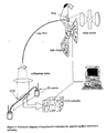
- the present invention relates to an optical assembly comprising a sample vessel positioned in a direct light path between a light source and a light detector, in manner to enable transmission of light through the vessel; a method for detection of light transmission through sample contained within the vessel; an apparatus comprising the assembly; more particularly an apparatus for sample analysis for example for high throughput screening (HTS) or profiling or assays, such as enzyme assays; and uses thereof in the pharmaceutical, biomedical and bioscience, agrochemical, veterinary, materials and like fields, for detection, analysis, characterisation and quantification or the like of samples contained in a vessel, and optionally further collecting separated components thereof; in particular in combinatorial chemistry; in metabolomics, proteomics or genomics, assay and high throughput analysis applications, typically high sensitivity analyses, separation and/or quantification studies and for sample separation for example chromatography or electrophoresis, in particular column chromatography, capillary electrophoresis with real time or post separation analysis.
- HTS high throughput screening
- profiling or assays
- UV absorbance, fluorescence and mass spectrometry are key technologies used in separation science for analysing species in samples.
- a particularly useful methodology is to look at a sample population separated by capillary electrophoresis with fluorophore labelling and fluorescence imaging, for quantification, and MS for characterising molecules of interest.
- US 5,582,705 discloses an apparatus and system for laser induced fluorescence (LIF) detection in a multiplexed capillary electrophoresis system.
- a coherent beam incident on the capillary array and emitted fluorescent light are typically perpendicular to each other in order to reduce background noise due to light scattering.
- a transparent portion in each capillary wall defines a transparent path extending through the array, perpendicular to the capillary.
- a 2D image array detector such as a charge-coupled device (CCD), preferably a charge-injection device (CID), is positioned to detect emission, and an imaging lens interposed between the capillary array and the image array detector, to optically couple the pixels to the capillary.
- CCD charge-coupled device
- CID charge-injection device
- the imaging lens may be any lens capable of transforming an image onto the pixels of the image array detector, such as a camera lens or a condenser lens. Coupling is shown in Figure 4, of US 5,582,705 in which every second pixel is coupled to a sidewall of the capillary and every pixel in between is coupled to an interior portion.
- Fluorescence detection is limited in its application since only a limited number of molecules are naturally fluorescent and many have to be derivatised in reproducible and quantitative manner. Absorbance detection therefore has the advantage of enabling detection of a wider range of molecules. For example in enzyme assays, conducted in microtitre wells, techniques can be extended to absorbance detection of chromophoric, UV and vis absorbing substrates consumed or produced in an assay, extending the range of assay to natural as well as synthetic substrates.
- absorbance detection is conducted on substrates in solution.
- many common solvents absorb significant amounts of light at wavelengths below ⁇ 200 nm, and the resulting solvent absorption signal distorts and masks signals resulting from the substrate to be detected.
- absorbance detection is in practice limited to detection at wavelengths in excess of 190 nm, in the range UV-vis to near infra-red (NIR).
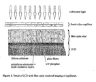
- a charge coupled device array detector for single-wavelength and multi-wavelength ultraviolet absorbance in capillary electrophoresis discloses optical detection in capillary electrophoresis by means of absorbance detection, illuminating a length of the capillary using a fibre optic bundle and using a charge coupled device (CCD) camera to image the full length of the illuminated zone.
- CCD charge coupled device
- WO 01/18528 discloses a method for analysing multiple samples simultaneously by absorption detection of samples in a planar array of multiple containers, whereby stray light from adjacent containers is eliminated by distancing the detection means from the array, preferably at a distance greater than 10 times the diameter of a container, suitable 10-100 times the diameter for example at a distance of 1-30 cm.
- Containers are preferably cylindrical capillary tubes as shown in the art.
- the array comprises a control container if the light source is unstable. It is stated that the cross section of the container and thickness of the capillary wall are not critical.
- a flat field lens preferably images the containers on to the detection means.
- EP 0 616 211 A1 relates to an optical detection arrangement for the analysis of fluid samples.
- US Patent No. 5,694,215 (Carver) relates to an optical array for use with an elongated sample cell assembly, adapted for use in spectroscopy of sample volumes in capillary chromatography and a method of measuring optical absorbance of light through a volume of sample material flowing in a flow direction through a sample cell.
- the improved assembly is of particular advantage in detection in multiplexed capillary arrays and enables imaging a large area of a capillary array without the need for imaging optics. This is a significant advantage, especially when working in UV for which it is very difficult and expensive to produce suitable optics.
- the assembly has benefits however in both single and capillary and array detection, in particular enabling a simple and improved exposure referencing and acceptably low intercapillary cross talk without the need for optics.
- a benefit of the assembly of the invention is that it is suitable for operation at short pathlengths, by virtue of the increased total light flux through the core of the capillary or other sample vessel, and this reduction in pathlength may lead to opportunities to conduct absorbance detection at lower wavelengths, less than 190 nm, without encountering impracticably high levels of solvent absorption.
- an optical assembly comprising a light source, at least one sample vessel and a detector, the at least one vessel being positioned in a light path or paths created between the source and the detector in manner to enable transmission of light through the vessel
- the light source is adapted to provide a beam of substantially collimated light
- the detector comprises a plurality of detector locations and the vessel comprises a wall and core of relative shape and dimensions adapted to contain a sample for detection and to define at least two spatially separated transmitted light paths, a first wall path which enters and exits the vessel walls only, spatially separated from a second core path which enters and exits the vessel walls and additionally the vessel core, wherein the spatially separated wall and core paths are coupled to individual detector locations on the detector and, the detector is an array detector.
- the detector is adapted to detect and provide information on respective wall and core path light transmission.
- the assembly is coupled to means for displaying information on respective wall and core path light transmission or for displaying referenced information on core path light transmission, referenced against wall path light transmission.
- the assembly defines a central core path and two peripheral wall paths either side thereof or an annular wall path thereabout. Paths may overlap on emerging from the vessel and at greater separations from the vessel.
- the wall and core paths are coupled to detector locations at a vessel outer wall to detector separation or distance d at which the paths are spatially separated, preferably giving more than 90% separation of core and wall beam fluxes.
- the assembly may position the vessel in two or more separate light paths to generate two or more sets of spatially separated transmitted light paths coupled to two or more detectors or detector zones.
- the assembly is characterised by internal vessel dimension or path length in the range 3 ⁇ m to 20 mm, external vessel dimension in the range 4 ⁇ m to 30 mm, refractive index of vessel wall in the range 1.3 - ⁇ 1.6, vessel outer wall to detector separation d in the range 10 ⁇ m to > 300 mm and is for use in detecting a sample comprising analyte in solvent having refractive index in the range 1.3 to in excess of 1.5.
- Reference herein to a sample is to vessel contents which may comprise a single or multiple components.
- Multiple components may be present as a homogeneous or heterogeneous mixture, and may undergo migration with time ie may be a plurality of liquid phase components optionally including a dissolved phase component; or may include one or a plurality of analytes which it is desired to detect in one or a plurality of solvents or like bulk phase sample component, for example in the course of a chemical reaction generating or consuming a species as analyte.
- the apparatus of the invention enables exposure referencing of a light beam traversing a core path of the at least one sample vessel, by a light beam traversing a wall path of the same sample vessel.
- the beams are spatially close, preferably adjacent, on the array detector, facilitating direct referencing as the ratio of the core beam to the wall beam.
- the two light beams are of neighbouring origin whereby core and wall beams have a high probability of emanating from the same region in the light source eliminating the effects of light source fluctuations due to e.g. instability or spatial inhomogeneity.
- the assembly of the invention is therefore able to operate at the shot noise limit.
- the light source comprises any active or passive light source, for example light may be generated at the source or it may be transmitted to the source and emanate therefrom, for example it may be transmitted by an optical fibre to the light source.
- the light source comprises at least one wavelength of light that is absorbed by one or more absorbing species, the absorbance of which is to be detected.
- the light source output may be coupled from a fibre optic if desired for illumination from a remote light generator or may be coupled from a point to line optical fibre for zone illumination. Coupling the output into a single optical fibre reduces noise contributions caused by fluctuations in the spatial distribution of the lamp discharge.
- Light may be of wavelength in the range 160 to 1200 nm, preferably 180 or 190 to 1200 nm, corresponding to UV, UV-vis to near infra red (NIR), and is preferably in the range 180 to 700 nm corresponding to UV-vis.
- NIR near infra red
- the present invention enables high sensitivity absorption detection at lower path length in the range 3 - 500 ⁇ m and this allows operation at lower wavelengths in the range 160 to 190 nm corresponding to UV which would be impractical for absorbance detection of samples in some solvents by known techniques. Accordingly the method is more solvent independent than normal HPLC or spectrophotometric methods.
- a light source may be a point or line source adapted to illuminate a section through a compact vessel or elongate vessel.
- a light source may be of single wavelength or multiple discrete wavelengths or wavelength range.
- a light source may be a tuneable light source, giving a tuneable smooth output, a line output lamp giving a very intense output at one wavelength only, a spectrum light source giving a wavelength range along the length of a line light source or the like; and may be continuous in time, or pulsed. Sources with continuous outputs are preferable when spectra are to be acquired over a wavelength range.
- -Line sources typically provide more intense outputs at characteristic wavelengths, and are beneficial when the samples absorb at these wavelengths.
- Wavelength selection in the case of continuous wavelength arc lamps for example is suitably by known technique such as interference filter positioned between the light source and collimating means or between the collimating means and the sample vessel, preferably before the collimating means.
- a filter wheel or variable interference filter may be employed for sequential wavelength detection at multiple discrete wavelengths, or a wavelength dispersing device may be employed in the form of a monochromator such as a grating or prism which may be either fixed in position or continuously variable and spreads light into a spectrum, giving a varied wavelength along the length of the capillary or at right angles to the length of the capillary.
- a light source comprises an iodine, zinc, cadmium or mercury lamp, or laser, as line sources; or a deuterium, xenon or tungsten lamp as continuous output lamp; or a xenon lamp as a pulsed output lamp.
- the light source comprises a deuterium arc lamp (for UV light absorption) or a xenon arc lamp (for UV-vis light absorption); or comprises a tungsten lamp, more preferably a filament lamp (for visible light absorption), and the like; most preferably a high output arc lamp selected from deuterium, iodine, zinc, cadmium, mercury or xenon above; or the light source comprises a line source, preferably for the UV one of the following: iodine, zinc at 214 nm, cadmium at 229 nm, or mercury at 185, 254 or 365 nm; or the light source comprises a laser, for example in the UV a laser such as a frequency quadrupled Nd:YAG at 266 nm or Nd:YLF at 262 nm, or a He-Cd laser at 325 nm.
- a laser for example in the UV a laser such as a frequency quadrupled Nd:YAG
- the light source may be expanded and recollimated by known means, for example using cylindrical and spherical lens elements and the like, preferably using an elongate lens or cylindrical optical component, such as a cylindrical fused silica lens or the like, to produce a collimated beam suitable for zone illumination of a sample vessel array.
- known means for example using cylindrical and spherical lens elements and the like, preferably using an elongate lens or cylindrical optical component, such as a cylindrical fused silica lens or the like, to produce a collimated beam suitable for zone illumination of a sample vessel array.
- the at least one sample vessel in the assembly of the invention may comprise a cell or conduit which may be-closed or open ended and closed-or-open based and topped, intended for static or dynamic sample detection.
- the vessel may be aligned for light transmission in any suitable plane through the vessel.
- light transmission is through a plane perpendicular to or containing the vessel ends or base and top.
- the sample vessel is a single cell or one of a plurality of cells in an array, such as a rectangular or square array, for example in a microtitre plate, well plate or multi sample plate; or is a capillary, such as a microcapillary or microfabricated channel as known in the art of microfluidic transport and separation, more preferably is a single capillary or microchannel or one of a plurality of capillaries or microchannels in a parallel array.
- an array such as a rectangular or square array, for example in a microtitre plate, well plate or multi sample plate
- a capillary such as a microcapillary or microfabricated channel as known in the art of microfluidic transport and separation, more preferably is a single capillary or microchannel or one of a plurality of capillaries or microchannels in a parallel array.
- a sample vessel array is aligned in a plane perpendicular to the collimated light path whereby light passes through one vessel only.
- direction of illumination is in a plane containing the vessel base and top
- light enters and exits each vessel through a sidewall (wall path) or enters through the top and exits through the base (core path)
- vessels may be aligned in a parallel or matrix array;
- illumination is through a plane perpendicular to the vessel ends, light enters and exits each vessel through a near side sidewall (wall path) or enters and exits through a nearside sidewall, emerges into the core, enters and exits an opposing sidewall (core path), and in this case vessels may be aligned in a parallel array, ie only one vessel deep.
- the collimated light path has dimensions substantially corresponding to the dimensions of width and length of the detector array and to a desired width and length of each sample vessel which it is desired to optically detect.
- Illumination:detection magnification is preferably in the range 0.8 -1.5:1 in the case of arrays to avoid problems with spatial overlap of light from neighbouring vessels, and is in the range 0.5 - 2:1 for single vessels.
- the vessel of the assembly is a microfabricated device providing square cross section capillaries, and is suitable for Fabry-Perot illumination with enhanced light absorption through multiple passages through the vessel.
- the walls of the vessel are coated with a reflective coating, within an absorption zone, whereby light enters the vessel core in an illumination zone adjacent the absorption zone, through a nearside side wall, at an angle less than 90 degrees to the wall, and at least a portion of light is reflected at the opposing wall, with repeated internal reflections throughout the absorption zone and finally emergence from the opposing wall at the end of the absorption zone.
- Light traversing a wall path may be similarly reflected for ease of alignment but is preferably not reflected and exposure referencing is performed as normal.
- the optical assembly of the invention is characterised by refraction patterns through the vessel in order to be able to spatially separate wall and core light paths.
- the assembly is characterised by respective outer and inner diameter of a sample vessel, and by respective refractive indices of vessel walls and of sample, whereby the wall and core paths are spatially separated as hereinbefore defined.
- the refractive index of the vessel wall is greater than that of the bulk phase of any sample comprised in the core.
- refractive index of the wall is in the range 1.34 - 1.59.
- refractive index of bulk phase sample comprised in the core is in the range 1.32 - 1.48 more preferably 1.32 - 1.38.
- the refractive index of vessel wall may be modified by cladding or otherwise incorporating higher refractive index material in the vessel wall as a wall section, lens or the like.
- the vessel outer wall and inner wall are additionally of shape and dimension whereby light transmitted through the core is convergent and forms a beam having an undeflected beam path, i.e. having a beam path continuous with the incident collimated light.
- Light passing through the wall of the sample vessel only, entering the wall at one outside wall location and exiting at a second outside wall location may be deflected or undeflected, preferably if deflected is divergent with respect to the core light path such that two classes of light paths are formed which are spatially separated.
- the light path passing through any point of the vessel can be predicted for any given shape and dimension of vessel outer wall and inner wall, chosen such that collimated light passing through a square or rectangular cross section vessel, normal and parallel to respective walls, emerges substantially unrefracted and parallel; and collimated light passing through a curved or angular cross section vessel emerges uniformly divergent or convergent with a gradation in angle of refraction.
- This enables production of an emergent light path of high symmetry and/or uniformity, which can be manipulated for imaging and exposure referencing as hereinbefore defined.
- the at least one sample vessel has a cross-section in a plane including the transmission light path, which is square or rectangular, curved circular or angular or a combination thereof and is symmetrical or asymmetrical, preferably is symmetrical.
- the sample vessel moreover comprises an outer and inner wall which may be of similar cross-section or shape or may be different, for example one may be circular and one square.
- the sample vessel wall through the cross-section may be continuous or noncontinuous, for example the vessel may be open or closed and is preferably closed.
- a closed vessel may have a continuous wall through its cross-section or may comprise continuous base and side walls with a separate seal or lid.
- the outer wall is square open or closed or circular closed
- the inner wall is square or well shaped open or closed or is essentially square with microfabricated convex or concave inner wall sections acting as lens faces, or concave, convex or prism shaped outer wall sections acting as lens faces.
- At least one of the outer and inner walls of the sample vessel is of circular cross-section, whereby refraction and spatial separation of core and wall beams is achieved, preferably outer and inner walls are of coaxial circular cross-section thereby defining an annular wall having outer and inner diameters such that refraction and spatial separation of core and wall beams is achieved.
- sample vessel dimensions, refractive indices and/or vessel to detector distance may be selected according to the nature of vessel wall material and shape and the sample to be contained within the core in order to achieve the desired refraction and spatial separation.
- the apparatus is defined by a relation of the following properties which are shown here as a flow scheme rather than as a mathematical relation: i . d o . d . + r . i . solvent + r . i . vessel ⁇ d min o . d . ⁇ d min where + infers a spatial relation which would be calculated using suitable ray tracing software to give values for vessel and assembly dimensions.
- ray tracing for example using Zemax software, may be used to produce diagrams allowing relationships between dimensions such as dmin / o.d. to be deduced.
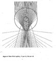
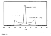
- Figure 5 A schematic diagram showing the cross section of a cylindrical vessel and the surface of the detector is shown in Figure 5: symbols, given here in brackets, are for the inner diameter (i.d.), the outer diameter (o.d.), and the outer wall to detector distance ( d ).
- the minimum distance for spatial separation of the core and wall beams using collimated light incident on the vessel may be calculated from values given in Table 1.
- the minimum value of d /o.d. is 0.5 and thus the minimum value of d is 100 ⁇ m.
- the vessel may be associated with additional optical components in the emergent light path, to focus or otherwise manipulate one or both of the spatially separated beam types.
- the array may comprise fixed or variable spacers between each sample vessel for adjusting spacing of emergent beams B in a sequence for vessels 1 2 3 etc, as shown in Figure A, having wall w and core c, for example wherein each beam corresponds to an array detection location:
- Spacers may comprise elongate filters designed to screen all or part of a wall light path, or a filter to screen part of the vessel wall thereby confining the wall light paths, in both cases for minimising intercapillary stray light and cross talk.
- a spacer may therefore be of any suitable material for combined spacing and filtration, optionally also serving as support means for the at least one sample vessel, and is of suitable opaque material such as for example an opaque glass filled polymer.
- Sample vessels may be comprised of any transparent polymer, glass, quartz, silica, e.g. fused silica or other material, preferably optical grade.
- Optical grade polymers include the classes of siloxanes such as polydimethylsiloxane (PDMS), amorphous polycycloolefins based on norbornene, and polymethylmethacrylate PMMA, polycarbonate, and other transparent flexible polymers and fluoropolymers.
- Flexible transparent polymers are commercially available as transparent flexible tubing such as polyetherimide such as Ultem, polypropylene, fluoropolymers including the transparent PCTFE, ECTFE, ETFE, PTFE, PFA, FEP or PVDF resins, preferably the fluoropolymer Tygon chemfluor 367 and the like.
- the vessel wall may be transparent in part or whole and is preferably of the same material throughout.
- a capillary as hereinbefore defined may comprise any extruded capillary or microfabricated capillary or channel or other parallel elongate closed conduit means.
- a capillary may be flexible or rigid and may be straight or curved along all or part of its length.
- Capillary arrays and microfabricated channel arrays are commercially available. Capillary arrays are typically manufactured by drawing or extrusion, creating a void circular cross-section core of high uniformity dimensions. Microfabricated arrays are typically manufactured by injection moulding from a tool, creating a void square or rectangular cross-section channel, which is then optionally sealed with a cover layer, and offers the advantage of absolute reproducibility of highly precise channels, and freedom of channel design.
- a sample vessel may comprise part of an array of any number of vessels, commercially available arrays include 8 to 1536 vessels, preferably 8 to 520 capillaries or 96 to 1536 wells, for example 8, 12, 16, 24, 32, 48 or 96 capillaries or 96, 384 or 1536 wells.
- the vessel may comprise part of an array of a greater number of vessels which may be available in the future.
- Micro fabricated arrays fabricated in layered planar manner, constructing interfacing elements of a device in sequential planes, are gaining acceptance and widespread use. They have numerous advantages in accuracy, reproducibility, ease and flexibility of manufacture.
- Vessels may have any desired separation, suitably are fused or adjacent or are spaced apart.
- a lower separation increases packing density but a higher separation reduces intervessel interference, in particular optical interference. It is a particular advantage of the invention that intervessel spacing may be used. This is not possible in the embodiment of Yeung et al above, for example which needs minimal vessel separation to minimise stray light.
- the vessel may be of suitable length and depth according to the desired use.
- length is in the range 2 cm - 2 m for example in the range 2.5 - 6 cm for microfabricated channels or 6 - 100 cm length for capillaries, more preferably 10 to 60 cm. Greater length allows application of higher voltage in capillary electrophoresis and improved separation.
- preferable inter-vessel centre to centre spacings are compatible with standard microtitre plate formats, such as 2.25, 4.5 and 9 mm.
- a vessel is of 3 ⁇ m to 20 mm in depth or internal diameter, and 4 ⁇ m to 30 mm in external diameter, more preferably 9 ⁇ m - 3 mm in depth or internal diameter and 10 ⁇ m to 3.5 mm in external diameter, more preferably 10-380 ⁇ m, most preferably less than or equal to 200 ⁇ m in depth or internal diameter or external diameter.
- a vessel wall is importantly of suitable thickness for the optical properties of the invention. This is particularly relevant for vessels of small internal diameters. Accordingly vessel internal diameter or "bore" may be selected and vessel wall material selected, and suitable outer diameter determined accordingly to give the required optical properties.
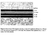
- o.d. For silica capillaries with internal diameter (hereinafter i.d.) in the range 20 to 250 ⁇ m, for example 20, 25, 50, 75 or 100 ⁇ m, external diameters (hereinafter o.d.) is preferably in the range 100 to 380 ⁇ m, for example 150, 200 or 360 ⁇ m.
- a vessel may be of 75-100 ⁇ m i.d. and 194 ⁇ m o.d. or 180 ⁇ m i.d. and 364 ⁇ m o.d.. It is important to note that for a vessel with 75 ⁇ m i.d.
- thickness is suitably in the range 30 - 500 ⁇ m, for example 30 - 150 ⁇ m: vessels of low i.d. preferably have low wall thickness, to give a minimum i.d. to o.d. ratio of 2 - 4 for example 0.25.
- a glass reaction vessel having an i.d. of 20 mm and an o.d. of 30 mm has an i.d./o.d. ratio equal to 0.67, which permits beam separation with all common solvents (see Table 1).
- a polycarbonate reaction vessel and water as solvent for an i.d. of 0.33 cm, an o.d. of 1.0 cm would be suitable, but an o.d. of 1.5 cm would be unsuitable.
- Tygon chemfluor 367 for a representative fluoropolymer tubing, Tygon chemfluor 367, with i.d.
- the i.d./o.d. ratio is 0.50 and beam separation with solvent water is achieved for all values of the ratio d /o.d. greater than 0.4, i.e. d > 1/20" (1.3 mm).
- the refractive index of the vessel contents is greater than that of the walls (values of refractive indices are given in footnote to Table 1), and no beam separation is possible other than at distances unreasonably close to the vessel outer wall.
- the sample vessel may be void or packed, for example may comprise stationary phase or may be coated or otherwise configured with suitable materials as known in the art for example in HPLC. Suitably packing if present is of corresponding refractive index to bulk phase sample or to solvent comprised in sample to be detected.
- the vessel comprises internals and components characteristic of columns or capillaries present in pressure driven or electrical driven separations including HPLC (for pressure driven) or capillary electrochromatography (CEC) (electrically driven equivalent of HPLC, separating by binding or partition coefficient, using eg hydrophobic stationary phases), micellar electrokinetic chromatography, and capillary electrophoresis (CE) including the focusing and concentrating techniques of isoelectric focusing (IEF separating by isoelectric point independent of size and shape of molecules), isotachophoresis (ITP), capillary zone electrophoresis (CZE separating by charge to size ratio) and dynamic field gradient focussing (DFGF, where a constant hydrodynamic force is opposed by a gradient in the electric field, which allows charged molecules to focus in order of their apparent electrophoretic mobilities and selective concentration of analytes e.g. proteins - see "Digitally controlled electrophoretic focusing" Huang and Cornelius, Anal. Chem., 1999, 71, 1628-1632).
- HPLC for pressure
- the separation between a sample vessel and the detector, d is suitably such as to facilitate coupling of spatially separated light paths to the detector locations.
- the separation is a function of the vessel o.d. and of the degree of separation of light paths, and is preferably given by the ratio d /o.d. is less than 10, for example is in the range 0.5 - 5, preferably 0.5 - 1.
- the optical assembly of the invention allows an extremely compact structure when working with capillaries in which separation d is of the order of 50 - 360 ⁇ m, for example 200 ⁇ m. This is particularly advantageous since the lesser the value d the more compact and robust is the assembly and the more intense are the transmitted light beams at the detector.
- the separation d may be adapted to couple spatially separated light paths in sequence as hereinbefore defined, with or without intervening optical components and preferably without intervening optical components.
- CMOS complementary metal oxide semiconductor
- an array detector according to the invention comprises a solid state sensing device, more preferably a CCD, CID or a CMOS APS.
- a detection zone may be of any desired area size and is suitably of zone dimensions substantially equal to the vessel or array cross section in a plane perpendicular to the light path, corresponding to one to one image.
- a detection zone may comprise one or a plurality of array detectors.
- the apparatus comprises lowest noise and highest sensitivity CCDs in a relatively small area device, such as a 1024 x 256 pixel CCD (MAT CCD30-11).
- a CCD for use in the apparatus of the invention may have 22 to 5000 or more pixels in either dimension, preferably 256, 512, 770, 1152, 2048 or 4096 pixels, of pixel size 7 to 35 ⁇ m, preferably 20 to 30 ⁇ m, more preferably 22 to 30 ⁇ m.
- the CCD comprises 3 to 28, for example 10 pixels per capillary or 30 to 2500 for example 100 pixels per well. Pixels outside the imaging area are preferably not digitised to reduce readout time.
- CCDs may include a stud, for protection of the CCD surface which is usually recessed in the CCD support package and to conserve image quality.
- the stud comprises a coating to absorb incident light and reemit at a different wavelength, to convert UV to visible light, to allow detection by the CCD.
- a coating is for example a phosphor coating.
- the phosphor coating may be applied directly to the stud or to a cover slip interleaved between the stud and capillary, facilitating changing phosphor as needed, by replacing the cover slip without need-to-replace the stud.
- Each camera is interfaced to control means, preferably a processing control means providing a suitable pixel readout rate, suitably of the order of MHz, preferably greater than 4 or 5 MHz.
- the processing means is programmed for selection of on-chip charge binning procedures, to increase signal current (photoelectrons per second) and selection of area of interest for read out. Additionally the processing means controls camera readout and collects, stores and analyses data.
- the apparatus operates with real-time signal processing for optimum peak detection and parameterisation/characterisation, and potential for automatic system management including closed-loop feedback control of the apparatus and systems.
- feedback could include stopping or slowing the flow following initial observation in the detection window, to allow sample to reside in the detector window and give longer-times for data acquisition and enhanced signal to noise or to facilitate detection along the length of a vessel.
- Flow velocity may be controlled by adjustment of electric field (as in capillary electrophoresis) or by adjustment of pressure (as in liquid chromatography), or by a combination of the two.
- flow velocity control is carried out by adjustment of the angular velocity.
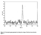
- the assembly comprises means to detect presence of sample in a detection window, and feedback control means for turning off the voltage when it is detected as having migrated to the centre of the window (see Figure 13).
- Feedback control means suitably includes means for monitoring the subsequent broadening of the sample peak due to diffusion as a function of time, and for analysis of the change in peak variance with time, and determining the diffusion coefficient, enabling the hydrodynamic radius of the analyte to be deduced, and means for combining with the mobility, obtained from the time taken to reach the window under a given field strength, enabling the charge on the analyte to be deduced.
- the control means is able to operate with any starting peak shape, since convolution of the peak with a Gaussian enables the Gaussian component of the peak broadening to be extracted.
- Data quality obtained with the assembly of the invention is such that diffusion coefficients could be measured with good precision in less than 3 minutes.
- This assembly could be used to measure diffusion coefficients, size and charges of both small molecules and large molecules, including proteins, DNA, and polysaccharides, and offer a simpler alternative to analytical ultracentrifuge methods.
- closed loop feedback could include means such as peak recognition and decision making software for instructing a switching valve and controlling switching times to enable fraction collection, or to direct a fraction to a mass spectrometer, e.g. via an electrospray interface, or to a NMR spectrometer.
- Means for observing the flow stream both before and after the valve enables the quality of analyte switching and efficiency of the switching means to be monitored.
- a schematic example of closed-loop feedback control is given in Figure 14.
- the assembly positions the capillary in two separate light paths and to generate two sets of spatially separated transmitted light paths coupled to two detectors or detector zones with the switching valve therebetween whereby after the appropriate switch the eluent is monitored again in a second pass of the detector, so that the efficiency of the switching process can be monitored.
- An alternative is to have more of the outputs of the switching valve passing the detector for visualisation.
- Closed loop feedback may also include controlling velocity of samples in multiple vessels, for example in a capillary array, to co-ordinate exit times, in sequence or, for combining samples from different capillaries into a common exit means, simultaneously.
- Velocity may be controlled by controlling voltage or pressure, for example pumping flow rate, and may be operated with switching devices. Velocity may enable stopping samples flow at desired time to coincide with an event which is to be performed on the sample or is to take place in the sample.
- Controlled exit may be for subsequent fraction collection or analysis, for example for interfacing the output of a capillary bundle to a mass spectrometer by electro-spray, or to an NMR spectrometer or the like.
- controlled loop feedback is provided by creating a potential difference across the length of the capillary and/or varying the applied voltage to control migration of sample, including slowing or stopping to improve signal/noise ratio and including timing sample migration to achieve a desired time of arrival of sample at a point to switch into a sample collection means such as mass spectrometer.
- the system may operate with a pressure difference and pumping, electrical field driver, column switching or the like.
- a capillary comprises electrodes, valves or pressure regulators at the ends thereof or along the length thereof about the detection zone or each detection zone together with circuitry to control electrodes or to facilitate pumping control.
- a sample vessel is connected to a buffer supply and electric field is arranged such that buffer supply and sample introduction is at the high potential end of the capillary, where high may be either positive or negative with respect to ground.
- an optical assembly module for use with a column or capillary separating device as known in the art, wherein the vessel is a capillary or column comprising interfacing means at one end for inserting into the outlet of a column or capillary separating device and optionally comprising interfacing means enabling insertion into the inlet of an analysing means at the other end or comprising interface means at both ends for insertion along the length of a capillary or column.
- a module for insertion along the length of a column or capillary typically has a column or capillary section of matching i.d and o.d as the separating device or interfacing means allowing a smooth flow transition.
- an optical assembly clip-on device adapted to locate about a section of a capillary or column which is of suitable i.d, o.d and refractive index as hereinbefore defined comprising means to locate about the capillary or column of a separation device.
- the capillary or column has its outlet inserted into the mass spectrometer, in which case the clip-on is located as close to the mass spectrometer as possible.
- the capillary or column of the separation device may be stripped of any surface coating to facilitate the operation of the method of the invention, whereby the stripped capillary or column, such as a capillary electrophoresis or microbore HPLC section, provides the sample vessel of the assembly.
- an apparatus for chemical reaction or synthesis and analysis or for sample separation or transport wherein the apparatus comprises the optical assembly as hereinbefore defined.
- the chemical reaction vessel itself could be cylindrical and the reaction monitored in batch flow mode as a function of time, and feedback control used to halt reaction - e.g by admixture of a quenching reagent, by change of temperature, or by exporting the vessel contents.
- the reaction vessel could be tubular and used in continuous flow mode.
- the apparatus may comprise a plurality of means for introducing one or more reagents to the at least one sample vessel together with means for regulating reaction conditions to form a desired chemical synthetic reaction within the at least one sample vessel; or may include means for inlet and outlet of sample in dynamic fashion into the at least one sample vessel together with means for applying a pressure difference or potential difference across the ends of the vessel and means for supplying separation mediums such as buffer in order to perform separations within the at least one sample vessels: or may include a separation means such as a chromatography column as known in the art having outlet interfaced with an inlet end of the at least one sample vessel as hereinbefore defined for dynamic analysis of separated sample.
- a method for detection of light transmitted through at least one sample contained within the core of at least one sample vessel of an optical assembly as hereinbefore defined comprising illuminating the vessel with a substantially collimated light source or sources and detecting transmitted light in a detector, wherein transmitted light is spatially separated into at least two light paths, a wall path which has passed through the vessel walls only, spatially separated from a core path which has passed through the walls and core, wherein the spatially separated light beams are coupled to individual detection locations on the array detector.
- the method comprises any features or embodiments corresponding to apparatus features and embodiments outlined above.
- the method is a method for detecting light from samples in sample analysis for example for high throughput screening (HTS) or profiling or assays, such as enzyme assays; and uses thereof in the pharmaceutical, biomedical and bioscience, healthcare, agrochemical, veterinary, industrial, environmental or materials or like fields, for detection, analysis, characterisation and quantification or the like of samples contained in a vessel, and optionally further collecting separated components thereof; in particular in combinatorial chemistry; in metabolomics, proteomics or genomics, assay and high throughput analysis applications, typically high sensitivity analyses, separation and/or quantification studies and for sample separation for example chromatography or electrophoresis, in particular column chromatography, capillary electrophoresis with real time or post separation analysis, in hospital or surgery blood tests and other assays, in industrial quality control, in environmental pesticide level monitoring and the like.
- HTS high throughput screening
- profiling or assays such as enzyme assays
- the method may be a method for detecting light from a static or dynamic sample.
- a static sample is contained in a closed ended sample vessel as hereinbefore defined, more typically in a vessel in the form of a cell or well which may be one of a plurality of vessels for example in a microtitre plate or a well plate or sample plate as hereinbefore defined.
- Samples derived from enzyme assay or other multiple sample analysis may be in this form for detection.
- the method is a method for single capillary or multicapillary absorbance detection, comprising drawing solvent then sample into the capillary(s), by capillary action, pressure, pipetting or the like, conducting detection of difference in transmittance of sample and solvent, and disposing of or blowing sample back to the source.
- This method is useful in bioscience for making absorbance measurements on small sample volumes of microlitres or less.
- Enzyme assays may be conducted with one or two streams entering the vessel and detecting a time dependent change, normally in profiling, for enzyme assay.
- Typical dynamic samples are electrically or pressure driven and are present in an open ended conduit type vessel as hereinbefore defined, such as a capillary having inlet and outlet ends for flow of sample through the capillary
- the capillary may be a single capillary or part of a capillary array as hereinbefore defined.
- Samples derived from high throughput screening or from the separation or transport techniques may be provided in this manner for detection, of which samples derived from separation techniques may be provided for separation within the capillary with simultaneous detection of light transmission, or may be separated in a separation method such as column chromatography, and the separated sample flow from the column coupled directly into a capillary for detection of light transmission.
- the method for detecting a dynamic sample is a method for column or capillary separation as known in the art, suitably selected from pressure driven or electrical driven separations including HPLC (for pressure driven) or capillary electrochromatography (CEC) (electrically driven equivalent of HPLC, separating by binding or partition coefficient, using eg hydrophobic stationary phases), micellar electrokinetic chromatography, and capillary electrophoresis (CE) including the focusing and concentrating techniques of isoelectric focusing (IEF separating by isoelectric point independent of size and shape of molecules), isotachophoresis (ITP), capillary zone electrophoresis (CZE separating by charge to size ratio) and dynamic field gradient focussing (DFGF, where a constant hydrodynamic force is opposed by a gradient in the electric field, which allows charged molecules to focus in order of their apparent electrophoretic mobilities and selective concentration of analytes e.g. proteins - see "Digitally controlled electrophoretic focusing" Huang and Cornelius, Anal. Chem.,
- a method which is a method for electrophoretic separation of molecules is carried out with an assembly, module or clip-on in a capillary or channel as hereinbefore defined which is connected to a buffer supply.
- An electric field in the range of kilovolts is applied across both ends of the capillary or channel to cause the molecules to migrate.
- Samples are typically introduced at a high potential end and, under the influence of the electric field, move toward a low potential end of the channel.
- Absorbance analysis may be conducted along the length of the capillary or channel or near the outlet allowing observing an entire process taking place in the length of the capillary or channel or the result thereof.
- Another use of dynamic detection is in measuring refractive index change.
- the detector By analysis of the illumination pattern of the core beam at high spatial resolution perpendicular to the capillary axis, the detector has the ability to monitor refractive index change in the solvent in the capillary. This would allow distinction between two solvents, and by extension the ability to directly monitor the mobile phase composition during a gradient elution separation in dual solvent mixtures. If necessary, magnification in the direction perpendicular to the capillary axis could be used to increase the resolution in terms of mobile phase composition. This would be of benefit in HPLC. Since solvent refractive index may be temperature dependent, application of a heat pulse providing a temperature rise up-stream of the detector could be used to determine the mobile phase velocity in capillary HPLC.
- Another use of multicapillary absorbance detection is for rapid measurement of p K a .
- aliquots of the sample solution are mixed into a set of buffer solutions covering a range of pH values, typically spanning the range 2-12, and all mixtures are then drawn up into separate capillaries in the sequence buffer then mixture of buffer plus sample.
- results from all capillaries of absorbance as a function of pH may be processed to determine p K a values.
- suitable non- or weakly-absorbing inorganic buffers this is applicable for organic or biological compounds containing all common titratable functional groups, including carboxyl and amine groups, and at concentrations down to 100 micromolar. This is of benefit in for example the pharmaceutical industry and for high throughput screening.
- the invention has particular use in relation to samples of small molecules of MW of the order 15 - 500, but may also be used in relation to samples of larger molecules such as polymers, proteins, DNA and other biomolecules of MW of the order 500 to 10 6 .
- the invention is of particular advantage in one embodiment due to its small size. This may be employed to advantage in hospitals and the like for sample analysis, without the need for clinical biochemical laboratories, for example as a colour assay. Blood tests may be conducted on blood samples which are currently spun to separate red blood cells and plasma in a laboratory.
- the assembly of the invention may be used to detect red blood and plasma, either before or after centrifugation, for example by adding a reagent to the plasma region and observing the reaction.
- multiple wavelength detection allows detection at a range of wavelengths along the length of a capillary or channel.
- the method is a method enabling or allowing some transformation or event to occur in a vessel and imaging the event. Imaging may be conducted at the end of the transformation or event or throughout. Imaging throughout an event requires timing to coincide with migration of sample in the vessel, preferably using controlled loop feedback as hereinbefore defined to stop the sample migration in the vessel at desired location or interval for imaging.
- the method may be a method for observing a chemical reaction for biomedical, bioscience, healthcare, agrochemical, veterinary, pharmaceutical, industrial or environmental purpose, wherein multiple detection may be performed on the inlet and outlet and in the waste to ensure that all of the reaction product has been collected.
- the reaction may be conducted in the vessel in the form of capillary which may be curved, allowing ease of detection of multiple positions using a common light source and detector.
- the method comprises detecting sample from pharmaceutical studies, in the form of analyte in solvent such as dimethylsulfoxide (DMSO), stored in microtitre plates, as is common in pharmaceutical practice.
- DMSO dimethylsulfoxide
- the method of the invention may be performed on samples either in the microplate array in situ, as a vessel array as hereinbefore defined or following drawing up portions into one or more capillaries, as a single capillary or capillary array.
- the method is a method for measuring physicochemical properties for example partition coefficients, comprising placing sample of analyte in a first solvent in the vessel, together with a second immiscible solvent, for example water and octanol respectively, and observing the analyte moving between the two immiscible phases.
- a second immiscible solvent for example water and octanol respectively.
- the method may be a method for detection of light from a plurality of sample vessels for high throughput analysis of different samples in each vessel, for example for comparative analysis thereof or may be a high loading method for detecting in each vessel the same samples from a high volume, high flow or otherwise bulk upstream process, intended for combining a desired component from each sample.
- a high loading method may comprise introducing the output from a single HPLC for example having flow rate exceeding that possible in a single capillary, but suitable for introducing into a capillary array which may then function effectively as a single detector.
- the method may comprise detecting analytes present in sample in or exiting a microbore liquid chromatography column and the column may be of diameter in the micron range up to millimetre range.
- High loading in a plurality or array of vessels achieves higher resolution in separation and potentially higher sensitivity in detection than operation on a large scale in a single vessel from a single large bore separation channel. Moreover a shorter path length is possible in an array of capillaries than is possible in a standard HPLC cell and this allows operation at a lower wavelength as hereinbefore defined.
- a method for detection in DFGF or multiple detection method preferably employs feedback control as hereinbefore defined.
- the method comprises illuminating the at least one sample vessel with collimated light comprising a single or a plurality of wavelengths selected in the range as hereinbefore defined.
- illumination is with a collimated light source of a single wavelength at any given time, thereby simplifying readout of optical detection results.
- a sample as hereinbefore defined may comprise any sample of one or more small or large molecules present in liquid or gel phase suitably in solution with liquid phase solvent or cosolvent such as an inert or non reactive liquid.
- Solvent or gel may have refractive index in the range as hereinbefore defined.
- these samples are characterised by a refractive index of lower than but of similar order to that of the sample vessel walls, whereby the sample provides a generally convergent light path.
- the sample comprises a solution or a suspension of molecules to be detected in a solution or suspending medium selected from water, alcohols, acetonitrile, hexane, dichloromethane, acetone, DMSO and other common solvents and cosolvents and mixtures thereof; or the sample may be provided in the form of a gel for example uncrosslinked polymer solutions such as cellulose derivatives (e.g. hydroxypropyl cellulose) and synthetic polymers (e.g. polyethylene oxide).
- a solution or suspending medium selected from water, alcohols, acetonitrile, hexane, dichloromethane, acetone, DMSO and other common solvents and cosolvents and mixtures thereof; or the sample may be provided in the form of a gel for example uncrosslinked polymer solutions such as cellulose derivatives (e.g. hydroxypropyl cellulose) and synthetic polymers (e.g. polyethylene oxide).
- the method of the invention comprises selecting a sample for analysis, determining individual wavelengths at which absorption by desired sample components is strongest, checking refractive index of the sample in order to select a suitable sample vessel which when containing the sample and when illuminated will generate spatially separated beams as hereinbefore defined or selecting a suitable combination of optical components, filters and the like and a suitable vessel to detect an array separation to couple spatially separated beams to independent locations on the detector array.
- Sample may be introduced into the at least one sample vessel as hereinbefore defined in known manner, for example by injection, loop injection, pipette, hydrostatic, electrokinetic or like injection techniques and may be removed from the vessel in known manner such as injection, electrospray or other interface for discard or to a further vessel for storage or to a down stream identification means such as mass spectrometer.
- Detected light is coupled to individual detection locations on the array detector as hereinbefore defined.
- the at least one sample vessel as hereinbefore defined is coupled to a plurality of detector locations in manner that core detector locations correspond to the core light path from the at least one vessel and peripheral detector locations correspond to the peripheral wall point(s) from the vessel.
- the method comprises imaging the transmitted light detected by the detection means, for example in the form of a CCD image as known in the art.
- the method also comprises referencing the light detected by the detection means by means of exposure referencing wherein the ratio of the core beam intensity to the wall beam intensity gives a value for the sample intensity at each location with elimination of excess or flicker noise due to light source fluctuation.
- the method comprises coupling the at least one sample vessel to at least three detector locations, preferably 3 to 25 detector locations for a sample vessel of the order of microns diameter wherein the locations may be apportioned for example 1:1:1 - 5:15:5 or 8:9:8 depending on the relative wall and core beam width; and for a sample vessel of the order of cm in an amount of 30 to 2500 pixels per sample vessel for example in the ratio 5:20:5 or 10:10:10 to 500:1500:500 or 800:900:800 depending on the relative wall and core beam width.
- the method may include pixel summing or the like for enhanced signal strength and noise reduction as known in the art.
- the method includes subsequently measuring the amount of absorption of light by species in the sample vessel which indicates the amount of absorbing species in manner as known in the art and comprising measuring the intensity of light in the absence and presence of the sample.
- measurement according to the invention is simply by measuring intensity of light in a wall beam and a core beam. The logarithm of the ratio, taken in conjunction with values measured in the absence of sample, provides the absorbance according to the Beer-Lambert Law.
- the optical assembly, method and apparatus as hereinbefore defined in sample analysis for example for high throughput screening (HTS), for example in an array as hereinbefore defined, or profiling or assays, such as enzyme assays; and uses thereof in the pharmaceutical, biomedical and bioscience, healthcare, agrochemical, veterinary, materials, industrial, environmental, and like fields, for detection, analysis, characterisation and quantification or the like of samples contained in a vessel, and optionally further collecting separated components thereof; in particular in combinatorial chemistry; in metabolomics, proteomics or genomics, assay and high throughput analysis applications, typically high sensitivity analyses, separation and/or quantification studies and for sample separation for example chromatography or electrophoresis, in particular column chromatography, capillary electrophoresis with real time or post separation analysis; in hospital or surgery blood tests and other assays, in industrial quality control, in environmental pesticide level monitoring and the like.
- HTS high throughput screening
- profiling or assays such as enzyme assays
- the experimental setup is shown in Figure 1.
- the output from a 75 W xenon lamp is launched into a single 1 mm diameter fused silica fibre.
- the light output from the fibre is shaped and collimated using cylindrical and spherical fused silica lens elements (Figure 2) to illuminate the rectangular area of the CCD.
- the CCD chip used is EEV CCD 30-11 and is thermostatted and controlled by a system designed and built by York Electronics Centre; it has 1024 by 256 active pixels, each 26 ⁇ m square, with a total active area of 6.7 x 26.6 mm.
- the CCD chip has a fibre optic stud (faceplate) that protects the CCD surface.
- the fibre optic stud is not UV transparent, so a UV phosphor is coated onto the surface of stud to make the detector sensitive to a wide wavelength range from NIR to below 200 nm.
- the charge accumulated on the CCD is read out in a series of snapshots; to prevent image smearing a light chopper ensures that the CCD is not illuminated during the readout period.
- An exposure rate of 5 Hz is used with a 50% duty cycle (100 ms exposure and 100 ms readout time).
- An image of 1024 ⁇ 256 pixels with 14 bit digitisation is obtained from each snapshot.
- An ideal arrangement of the capillaries could be to align them parallel to the short axis of the CCD at a spacing of 260 ⁇ m (10 pixels per capillary). This arrangement would allow up to 102 capillaries, which is ideal to accommodate the number used if sampling from a standard 96 well plate.
- the spacing means a gap of 66 ⁇ m between each capillary, this would allow more reference light reaching the CCD than in the current arrangement with the capillaries more tightly packed. Better exposure referencing and lower inter capillary cross talk should result from this arrangement.
- a series of parallel capillary electrophoresis experiments were carried out using a pH 7.5, sodium phosphate buffer (15 mM sodium) on dilutions of a 4-nitrophenol solution made up in buffer. Injections were performed inserting the inlet end of all the capillaries into the sample solution that was held at 2 cm above the level of the buffer in the outlet vial for 15 s. The volume injected into each capillary by siphoning should be approximately 16 nL. A voltage of +5 kV was applied to the inlet vial and the electrophoresis was carried out; electroosmotic flow ensured that the analyte moved towards the grounded cathode at the outlet. The snapshot data was accumulated in the computer RAM during the experiment and saved to disk at the end of a run.
- the raw data collected during an experiment was first corrected for fixed pattern noise as described in detail in "A charge coupled device array detector for single-wavelength and multi-wavelength ultraviolet absorbance in capillary electrophoresis", Bergstrom and Goodall, Pokric and Allinson, Anal. Chem. 1999, 71 , 4376-4384, and then processed to produce a set of electropherograms, one for each capillary. This ensures that high spatial resolution is maintained, limited only by the dimensions of the effective pixels used, 106 ⁇ m in this case.
- the CCD used in this experiment is large enough to accommodate over 30 capillaries aligned as the four are here.
- the sensitivity of detection for each of these capillaries would be the same as found in this study (i.e. ⁇ 9 ⁇ AU RMS noise with a rise-time of 1 s).
- Capillary electrophoresis with arrays of capillaries obviously has application for high throughput analysis as the number of separations that can be carried out simultaneously simply scales with the size of the array.
- the noise performance measured by combining the signal from four capillaries is still at the shot noise limit and is better than the performance achieved previously in Bergström et al above, where it was suggested that fluctuations in the spatial distribution of the lamp discharge, which is imaged on the fibre bundle input, would result in fluctuations in the spatial distribution of the CCD illumination. This would result in a noise level that is in excess of the shot noise because separate areas of the CCD monitor the signal and reference levels.
- Using a single optical fibre instead of the fibre bundle used previously should to a large degree scramble any spatial inhomogeneities of the lamp discharge. Scaling up the experiment to 30 parallel capillaries should give a combined RMS baseline noise level of 1.7 ⁇ AU, corresponding to an on column 4-nitrophenol concentration LOD of 40 nM.
- D the diffusion coefficient (8.1 ⁇ 10 -10 m 2 s -1 for 4-nitrophenol)
- t time.
- Table 1 Table showing, for vessel with circular outer and inner cross sections, minimum values of ratio of the outer wall to detector distance d and the outer diameter of the vessel o.d. ( d /o.d.) in order to obtain spatial separation between core and wall beams. Values are shown as a function of ratio of inner and outer diameters of the vessel (i.d./o.d.) for a range of solvents and vessel materials. Entries x indicate no spatial separation possible. i.d./o.d. i.d./o.d. i.d./o.d. i.d./o.d.
- refractive indices used in ray tracing analysis are: silica (1.458), water (1.333), hexane (1.375), dichloromethane (1.424), polycarbonate (1.585), Tygon chemfluor 367 (1.34).
- Other common reversed phase HPLC solvents, often used in admixture with water, are methanol (1.329) and acetonitrile (1.344): these and their mixtures will give similar values of d/o.d to water for the various vessel types.
- Hexane may be grouped with two other common normal phase HPLC solvents of comparable refractive index, 2-propanol (1.378) and ethyl acetate (1.372).
- the method used in constructing this Table is also effective for determining values for other solvents such as DMSO (1.479). From the Table, for a known o.d. capillary the required i.d. can be determined from one of the possibilities to give a value of d /o.d. and thereby value of d , as described in the description.
- An example of feedback control is the use in a CE experiment for stopping the sample in the detection window, by turning off the voltage when it is detected as having migrated to the centre of the window (see Figure 13).
- the subsequent broadening of the sample peak due to diffusion is monitored as a function of time. Analysis of the change in peak variance with time enables the diffusion coefficient to be determined.
- the hydrodynamic radius of the sample molecule may then be calculated using Stokes law.
- Combination of the diffusion coefficient with the mobility obtained from the time taken to reach the window under a given field strength, enables the charge on the analyte to be deduced. Any starting peak shape is acceptable, since convolution of the peak with a Gaussian enables the Gaussian component of the peak broadening to be extracted. Whilst the example shows peak broadening measured over a period of 30 minutes, data quality is such that diffusion coefficients could be measured with good precision in less than 3 minutes.
- FIG. 14 A schematic example of closed-loop feedback control is given in Figure 14.
- the output from an LC system is monitored during a first pass of the area detector.
- Peak recognition and decision making software is used to instruct the switching valve to direct the appropriate fraction for collection or for example to a mass spectrometer interface.
- the eluent is monitored again in a second pass of the detector, so that the efficiency of the switching process can be monitored.
- An alternative is to have more of the outputs of the switching valve passing the detector for visualisation.
- the detection method of the invention is used in measuring refractive index change.
- the detector By analysis of the illumination pattern of the core beam at high spatial resolution perpendicular to the capillary axis, the detector has the ability to monitor refractive index change in the solvent in the capillary.
- Figure 15 shows, for a 75 ⁇ m i.d., 194 mm o.d. capillary positioned 260 ⁇ m from the detector surface, the change in profile of the core beam on changing from water (refractive index 1.333) to acetonitrile (refractive index 1.344).
- Another use of multicapillary absorbance detection is for rapid measurement of p K a .
- aliquots of the sample solution are mixed into a set of buffer solutions covering a range of pH values, typically spanning the range 2-12, and all mixtures are then drawn up into separate capillaries in the sequence buffer then mixture of buffer plus sample.
- results from all capillaries of absorbance as a function of pH may be processed to determine p K a values.
- suitable non- or weakly-absorbing inorganic buffers this is applicable for organic or biological compounds containing all common titratable functional groups, including carboxyl and amine groups, and at concentrations down to 100 micromolar. This is of benefit in for example the pharmaceutical industry and for high throughput screening.
Landscapes
- Health & Medical Sciences (AREA)
- Life Sciences & Earth Sciences (AREA)
- Chemical & Material Sciences (AREA)
- Physics & Mathematics (AREA)
- Pathology (AREA)
- Biochemistry (AREA)
- General Health & Medical Sciences (AREA)
- General Physics & Mathematics (AREA)
- Immunology (AREA)
- Analytical Chemistry (AREA)
- Molecular Biology (AREA)
- Electrochemistry (AREA)
- Chemical Kinetics & Catalysis (AREA)
- Spectroscopy & Molecular Physics (AREA)
- Optical Measuring Cells (AREA)
- Investigating Or Analysing Materials By Optical Means (AREA)
- Light Receiving Elements (AREA)
- Investigating, Analyzing Materials By Fluorescence Or Luminescence (AREA)
- Geophysics And Detection Of Objects (AREA)
- Light Guides In General And Applications Therefor (AREA)
- Arrangements For Transmission Of Measured Signals (AREA)
Claims (20)
- Ensemble optique comprenant une source lumineuse, au moins un récipient et un détecteur, l'au moins récipient étant positionné dans un trajet ou des trajets de lumière créés entre la source et le détecteur de manière à permettre une transmission de lumière à travers le récipient dans lequel la source lumineuse est adaptée pour fournir un faisceau de lumière sensiblement collimatée, le détecteur comprend une pluralité de positions de détection et le récipient comprend une paroi et un noyau de forme et dimensions relatives adaptées pour contenir un échantillon pour la détection et pour définir au moins deux trajets de lumière transmise séparés dans l'espace, un premier trajet de paroi qui entre et sort uniquement par les parois du récipient, séparé dans l'espace d'un deuxième trajet de noyau qui entre et sort par les parois du récipient et de plus par le noyau du récipient, dans lequel la pluralité de trajets de paroi et de noyau séparés dans l'espace sont couplés à des positions de détection individuelles sur le détecteur et le détecteur est un détecteur à matrice.
- Ensemble optique selon la revendication 1, dans lequel l'ensemble définit un trajet de noyau central et deux trajets de paroi périphériques d'un côté et de l'autre de celui-ci ou un trajet de paroi annulaire autour de celui-ci.
- Ensemble optique selon l'une quelconque des revendications 1 et 2, dans lequel des faisceaux de trajets de noyau et de paroi sont spatialement proches, de préférence adjacents, sur le détecteur à matrice, en facilitant une référence comme le rapport entre le faisceau de noyau et le faisceau de paroi.
- Ensemble optique selon l'une quelconque des revendications 1 à 3, dans lequel la source lumineuse comprend au moins une longueur d'onde de lumière qui est absorbée par une ou plusieurs espèces absorbantes contenues dans l'échantillon pour la détection, dont l'absorbance doit être détectée.
- Ensemble optique selon l'une quelconque des revendications 1 à 4, dans lequel la lumière est d'une longueur d'onde dans la plage de 160 à 1200 nm, de préférence 180 ou 190 à 1200 nm, correspondant aux UV, UV-visible à l'infrarouge proche.
- Ensemble optique selon l'une quelconque des revendications 1 à 5, dans lequel l'au moins un récipient d'échantillon dans l'ensemble de l'invention comprend une cellule ou conduit qui est ouvert à l'extrémité et ouvert à la base et garni, destiné à la détection d'échantillon dynamique.
- Ensemble optique selon l'une quelconque des revendications 1 à 4, dans lequel le récipient d'échantillon est une unique cellule ou l'une d'une pluralité de cellules dans une matrice ; ou est un unique capillaire ou l'un d'une pluralité de capillaires dans un réseau microcapillaire ou un réseau de canaux microfabriqués.
- Ensemble optique selon l'une quelconque des revendications 1 à 7; dans lequel le récipient a un diamètre intérieur dans la plage de 3 µm à 20 mm, un diamètre extérieur d.e. dans la plage de 4 µm à 30 mm et un indice de réfraction dans la plage de 1,3 - < 1,6 ; l'indice de réfraction de l'échantillon dans la plage de 1,3 à supérieur à 1,5, le rapport entre la distance d de la paroi extérieure au détecteur et d.e. est de 0,5 à 10 et d est dans la plage de 20 µm à 300 mm.
- Ensemble optique selon l'une quelconque des revendications 1 à 8, dans lequel le détecteur à matrice comprend un dispositif de détection semi-conducteur, de préférence un CCD, CID ou un CMOS APS.
- Ensemble optique selon l'une quelconque des revendications 1 à 9, dans lequel le détecteur à matrice comprend un CCD, CID ou un CMOS APS comprenant un goujon de surface comprenant un revêtement pour absorber la lumière incidente et réémettre à une longueur d'onde différente, pour convertir les UV en lumière visible, pour permettre la détection par le CCD, dans lequel revêtement est appliqué directement au goujon ou sur un couvre-objet imbriqué entre le goujon et le récipient, en facilitant le nouveau revêtement, en remplaçant le couvre-objet sans avoir à remplacer le goujon.
- Ensemble optique selon l'une quelconque des revendications 1 à 10, qui comprend des moyens pour le traitement de signaux en temps réel pour une détection de pic optimale et paramétrage/caractérisation et des moyens pour une gestion de système automatique comprenant une commande par rétroaction en boucle fermée du dispositif et des systèmes.
- Ensemble optique selon la revendication 11, dans lequel la commande par rétroaction en boucle fermée comprennent des moyens pour arrêter ou ralentir le flux après l'observation initiale dans les moyens de détection pour permettre à l'échantillon de résider dans la fenêtre de détection et donner des temps plus longs pour l'acquisition de données et un rapport signal-bruit amélioré ou pour permettre une collection de fraction, ou pour diriger une fraction vers un moyen d'analyse.
- Ensemble optique selon l'une quelconque des revendications 1 à 12 qui est(i) un module pour l'utilisation avec un dispositif de séparation à colonne ou capillaire comme connu dans l'art, dans lequel le récipient est un capillaire ou une colonne comprenant des moyens d'interface à une extrémité pour l'insertion dans l'orifice de sortie d'un dispositif de séparation à colonne ou capillaire ou suivant la longueur de celui-ci, le capillaire ou la colonne comprenant en option des moyens d'interface permettant l'insertion dans l'orifice d'entrée d'un moyen d'analyse à l'autre extrémité ; et(ii) un dispositif à pince comprenant des moyens pour le positionnement autour d'une section d'un dispositif de séparation à colonne ou capillaire qui est de diamètre intérieur, diamètre extérieur et indice de réfraction adaptés comme définis précédemment et est libéré de tout revêtement superficiel pour faciliter le fonctionnement du procédé de l'invention, moyennant quoi le capillaire ou colonne libéré fournit le récipient d'échantillon de l'ensemble.
- Ensemble optique selon l'une quelconque des revendications 1 à 13 pour l'utilisation dans les domaines pharmaceutique, biomédical et de science biologique, agrochimique, vétérinaire et des matériaux, pour la détection, l'analyse, la caractérisation et la quantification d'échantillons contenus dans un récipient et en option la collection en outre de composants séparés de ceux-ci.
- Dispositif pour la réaction chimique ou la synthèse et l'analyse ou pour la séparation d'échantillons ou le transport, dans lequel le dispositif comprend un ensemble optique selon l'une quelconque des revendications 1 à 14 comme défini précédemment, dans lequel le récipient de réaction chimique lui-même est cylindrique et la réaction est surveillée en mode de flux discontinu comme une fonction du temps et une commande par rétroaction est utilisée pour arrêter la réaction ou dans lequel le récipient de réaction est tubulaire et utilisé en mode de flux continu.
- Procédé de détection de lumière transmise à travers au moins un échantillon contenu dans le noyau d'au moins un récipient d'échantillon d'un ensemble optique comme défini précédemment dans l'une quelconque des revendications 1 à 14, consistant à illuminer le récipient avec une source ou des lumineuses sensiblement collimatées et détecter la lumière transmise dans un détecteur à matrice, dans lequel la lumière transmise est séparée dans l'espace en au moins deux trajets de lumière, un premier trajet de paroi qui est passé seulement à travers les parois du récipient, séparé dans l'espace d'un trajet de noyau qui est passé à travers les parois du récipient e le noyau, dans lequel des faisceaux de lumière séparés dans l'espace sont couplés à des positions de détection individuelles sur le détecteur à matrice.
- Procédé selon la revendication 16, dans lequel un échantillon comprend une ou une pluralité d'analytes qui est souhaité être détecté au cours d'une réaction chimique générant ou consommant des espèces comme analyte.
- Procédé selon l'une quelconque des revendications 16 à 17, qui consiste en plus à sélectionner un échantillon pour l'analyse, déterminer des longueurs d'onde individuelles auxquelles l'absorption par des composants d'échantillon désirés est la plus forte, vérifier l'indice de réfraction de l'échantillon afin de sélectionner un récipient d'échantillon approprié qui, quand il contient l'échantillon et quand il est illuminé, générera des faisceaux séparés dans l'espace comme définis précédemment ou sélectionner une combinaison appropriée de composants et filtres optiques et un récipient approprié pour détecter une séparation en matrice pour coupler des faisceaux séparés dans l'espace sont couplés à des positions de détection individuelles sur le détecteur à matrice.
- Procédé selon l'une quelconque des revendications 16 à 18, dans lequel l'échantillon est introduit dans l'au moins un récipient d'échantillon par injection, injection en boucle, pipette, injection hydrostatique ou électrocinétique et est retiré du récipient par injection, pulvérisation électrique ou interface pour la mise au rebut ou vers un autre récipient pour le stockage ou vers un moyen d'identification en aval.
- Procédé selon l'une quelconque des revendications 16 à 19, qui consiste à référencer la lumière détectée par les moyens de détection au moyen d'un référencement d'exposition dans lequel le rapport entre l'intensité de faisceau de noyau et l'intensité de faisceau de paroi donne une valeur pour l'intensité d'échantillon dans chaque position avec élimination du bruit d'excès ou de scintillation dû à une fluctuation de source lumineuse.
Applications Claiming Priority (3)
| Application Number | Priority Date | Filing Date | Title |
|---|---|---|---|
| GB0219248 | 2002-08-17 | ||
| GBGB0219248.2A GB0219248D0 (en) | 2002-08-17 | 2002-08-17 | OPtical assembly and method for detection of light transmission |
| PCT/GB2003/003591 WO2004017061A1 (fr) | 2002-08-17 | 2003-08-15 | Ensemble optique et procede de detection de transmission lumineuse |
Publications (2)
| Publication Number | Publication Date |
|---|---|
| EP1530716A1 EP1530716A1 (fr) | 2005-05-18 |
| EP1530716B1 true EP1530716B1 (fr) | 2006-11-02 |
Family
ID=9942547
Family Applications (1)
| Application Number | Title | Priority Date | Filing Date |
|---|---|---|---|
| EP03787908A Expired - Lifetime EP1530716B1 (fr) | 2002-08-17 | 2003-08-15 | Ensemble optique et procede de detection de transmission lumineuse |
Country Status (10)
| Country | Link |
|---|---|
| US (1) | US7262847B2 (fr) |
| EP (1) | EP1530716B1 (fr) |
| JP (1) | JP4411457B2 (fr) |
| CN (1) | CN1688878B (fr) |
| AT (1) | ATE344452T1 (fr) |
| AU (1) | AU2003259329A1 (fr) |
| DE (1) | DE60309476T2 (fr) |
| GB (1) | GB0219248D0 (fr) |
| HK (1) | HK1076151A1 (fr) |
| WO (1) | WO2004017061A1 (fr) |
Cited By (4)
| Publication number | Priority date | Publication date | Assignee | Title |
|---|---|---|---|---|
| WO2012046054A1 (fr) | 2010-10-08 | 2012-04-12 | Paraytec Limited | Appareil et procédé de mesure de viscosité |
| US11016057B2 (en) | 2012-03-15 | 2021-05-25 | Agilent Technologies, Inc. | Pulse-field multiplex capillary electrophoresis system |
| US11067536B2 (en) | 2011-04-13 | 2021-07-20 | Agilent Technologies, Inc. | Capillary electrophoresis system |
| US11340191B2 (en) | 2012-03-15 | 2022-05-24 | Agilent Technologies, Inc. | UV-absorbance multichannel capillary electrophoresis system |
Families Citing this family (50)
| Publication number | Priority date | Publication date | Assignee | Title |
|---|---|---|---|---|
| US8614768B2 (en) | 2002-03-18 | 2013-12-24 | Raytheon Company | Miniaturized imaging device including GRIN lens optically coupled to SSID |
| CN1809375A (zh) * | 2003-04-21 | 2006-07-26 | 独立行政法人科学技术振兴机构 | 细胞凋亡诱导剂和诱导细胞凋亡的方法 |
| US20080074646A1 (en) * | 2005-01-18 | 2008-03-27 | Solus Biosystems, Inc. | Multiple Sample Screening Using Ir Spectroscopy with Capillary Isoelectric Focusing |
| US8374887B1 (en) | 2005-02-11 | 2013-02-12 | Emily H. Alexander | System and method for remotely supervising and verifying pharmacy functions |
| JP4645255B2 (ja) * | 2005-03-24 | 2011-03-09 | 株式会社島津製作所 | 分析試料調製用溶媒 |
| EP1866625A4 (fr) * | 2005-04-06 | 2010-12-29 | Corning Inc | Systemes d'inspection de verre et procedes d'utilisation |
| US20070131870A1 (en) * | 2005-12-12 | 2007-06-14 | Combisep | Multiplexed CE fluorescence system |
| US8021531B2 (en) * | 2006-04-14 | 2011-09-20 | Caliper Life Sciences, Inc. | Method for modifying the concentration of reactants in a microfluidic device |
| US7504834B2 (en) * | 2006-12-20 | 2009-03-17 | 3M Innovative Properties Company | Detection system |
| US7835074B2 (en) | 2007-06-05 | 2010-11-16 | Sterling Lc | Mini-scope for multi-directional imaging |
| US20100239137A1 (en) * | 2007-10-09 | 2010-09-23 | Siemens Healthcare Diagnostics Inc. | Two Dimensional Imaging of Reacted Areas On a Reagent |
| US7969659B2 (en) | 2008-01-11 | 2011-06-28 | Sterling Lc | Grin lens microscope system |
| EP2299894B1 (fr) | 2008-06-18 | 2020-09-02 | Sarcos LC | Tête d'endoscope transparente définissant une longueur focale |
| WO2010010858A1 (fr) * | 2008-07-22 | 2010-01-28 | アークレイ株式会社 | Dispositif d'analyse par un procédé d'électrophorèse capillaire |
| WO2010014792A2 (fr) | 2008-07-30 | 2010-02-04 | Sterling Lc | Procédé et dispositif permettant une variation par incréments de la longueur d’ondes pour analyser un tissu |
| US9060704B2 (en) | 2008-11-04 | 2015-06-23 | Sarcos Lc | Method and device for wavelength shifted imaging |
| WO2010068670A1 (fr) * | 2008-12-09 | 2010-06-17 | Advanced Analytical Technologies, Inc. | Système de détection de fluorescence pour l’électrophorèse capillaire |
| WO2010088496A1 (fr) * | 2009-01-30 | 2010-08-05 | Gen-Probe Incorporated | Systèmes et procédés de détection d'un signal et d'application d'énergie thermique à un élément de transmission de signal |
| JP5219879B2 (ja) * | 2009-02-20 | 2013-06-26 | 倉敷紡績株式会社 | logPの決定方法、および該方法に使用される二相系溶媒 |
| GB0903992D0 (en) | 2009-03-09 | 2009-04-22 | Paraytec Ltd | Optical cell assenbly, cartridge and apparatus |
| JP2012525591A (ja) | 2009-04-27 | 2012-10-22 | プロテイン・デイスカバリー・インコーポレーテツド | プログラム可能な電気泳動ノッチフィルターシステムと方法 |
| WO2011041720A2 (fr) | 2009-10-01 | 2011-04-07 | Jacobsen Stephen C | Procédé et appareil de manoeuvre d'un micro-cathéter |
| WO2011041728A2 (fr) | 2009-10-01 | 2011-04-07 | Jacobsen Stephen C | Dispositif d'imagerie acheminé par aiguille |
| US8717428B2 (en) | 2009-10-01 | 2014-05-06 | Raytheon Company | Light diffusion apparatus |
| US8828028B2 (en) | 2009-11-03 | 2014-09-09 | Raytheon Company | Suture device and method for closing a planar opening |
| US9930297B2 (en) | 2010-04-30 | 2018-03-27 | Becton, Dickinson And Company | System and method for acquiring images of medication preparations |
| AT510765B1 (de) * | 2010-12-15 | 2012-09-15 | Wolfgang Dipl Ing Vogl | Vorrichtung zur photometrischen bzw. spektrometrischen untersuchung einer flüssigen probe |
| KR101441359B1 (ko) * | 2012-01-16 | 2014-09-23 | 코닝정밀소재 주식회사 | 광전지용 커버유리의 투과율 측정장치 |
| US9090666B2 (en) * | 2012-06-27 | 2015-07-28 | Tiansong Wang | Lensed optical fiber for illuminating capillary tube |
| WO2015009970A1 (fr) | 2013-07-18 | 2015-01-22 | Erythron Llc | Mesures spectroscopiques avec un détecteur de réseaux parallèles |
| GB2519861B (en) * | 2013-10-11 | 2015-09-16 | Waters Technologies Corp | Phase detection in multi-phase fluids |
| US20180021773A1 (en) * | 2014-07-25 | 2018-01-25 | Loughborough University | Assay devices, methods for carrying out assays, assay kits and method for manufacturing assay devices |
| CN106716086A (zh) | 2014-09-08 | 2017-05-24 | 贝克顿·迪金森公司 | 用于制备药物化合物的系统和方法 |
| EP3073389A1 (fr) | 2015-03-24 | 2016-09-28 | Malvern Instruments Limited | Paramétrage de modèle multicomposant |
| GB2544507B (en) * | 2015-11-18 | 2017-11-22 | Servomex Group Ltd | Method and system for reduction of influence of baseline distortion in absorption spectroscopy measurements |
| WO2017145230A1 (fr) * | 2016-02-22 | 2017-08-31 | 株式会社日立ハイテクノロジーズ | Dispositif de détection électroluminescent |
| DE112016007594B3 (de) * | 2016-02-22 | 2021-06-10 | Hitachi High-Tech Corporation | Lichtemittierende detektionsvorrichtung |
| WO2017192763A1 (fr) * | 2016-05-03 | 2017-11-09 | Niagara Bottling, Llc | Systèmes et procédés de mesure optique de l'épaisseur de paroi d'un récipient |
| CN106153549A (zh) * | 2016-06-14 | 2016-11-23 | 暨南大学 | 基于分子吸收的毛细管电泳检测器及检测方法 |
| JP6786039B2 (ja) * | 2017-03-03 | 2020-11-18 | 国立大学法人 熊本大学 | 光学測定システム、光学セル及び光学測定方法 |
| EP3444603B1 (fr) * | 2017-08-15 | 2024-08-07 | Agilent Technologies, Inc. | Sistème amélioré d'électrophorèse capillaire multicanal à absorbance uv |
| JP6731901B2 (ja) * | 2017-09-29 | 2020-07-29 | 株式会社日立ハイテク | 分析装置 |
| JP6933551B2 (ja) * | 2017-10-23 | 2021-09-08 | アークレイ株式会社 | 判定方法、分析方法及び分析システム |
| JP7228060B2 (ja) * | 2018-06-22 | 2023-02-22 | 株式会社日立ハイテク | 電気泳動装置 |
| EP3812741B1 (fr) | 2018-06-22 | 2024-09-11 | Hitachi High-Tech Corporation | Appareil d'électrophorèse |
| CN109900973B (zh) * | 2019-02-25 | 2021-06-01 | 西安电子科技大学 | 基于规则矩形折射率单元的带有光强衰减的射线追踪方法 |
| CN112087527B (zh) * | 2020-09-22 | 2024-01-09 | 中国科学技术大学 | 一种远程自动化相机测试平台和方法 |
| JP7443568B2 (ja) | 2020-12-18 | 2024-03-05 | 株式会社日立ハイテク | キャピラリアレイ電気泳動装置 |
| DE112020007703T5 (de) * | 2020-12-18 | 2023-08-10 | Hitachi High-Tech Corporation | Kapillarfeld-elektrophoresevorrichtung |
| JP7495999B2 (ja) | 2020-12-18 | 2024-06-05 | 株式会社日立ハイテク | キャピラリアレイ |
Family Cites Families (10)
| Publication number | Priority date | Publication date | Assignee | Title |
|---|---|---|---|---|
| US5239360A (en) * | 1988-10-21 | 1993-08-24 | Applied Biosystems, Inc. | Lens for capillary electrophoresis and chromatography |
| JPH07209251A (ja) * | 1994-01-14 | 1995-08-11 | Hitachi Ltd | 電気泳動装置 |
| US5312535A (en) * | 1992-07-17 | 1994-05-17 | Beckman Instruments, Inc. | Capillary electrophoresis detection |
| US5274227A (en) | 1992-10-23 | 1993-12-28 | Applied Biosystems, Inc. | Capillary detector cell having imaging elements positioned to optimize sensitivity |
| DE69323060T2 (de) * | 1993-03-18 | 1999-06-10 | Novartis Ag, Basel | Optische Detektorvorrichtung für die chemische Analyse von kleinen fluiden Probenvolumina |
| JP3563140B2 (ja) * | 1995-01-19 | 2004-09-08 | 株式会社日立製作所 | キャピラリーアレイ電気泳動装置 |
| US5582705A (en) | 1995-05-19 | 1996-12-10 | Iowa State University Research Foundation, Inc. | Multiplexed capillary electrophoresis system |
| US5694215A (en) | 1996-03-04 | 1997-12-02 | Carver; David R. | Optical array and processing electronics and method therefor for use in spectroscopy |
| JP3559648B2 (ja) * | 1996-04-23 | 2004-09-02 | 株式会社日立製作所 | キャピラリーアレー電気泳動装置 |
| DE10085034B4 (de) | 1999-09-09 | 2008-09-25 | Iowa State University Research Foundation, Inc. | Verfahren zum gleichzeitigen Analysieren mehrerer Proben durch Nachweis der Absorption und Systeme für die Verwendung in einem solchen Verfahren |
-
2002
- 2002-08-17 GB GBGB0219248.2A patent/GB0219248D0/en not_active Ceased
-
2003
- 2003-08-15 CN CN038242087A patent/CN1688878B/zh not_active Expired - Lifetime
- 2003-08-15 WO PCT/GB2003/003591 patent/WO2004017061A1/fr active IP Right Grant
- 2003-08-15 AT AT03787908T patent/ATE344452T1/de not_active IP Right Cessation
- 2003-08-15 AU AU2003259329A patent/AU2003259329A1/en not_active Abandoned
- 2003-08-15 EP EP03787908A patent/EP1530716B1/fr not_active Expired - Lifetime
- 2003-08-15 US US10/524,779 patent/US7262847B2/en not_active Expired - Lifetime
- 2003-08-15 DE DE60309476T patent/DE60309476T2/de not_active Expired - Lifetime
- 2003-08-15 JP JP2004528686A patent/JP4411457B2/ja not_active Expired - Fee Related
-
2005
- 2005-11-17 HK HK05110269A patent/HK1076151A1/xx not_active IP Right Cessation
Cited By (5)
| Publication number | Priority date | Publication date | Assignee | Title |
|---|---|---|---|---|
| WO2012046054A1 (fr) | 2010-10-08 | 2012-04-12 | Paraytec Limited | Appareil et procédé de mesure de viscosité |
| US11067536B2 (en) | 2011-04-13 | 2021-07-20 | Agilent Technologies, Inc. | Capillary electrophoresis system |
| US11016057B2 (en) | 2012-03-15 | 2021-05-25 | Agilent Technologies, Inc. | Pulse-field multiplex capillary electrophoresis system |
| US11340191B2 (en) | 2012-03-15 | 2022-05-24 | Agilent Technologies, Inc. | UV-absorbance multichannel capillary electrophoresis system |
| US11442038B2 (en) | 2012-03-15 | 2022-09-13 | Agilent Technologies, Inc. | Highly automated capillary electrophoresis system |
Also Published As
| Publication number | Publication date |
|---|---|
| WO2004017061A1 (fr) | 2004-02-26 |
| DE60309476T2 (de) | 2007-08-16 |
| CN1688878B (zh) | 2011-11-16 |
| HK1076151A1 (en) | 2006-01-06 |
| AU2003259329A1 (en) | 2004-03-03 |
| JP2005535895A (ja) | 2005-11-24 |
| CN1688878A (zh) | 2005-10-26 |
| GB0219248D0 (en) | 2002-09-25 |
| DE60309476D1 (de) | 2006-12-14 |
| JP4411457B2 (ja) | 2010-02-10 |
| ATE344452T1 (de) | 2006-11-15 |
| US7262847B2 (en) | 2007-08-28 |
| EP1530716A1 (fr) | 2005-05-18 |
| US20050231718A1 (en) | 2005-10-20 |
Similar Documents
| Publication | Publication Date | Title |
|---|---|---|
| EP1530716B1 (fr) | Ensemble optique et procede de detection de transmission lumineuse | |
| Camilleri | Capillary electrophoresis: theory and practice | |
| US5584982A (en) | Multiple capillary biochemical analyzer | |
| US5468359A (en) | Method of determining presence of an analyte by isoelectric focusing | |
| EP1835281B1 (fr) | Système d'électrophorèse capillaire multiplexe | |
| US6759662B1 (en) | Optical detection system | |
| US6033546A (en) | Apparatus and method for performing microfluidic manipulations for chemical analysis and synthesis | |
| Mao et al. | Capillary isoelectric focusing with whole column imaging detection for analysis of proteins and peptides | |
| US20050257885A1 (en) | Capillary multi-channel optical flow cell | |
| US6974527B2 (en) | Multidimensional separations employing an array of electrophoresis channels | |
| US5784154A (en) | Electrophoresis separation in a capillary passage | |
| US6319705B1 (en) | Microchip device for electrophoresis | |
| JP2776208B2 (ja) | 電気泳動装置 | |
| US8366897B2 (en) | Gradient elution electrophoresis and detectorless electrophoresis apparatus | |
| KR100442412B1 (ko) | 모세관으로 연결된 랩온어칩 시스템 | |
| Dickens et al. | Modular separation-based fiber-optic sensors for remote in situ monitoring | |
| Imai et al. | Multi-channel Deep-UV absorbance measurement setup for multi-capillary electrophoresis with two fiber arrays facing each other | |
| EP0621947B1 (fr) | Systeme permettant d'effectuer et de detecter de maniere universelle une focalisation isoelectrique capillaire, sans mobilisation, et a l'aide de systemes d'imagerie de gradients de concentration | |
| JP4078324B2 (ja) | 電気泳動装置およびキャピラリーアレイ | |
| EP4381279A1 (fr) | Systèmes et procédés relatifs à un porte-fenêtre à réseau capillaire | |
| JP2005010180A (ja) | 電気泳動装置 | |
| JPH07318494A (ja) | 電気泳動装置 |
Legal Events
| Date | Code | Title | Description |
|---|---|---|---|
| PUAI | Public reference made under article 153(3) epc to a published international application that has entered the european phase |
Free format text: ORIGINAL CODE: 0009012 |
|
| 17P | Request for examination filed |
Effective date: 20050314 |
|
| AK | Designated contracting states |
Kind code of ref document: A1 Designated state(s): AT BE BG CH CY CZ DE DK EE ES FI FR GB GR HU IE IT LI LU MC NL PT RO SE SI SK TR |
|
| AX | Request for extension of the european patent |
Extension state: AL LT LV MK |
|
| DAX | Request for extension of the european patent (deleted) | ||
| REG | Reference to a national code |
Ref country code: HK Ref legal event code: DE Ref document number: 1076151 Country of ref document: HK |
|
| GRAP | Despatch of communication of intention to grant a patent |
Free format text: ORIGINAL CODE: EPIDOSNIGR1 |
|
| RAP1 | Party data changed (applicant data changed or rights of an application transferred) |
Owner name: PARAYTEC LTD |
|
| GRAS | Grant fee paid |
Free format text: ORIGINAL CODE: EPIDOSNIGR3 |
|
| GRAA | (expected) grant |
Free format text: ORIGINAL CODE: 0009210 |
|
| AK | Designated contracting states |
Kind code of ref document: B1 Designated state(s): AT BE BG CH CY CZ DE DK EE ES FI FR GB GR HU IE IT LI LU MC NL PT RO SE SI SK TR |
|
| PG25 | Lapsed in a contracting state [announced via postgrant information from national office to epo] |
Ref country code: IT Free format text: LAPSE BECAUSE OF FAILURE TO SUBMIT A TRANSLATION OF THE DESCRIPTION OR TO PAY THE FEE WITHIN THE PRESCRIBED TIME-LIMIT;WARNING: LAPSES OF ITALIAN PATENTS WITH EFFECTIVE DATE BEFORE 2007 MAY HAVE OCCURRED AT ANY TIME BEFORE 2007. THE CORRECT EFFECTIVE DATE MAY BE DIFFERENT FROM THE ONE RECORDED. Effective date: 20061102 Ref country code: NL Free format text: LAPSE BECAUSE OF FAILURE TO SUBMIT A TRANSLATION OF THE DESCRIPTION OR TO PAY THE FEE WITHIN THE PRESCRIBED TIME-LIMIT Effective date: 20061102 Ref country code: FI Free format text: LAPSE BECAUSE OF FAILURE TO SUBMIT A TRANSLATION OF THE DESCRIPTION OR TO PAY THE FEE WITHIN THE PRESCRIBED TIME-LIMIT Effective date: 20061102 Ref country code: RO Free format text: LAPSE BECAUSE OF FAILURE TO SUBMIT A TRANSLATION OF THE DESCRIPTION OR TO PAY THE FEE WITHIN THE PRESCRIBED TIME-LIMIT Effective date: 20061102 Ref country code: SI Free format text: LAPSE BECAUSE OF FAILURE TO SUBMIT A TRANSLATION OF THE DESCRIPTION OR TO PAY THE FEE WITHIN THE PRESCRIBED TIME-LIMIT Effective date: 20061102 Ref country code: SK Free format text: LAPSE BECAUSE OF FAILURE TO SUBMIT A TRANSLATION OF THE DESCRIPTION OR TO PAY THE FEE WITHIN THE PRESCRIBED TIME-LIMIT Effective date: 20061102 Ref country code: CZ Free format text: LAPSE BECAUSE OF FAILURE TO SUBMIT A TRANSLATION OF THE DESCRIPTION OR TO PAY THE FEE WITHIN THE PRESCRIBED TIME-LIMIT Effective date: 20061102 Ref country code: AT Free format text: LAPSE BECAUSE OF FAILURE TO SUBMIT A TRANSLATION OF THE DESCRIPTION OR TO PAY THE FEE WITHIN THE PRESCRIBED TIME-LIMIT Effective date: 20061102 |
|
| REG | Reference to a national code |
Ref country code: GB Ref legal event code: FG4D |
|
| REG | Reference to a national code |
Ref country code: IE Ref legal event code: FG4D |
|
| REG | Reference to a national code |
Ref country code: CH Ref legal event code: EP |
|
| REF | Corresponds to: |
Ref document number: 60309476 Country of ref document: DE Date of ref document: 20061214 Kind code of ref document: P |
|
| PG25 | Lapsed in a contracting state [announced via postgrant information from national office to epo] |
Ref country code: BG Free format text: LAPSE BECAUSE OF FAILURE TO SUBMIT A TRANSLATION OF THE DESCRIPTION OR TO PAY THE FEE WITHIN THE PRESCRIBED TIME-LIMIT Effective date: 20070202 Ref country code: DK Free format text: LAPSE BECAUSE OF FAILURE TO SUBMIT A TRANSLATION OF THE DESCRIPTION OR TO PAY THE FEE WITHIN THE PRESCRIBED TIME-LIMIT Effective date: 20070202 Ref country code: SE Free format text: LAPSE BECAUSE OF FAILURE TO SUBMIT A TRANSLATION OF THE DESCRIPTION OR TO PAY THE FEE WITHIN THE PRESCRIBED TIME-LIMIT Effective date: 20070202 |
|
| REG | Reference to a national code |
Ref country code: HK Ref legal event code: GR Ref document number: 1076151 Country of ref document: HK |
|
| PG25 | Lapsed in a contracting state [announced via postgrant information from national office to epo] |
Ref country code: ES Free format text: LAPSE BECAUSE OF FAILURE TO SUBMIT A TRANSLATION OF THE DESCRIPTION OR TO PAY THE FEE WITHIN THE PRESCRIBED TIME-LIMIT Effective date: 20070213 |
|
| REG | Reference to a national code |
Ref country code: CH Ref legal event code: NV Representative=s name: NOVAGRAAF INTERNATIONAL SA |
|
| PG25 | Lapsed in a contracting state [announced via postgrant information from national office to epo] |
Ref country code: PT Free format text: LAPSE BECAUSE OF FAILURE TO SUBMIT A TRANSLATION OF THE DESCRIPTION OR TO PAY THE FEE WITHIN THE PRESCRIBED TIME-LIMIT Effective date: 20070402 |
|
| NLV1 | Nl: lapsed or annulled due to failure to fulfill the requirements of art. 29p and 29m of the patents act | ||
| ET | Fr: translation filed | ||
| PLBE | No opposition filed within time limit |
Free format text: ORIGINAL CODE: 0009261 |
|
| STAA | Information on the status of an ep patent application or granted ep patent |
Free format text: STATUS: NO OPPOSITION FILED WITHIN TIME LIMIT |
|
| 26N | No opposition filed |
Effective date: 20070803 |
|
| PG25 | Lapsed in a contracting state [announced via postgrant information from national office to epo] |
Ref country code: MC Free format text: LAPSE BECAUSE OF NON-PAYMENT OF DUE FEES Effective date: 20070831 Ref country code: GR Free format text: LAPSE BECAUSE OF FAILURE TO SUBMIT A TRANSLATION OF THE DESCRIPTION OR TO PAY THE FEE WITHIN THE PRESCRIBED TIME-LIMIT Effective date: 20070203 |
|
| PG25 | Lapsed in a contracting state [announced via postgrant information from national office to epo] |
Ref country code: EE Free format text: LAPSE BECAUSE OF FAILURE TO SUBMIT A TRANSLATION OF THE DESCRIPTION OR TO PAY THE FEE WITHIN THE PRESCRIBED TIME-LIMIT Effective date: 20061102 |
|
| PG25 | Lapsed in a contracting state [announced via postgrant information from national office to epo] |
Ref country code: CY Free format text: LAPSE BECAUSE OF FAILURE TO SUBMIT A TRANSLATION OF THE DESCRIPTION OR TO PAY THE FEE WITHIN THE PRESCRIBED TIME-LIMIT Effective date: 20061102 Ref country code: LU Free format text: LAPSE BECAUSE OF NON-PAYMENT OF DUE FEES Effective date: 20070815 |
|
| PG25 | Lapsed in a contracting state [announced via postgrant information from national office to epo] |
Ref country code: HU Free format text: LAPSE BECAUSE OF FAILURE TO SUBMIT A TRANSLATION OF THE DESCRIPTION OR TO PAY THE FEE WITHIN THE PRESCRIBED TIME-LIMIT Effective date: 20070503 Ref country code: TR Free format text: LAPSE BECAUSE OF FAILURE TO SUBMIT A TRANSLATION OF THE DESCRIPTION OR TO PAY THE FEE WITHIN THE PRESCRIBED TIME-LIMIT Effective date: 20061102 |
|
| REG | Reference to a national code |
Ref country code: CH Ref legal event code: PFA Owner name: PARAYTEC LTD Free format text: PARAYTEC LTD#1A ST GEORGE'S PLACE#TADCASTER ROAD YORK YO24 1GN (GB) -TRANSFER TO- PARAYTEC LTD#1A ST GEORGE'S PLACE#TADCASTER ROAD YORK YO24 1GN (GB) |
|
| REG | Reference to a national code |
Ref country code: GB Ref legal event code: 732E Free format text: REGISTERED BETWEEN 20150910 AND 20150916 |
|
| REG | Reference to a national code |
Ref country code: FR Ref legal event code: PLFP Year of fee payment: 14 |
|
| REG | Reference to a national code |
Ref country code: FR Ref legal event code: PLFP Year of fee payment: 15 |
|
| REG | Reference to a national code |
Ref country code: FR Ref legal event code: PLFP Year of fee payment: 16 |
|
| PGFP | Annual fee paid to national office [announced via postgrant information from national office to epo] |
Ref country code: IE Payment date: 20220826 Year of fee payment: 20 Ref country code: GB Payment date: 20220829 Year of fee payment: 20 Ref country code: DE Payment date: 20220829 Year of fee payment: 20 |
|
| PGFP | Annual fee paid to national office [announced via postgrant information from national office to epo] |
Ref country code: FR Payment date: 20220829 Year of fee payment: 20 Ref country code: BE Payment date: 20220826 Year of fee payment: 20 |
|
| PGFP | Annual fee paid to national office [announced via postgrant information from national office to epo] |
Ref country code: CH Payment date: 20220830 Year of fee payment: 20 |
|
| REG | Reference to a national code |
Ref country code: DE Ref legal event code: R071 Ref document number: 60309476 Country of ref document: DE Ref country code: CH Ref legal event code: PL |
|
| REG | Reference to a national code |
Ref country code: GB Ref legal event code: PE20 Expiry date: 20230814 |
|
| REG | Reference to a national code |
Ref country code: IE Ref legal event code: MK9A |
|
| REG | Reference to a national code |
Ref country code: BE Ref legal event code: MK Effective date: 20230815 |
|
| PG25 | Lapsed in a contracting state [announced via postgrant information from national office to epo] |
Ref country code: IE Free format text: LAPSE BECAUSE OF EXPIRATION OF PROTECTION Effective date: 20230815 Ref country code: GB Free format text: LAPSE BECAUSE OF EXPIRATION OF PROTECTION Effective date: 20230814 |