EP1530543B1 - Produktbehälter mit verriegelbarer endkappe - Google Patents
Produktbehälter mit verriegelbarer endkappe Download PDFInfo
- Publication number
- EP1530543B1 EP1530543B1 EP03792974A EP03792974A EP1530543B1 EP 1530543 B1 EP1530543 B1 EP 1530543B1 EP 03792974 A EP03792974 A EP 03792974A EP 03792974 A EP03792974 A EP 03792974A EP 1530543 B1 EP1530543 B1 EP 1530543B1
- Authority
- EP
- European Patent Office
- Prior art keywords
- end cap
- sleeve
- package
- opening
- locking
- Prior art date
- Legal status (The legal status is an assumption and is not a legal conclusion. Google has not performed a legal analysis and makes no representation as to the accuracy of the status listed.)
- Expired - Lifetime
Links
- 238000000034 method Methods 0.000 claims description 9
- 239000003292 glue Substances 0.000 claims description 8
- 230000001154 acute effect Effects 0.000 claims description 6
- 238000005520 cutting process Methods 0.000 claims description 2
- 230000007246 mechanism Effects 0.000 abstract description 35
- 238000010586 diagram Methods 0.000 description 6
- 235000019504 cigarettes Nutrition 0.000 description 4
- 238000003780 insertion Methods 0.000 description 4
- 230000037431 insertion Effects 0.000 description 4
- 239000000463 material Substances 0.000 description 4
- 239000004033 plastic Substances 0.000 description 4
- 229920003023 plastic Polymers 0.000 description 4
- 230000009471 action Effects 0.000 description 3
- 238000001746 injection moulding Methods 0.000 description 3
- 238000004519 manufacturing process Methods 0.000 description 3
- 238000004806 packaging method and process Methods 0.000 description 3
- 229920000915 polyvinyl chloride Polymers 0.000 description 3
- 239000004800 polyvinyl chloride Substances 0.000 description 3
- 229920008790 Amorphous Polyethylene terephthalate Polymers 0.000 description 2
- 238000011161 development Methods 0.000 description 2
- 238000002347 injection Methods 0.000 description 2
- 239000007924 injection Substances 0.000 description 2
- 238000009434 installation Methods 0.000 description 2
- 229920005644 polyethylene terephthalate glycol copolymer Polymers 0.000 description 2
- -1 polypropylene Polymers 0.000 description 2
- 239000004698 Polyethylene Substances 0.000 description 1
- 239000004743 Polypropylene Substances 0.000 description 1
- 239000004793 Polystyrene Substances 0.000 description 1
- 230000008901 benefit Effects 0.000 description 1
- 210000003811 finger Anatomy 0.000 description 1
- 239000003205 fragrance Substances 0.000 description 1
- 239000006210 lotion Substances 0.000 description 1
- 238000012986 modification Methods 0.000 description 1
- 230000004048 modification Effects 0.000 description 1
- 229920000573 polyethylene Polymers 0.000 description 1
- 229920001155 polypropylene Polymers 0.000 description 1
- 229920002223 polystyrene Polymers 0.000 description 1
- 230000008569 process Effects 0.000 description 1
- 238000003860 storage Methods 0.000 description 1
- 238000005728 strengthening Methods 0.000 description 1
- 210000003813 thumb Anatomy 0.000 description 1
- 239000012780 transparent material Substances 0.000 description 1
Images


Classifications
-
- B—PERFORMING OPERATIONS; TRANSPORTING
- B65—CONVEYING; PACKING; STORING; HANDLING THIN OR FILAMENTARY MATERIAL
- B65D—CONTAINERS FOR STORAGE OR TRANSPORT OF ARTICLES OR MATERIALS, e.g. BAGS, BARRELS, BOTTLES, BOXES, CANS, CARTONS, CRATES, DRUMS, JARS, TANKS, HOPPERS, FORWARDING CONTAINERS; ACCESSORIES, CLOSURES, OR FITTINGS THEREFOR; PACKAGING ELEMENTS; PACKAGES
- B65D59/00—Plugs, sleeves, caps, or like rigid or semi-rigid elements for protecting parts of articles or for bundling articles, e.g. protectors for screw-threads, end caps for tubes or for bundling rod-shaped articles
- B65D59/02—Plugs
-
- B—PERFORMING OPERATIONS; TRANSPORTING
- B65—CONVEYING; PACKING; STORING; HANDLING THIN OR FILAMENTARY MATERIAL
- B65D—CONTAINERS FOR STORAGE OR TRANSPORT OF ARTICLES OR MATERIALS, e.g. BAGS, BARRELS, BOTTLES, BOXES, CANS, CARTONS, CRATES, DRUMS, JARS, TANKS, HOPPERS, FORWARDING CONTAINERS; ACCESSORIES, CLOSURES, OR FITTINGS THEREFOR; PACKAGING ELEMENTS; PACKAGES
- B65D15/00—Containers having bodies formed by interconnecting or uniting two or more rigid, or substantially rigid, sections made of different materials
- B65D15/02—Containers having bodies formed by interconnecting or uniting two or more rigid, or substantially rigid, sections made of different materials of curved, or partially curved, cross-section, e.g. cans, drums
- B65D15/04—Containers having bodies formed by interconnecting or uniting two or more rigid, or substantially rigid, sections made of different materials of curved, or partially curved, cross-section, e.g. cans, drums with curved, or partially curved, walls made by winding or bending paper
- B65D15/08—Containers having bodies formed by interconnecting or uniting two or more rigid, or substantially rigid, sections made of different materials of curved, or partially curved, cross-section, e.g. cans, drums with curved, or partially curved, walls made by winding or bending paper with end walls made of plastics material
-
- B—PERFORMING OPERATIONS; TRANSPORTING
- B65—CONVEYING; PACKING; STORING; HANDLING THIN OR FILAMENTARY MATERIAL
- B65D—CONTAINERS FOR STORAGE OR TRANSPORT OF ARTICLES OR MATERIALS, e.g. BAGS, BARRELS, BOTTLES, BOXES, CANS, CARTONS, CRATES, DRUMS, JARS, TANKS, HOPPERS, FORWARDING CONTAINERS; ACCESSORIES, CLOSURES, OR FITTINGS THEREFOR; PACKAGING ELEMENTS; PACKAGES
- B65D25/00—Details of other kinds or types of rigid or semi-rigid containers
- B65D25/02—Internal fittings
- B65D25/10—Devices to locate articles in containers
-
- B—PERFORMING OPERATIONS; TRANSPORTING
- B65—CONVEYING; PACKING; STORING; HANDLING THIN OR FILAMENTARY MATERIAL
- B65D—CONTAINERS FOR STORAGE OR TRANSPORT OF ARTICLES OR MATERIALS, e.g. BAGS, BARRELS, BOTTLES, BOXES, CANS, CARTONS, CRATES, DRUMS, JARS, TANKS, HOPPERS, FORWARDING CONTAINERS; ACCESSORIES, CLOSURES, OR FITTINGS THEREFOR; PACKAGING ELEMENTS; PACKAGES
- B65D51/00—Closures not otherwise provided for
- B65D51/24—Closures not otherwise provided for combined or co-operating with auxiliary devices for non-closing purposes
- B65D51/26—Closures not otherwise provided for combined or co-operating with auxiliary devices for non-closing purposes with means for keeping contents in position, e.g. resilient means
-
- B—PERFORMING OPERATIONS; TRANSPORTING
- B65—CONVEYING; PACKING; STORING; HANDLING THIN OR FILAMENTARY MATERIAL
- B65D—CONTAINERS FOR STORAGE OR TRANSPORT OF ARTICLES OR MATERIALS, e.g. BAGS, BARRELS, BOTTLES, BOXES, CANS, CARTONS, CRATES, DRUMS, JARS, TANKS, HOPPERS, FORWARDING CONTAINERS; ACCESSORIES, CLOSURES, OR FITTINGS THEREFOR; PACKAGING ELEMENTS; PACKAGES
- B65D77/00—Packages formed by enclosing articles or materials in preformed containers, e.g. boxes, cartons, sacks or bags
- B65D77/04—Articles or materials enclosed in two or more containers disposed one within another
- B65D77/048—Articles or materials enclosed in two or more containers disposed one within another the inner and outer containers being rigid and the outer container being of curved cross-section, e.g. cylindrical
- B65D77/0486—Articles or materials enclosed in two or more containers disposed one within another the inner and outer containers being rigid and the outer container being of curved cross-section, e.g. cylindrical the inner container being coaxially disposed within the outer container
- B65D77/0493—Articles or materials enclosed in two or more containers disposed one within another the inner and outer containers being rigid and the outer container being of curved cross-section, e.g. cylindrical the inner container being coaxially disposed within the outer container and retained at a distance of the inner side-wall of the outer container, e.g. within a bottle neck
-
- B—PERFORMING OPERATIONS; TRANSPORTING
- B65—CONVEYING; PACKING; STORING; HANDLING THIN OR FILAMENTARY MATERIAL
- B65D—CONTAINERS FOR STORAGE OR TRANSPORT OF ARTICLES OR MATERIALS, e.g. BAGS, BARRELS, BOTTLES, BOXES, CANS, CARTONS, CRATES, DRUMS, JARS, TANKS, HOPPERS, FORWARDING CONTAINERS; ACCESSORIES, CLOSURES, OR FITTINGS THEREFOR; PACKAGING ELEMENTS; PACKAGES
- B65D2301/00—Details of blanks
- B65D2301/20—Details of blanks made of plastic material
-
- B—PERFORMING OPERATIONS; TRANSPORTING
- B65—CONVEYING; PACKING; STORING; HANDLING THIN OR FILAMENTARY MATERIAL
- B65D—CONTAINERS FOR STORAGE OR TRANSPORT OF ARTICLES OR MATERIALS, e.g. BAGS, BARRELS, BOTTLES, BOXES, CANS, CARTONS, CRATES, DRUMS, JARS, TANKS, HOPPERS, FORWARDING CONTAINERS; ACCESSORIES, CLOSURES, OR FITTINGS THEREFOR; PACKAGING ELEMENTS; PACKAGES
- B65D2543/00—Lids or covers essentially for box-like containers
- B65D2543/00009—Details of lids or covers for rigid or semi-rigid containers
- B65D2543/00342—Central part of the lid
- B65D2543/00398—Reinforcing ribs in the central part of the closure
- B65D2543/00407—Reinforcing ribs in the central part of the closure radial
Definitions
- the present invention relates generally to the field of product packaging, and in particular to product containers having a locking end cap.
- Product packaging serves a number of different functions, including: protecting the packaged product from accidental damage, attractively displaying the packaged product, and preventing theft or tampering. In addition, it is desirable for a package to be as inexpensive to manufacture as possible.
- a package comprising a sleeve including at least one end defining an opening, the sleeve including at least one locking tab extending therefrom, the locking tab including a locking edge, the locking tab being folded inwards into the opening, the package further comprising a rigid end cap including a substantially continuous outer surface that is dimensioned to fit closely within the opening, the end cap further including supporting ribs extending radially between a cavity and an inner wall of the end cap, the end cap further including a rim overhanging the outer surface such that, when the end cap is inserted into the opening, the rim engages the sleeve end and prevents the end cap from being inserted further into the opening, the outer surface including at least one channel for receiving the locking tab, the channel having a ledge that engages the locking edge of the locking tab to prevent the end cap from being removed from the sleeve opening, wherein the channel is shaped such that the end cap is releasable by twisting the end cap relative to the sleeve.
- the end cap includes support ribs extending radially from each cavity to an interior wall of the end cap.
- the end cap includes a support rib extending across the end cap, between the two cavities.
- the channel is shaped such that the end cap is releasable by twisting the end cap relative to the sleeve.
- each of the locking tabs is trapezoidal and has an acute vertex that rides up a side edge of the channel when the end cap is twisted relative to the sleeve, such that the end cap is released from the sleeve.
- the channel has at least one ramped side edge, such that when the end cap is twisted relative to the sleeve, the locking tab rides up the ramped side edge, such that the end cap is released from the sleeve.
- the sleeve includes a second end defining a second opening
- the package further comprises a second locking tab extending from the second end and folded inward into the second opening, the second locking tab having a locking edge
- the package also comprising of a second end cap having a substantially continuous outer surface dimensioned to fit closely within the second opening, the second end cap including supporting ribs, the second end cap further including a rim overhanging the outer surface such that, when the second end cap is inserted into the second opening, the rim engages the second sleeve end and prevents the second end cap from being inserted further into the second opening
- the second end cap including a channel for receiving the second locking tab, the channel having a ledge that engages the locking edge of the second locking tab to prevent the second end cap from being removed from the second sleeve opening.
- a second aspect of the invention provides an end cap, comprising supporting ribs extending radially between a cavity and an inner wall of the end cap and a substantially continuous outer surface that is dimensioned to fit closely within an opening in a sleeve end, the end cap further comprising a rim overhanging the outer surface such that, when the end cap is inserted into the opening, the rim engages the sleeve end and prevents the end cap from being inserted further into the opening, the outer surface including at least one channel for receiving a locking tab extending from the sleeve, the channel having a ledge that engages the locking edge of the locking tab to prevent the end cap from being removed from the sleeve opening, wherein the channel is shaped such that the end cap is releasable by twisting the end cap relative to the sleeve.
- the channel is shaped such that the end cap is releasable by twisting the end cap relative to the sleeve.
- the channel has at least one ramped side edge, such that when the end cap is twisted relative to the sleeve, the locking tab rides up the ramped side edge, such that the end cap is released from the sleeve.
- a third aspect of the invention provides a method for fabricating a package, comprising:
- An aspect of the invention provides a product container comprising a sleeve that includes at least one end that is closed by inserting an end cap.
- the end cap may be affixed to the sleeve using a releasable locking mechanism or a non-releasable locking mechanism.
- the releasable locking mechanism allows the end cap to be removed using a twisting motion, without damaging the package.
- the non-releasable locking mechanism is used, the end cap cannot be removed from the sleeve without causing visible damage to the sleeve.
- the sleeve may be closed with two non-releasable locking caps, two releasable locking caps, or one non-releasable locking cap and one releasable locking cap.
- the use of at least one releasable locking cap may be desirable for a number of reasons.
- a customer may find a releasable end cap to be desirable.
- a releasable end cap would allow the customer quick and easy access to the packaged item.
- the customer may wish to replace the end cap for storage purposes, or for reusing the package.
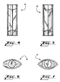
- Fig. 1 shows a perspective view of a product package 10 according to a first aspect of the invention.
- the package 10 includes a sleeve 12 having an upper opening at an upper end and a lower opening at a lower end.
- the sleeve 12 may suitably be fabricated from a sheet of see-through plastic material, such as PVC, APET, PETG, or the like.
- the thickness of the sheet is selected based on a number of factors, including price and strength.
- the sheet should be thick enough to provide structural support, but thin enough to allow the sheet to be flexed and folded, as described herein.
- each end cap 14 and 16 is a rigid body that is shaped to fit closely within its respective opening. As described below, each end cap 14 and 16 is secured in position using a locking mechanism. In the present example, the upper end cap 14 is secured using a releasable locking mechanism, and the lower end cap 16 is secured using a non-releasable locking mechanism.
- the sleeve 12 includes an upper pair of locking tabs 18 that are folded inwards into the interior of the sleeve 12 for securing the upper end cap 14, and a lower pair of locking tabs 20 that are folded inwards into the interior of the sleeve 12 for securing the lower end cap 16.
- the upper end cap 14 includes a pair of channels 22 corresponding in position to the pair of upper locking tabs 18.
- the lower end cap 16 includes a single continuous channel 24 encircling the perimeter of the lower end cap 16.
- the upper end cap 14 is released by twisting the upper end cap 14 within the sleeve 12.
- the lower end cap 16 is not releasable, and cannot be removed without causing damage to the package 10.
- top and bottom end caps 14 and 16 are provided with molded cavities 26 and 28 that are shaped to receive an item to be held in the package 10. It will be appreciated that cavities 26 and 28 may be freely modified to accommodate differently shaped items.
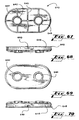
- Figs. 2 through 7 show additional views of the package 10 shown in Fig. 1.
- Figs. 2 and 3 show, respectively, front and rear views of the package.
- Figs. 4 and 5 show left and right side views of the package 10.
- Figs. 6 and 7 show top and bottom views of the package 10.
- Figs. 8 and 9 show elevation views of the upper and lower end caps 14 and 16.
- Each end cap 14 and 16 is a rigid body that may suitably be fabricated, for example, using an injection molding technique. Suitable materials for the end caps include PVC, polypropylene, polyethylene, and polystyrene.
- the upper end cap 14 shown in Fig. 8, as mentioned above, provides a releasable locking mechanism for securing the end cap 14 to the sleeve.
- the releasable locking mechanism includes a pair of rectangular channels 22 on opposite sides of the end cap 14.
- the pair of channels 22 is positioned to receive a corresponding pair of locking tabs 18 extending from the sleeve 12.
- the upper side of each channel 22 is defined by a rim 30 that is dimensioned to be slightly larger than the upper opening of the sleeve 12, and to engage the upper sleeve end to prevent the end cap 14 from being inserted too far into the sleeve opening.
- the lower side of each channel 22 is defined by a ledge 34, which provides a surface for engaging a locking edge of each upper locking tab 18.
- the lower end cap 16 shown in Fig. 9 provides a non-releasable locking mechanism for securing the lower end cap 16 in the lower opening of the sleeve 12.
- the non-releasable locking mechanism includes a single channel 24 encircling the end cap 16.
- the lower side of the channel 24 is defined by a rim 32 that is dimensioned to be larger than the bottom sleeve opening.
- the upper side of the channel 24 is defined by a ledge 36 that provides a surface for engaging a locked edge of each lower locking tab 20 extending from the sleeve 12.
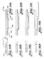
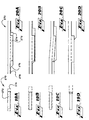
- Fig. 10 shows a plan view of a blank 100 for forming a sleeve according to an aspect of the invention.
- the blank 100 is die cut from a sheet of suitable material, such as PVC, APET, or PETG. If desired, textual or graphic matter may be printed directly onto the blank using a high-speed printing process.
- a series of score lines 102 is fabricated into the blank 100 to divide the blank into a number of panels and tabs.
- the blank 100 includes a first panel 104 and a second panel 106 that are folded towards each other to form the body of the finished sleeve.
- a glue flap 108 extends upward from the first panel 102, opposite the second panel 104, and is used to attach the outside edges of the first and second panels 104 and 106 to each other.
- the releasable locking tabs 110 and 112 are trapezoidal in shape. As discussed below, other shapes may be used for the releasable locking tabs 110 and 112.
- Non-releasable locking tabs 114 and 116 extend from the left side of the first and second panels 104 and 106. According to an aspect of the invention, the non-releasable locking tabs 114 and 116 are rectangular in shape. Each of the locking tabs 110 includes a respective locking edge 120, 122, 124 and 126 that, as described below, engages a ledge in an end cap, such as ledge 156 in end cap 150 illustrated in Figs. 13A-D and described below, to lock the end caps in position in the sleeve ends.
- locking tabs 112 and 116 will line up with locking tabs 110 and 114.
- other orientations for the locking tabs 110, 112, 114 and 116 may also be used without departing from the spirit of the invention.
- the second panel 106 is folded over the first panel 104.
- the partially folded blank 100 is shown in Fig. 11.
- the glue flap 108 is then folded over the second panel 106, and a suitable technique is employed to cause the glue flap 108 to adhere to the second panel 106 at the cross-hatched regions 128 and 130. It will be seen that the bonding of the glue flap 108 to the second panel 106 creates a tube with openings at the left and right of the blank 100.
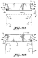
- Fig. 12A shows a plan view of the finished sleeve 100
- Fig. 12B shows a right side view of the sleeve 100.
- the sleeve 100 may be readily popped opened for insertion of the end caps by applying gentle pressure to the sleeve in the direction of the arrows 132 shown in Fig. 12B.
- the sleeve 100 it would be possible for a worker to hold the sleeve 100 in one hand, using the thumb and fingers to apply pressure to the side edges of the sleeve 100. The worker could then pop the sleeve 100 open, and use the other hand to install an end cap into one of the two sleeve openings. Once the first end cap has been installed, the package is relatively stable, and can be stood on end, with the installed end cap acting as a base. Product can then be loaded through the other opening. If necessary, further pressure can be applied to the side edges of the sleeve to open the other opening for loading of the product and installation of the second end cap.
- the above described manual operations may also be performed by machine.
- releasable end caps at both openings of the sleeve, or non-releasable end caps at both openings.
- releasable cap as the top cap or the bottom cap, as desired.
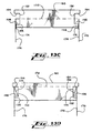
- Figs. 13A-D are cross section diagrams of an exemplary end cap 150 and sleeve end 170 illustrating the operation of a locking mechanism according to an aspect of the invention.
- the drawing of sleeve end 170 includes a broken line 172, which represents the perimeter of the sleeve opening.
- the sleeve end 170 includes a pair of locking tabs 174.
- the locking tabs 174 extend upward from the sleeve 176. Prior to the installation of the end cap 150, the locking tabs 174 are folded into the sleeve opening, towards the inner surface of the sleeve 176. However, because of the resilience of the material used to fabricate the sleeve 176 and locking tabs 174, the locking tabs 174 have a tendency to unfold slightly. The slight unfolding of the locking tabs 174 has been exaggerated in Figs. 13A-D for purposes of illustration. The unfolding of the locking tabs 174 is useful in ensuring a firm locking action.
- the locking cap 150 includes a channel 152 at each side corresponding in position to the locking tabs 174.
- the channels 152 are not drawn to scale.
- a single channel encircles the perimeter of the end cap.
- separate channels are provided, corresponding in position to each of the locking tabs 174.
- the initial locking action is substantially similar.
- the upper boundary of the channel 152 is defined by a rim 154 that, when the end cap 150 is seated in the sleeve end 170, overhangs the sleeve end 170 to prevent the end cap 150 from being further inserted into the sleeve end.
- the channel 152 further includes a ledge 156 that engages a locking edge of each of the locking tabs 174.
- the channel 152 is shown as having a rectangular profile, other channel profiles may also be used. For example, it may be desirable for the ledge to define a more acute angle, or for the channel to be deeper.
- the ledge face 158 is dimensioned and shaped to fit closely within the sleeve.
- Fig. 13B shows the end cap 150 that has been partially inserted into the sleeve end 170.
- the bottom circumference of the end cap 150 urges the locking tabs 174 downward, towards the inner walls of the sleeve 176.
- the locking tabs 174 are pressed against the inner walls of the sleeve 176.
- Fig. 13D when the end cap 150 reaches its final position, the locking tabs 174, because of their resiliency, tend to unfold slightly, causing the locking tabs 174 to open up into the channel 152.
- the slight unfolding of the locking tabs 174 causes the locking edges of the locking tabs 174 to engage the ledge surface 156, thereby preventing the end cap from being pulled upward out of the sleeve opening.
- the end caps have a convexly curved outer perimeter
- the insertion of the end cap into the sleeve causes corresponding curves to form in the sleeve 176 and locking tabs 174. This curvature tends to increase the strength of the locking tabs 174.
- Figs. 14 and 15 show cutaway views of a package 200 according to an aspect of the invention.
- Fig. 14 shows a close-up view of a portion of the package 200 illustrating a single locking tab 202 seated in a channel 204.
- Fig. 15 shows a cutaway of the whole package 200 illustrating a pair of lower locking tabs 202 and a pair of upper locking tabs 206.
- Figs. 16A-D and 17A-D illustrate the operation of a release mechanism 250 according to an aspect of the invention.
- Fig. 16A shows a diagram of a releasable locking tab 252 seated within a rectangular channel 254 in a finished package.
- an upper end cap is shown.
- the upper edge of the channel 254 is defined by the end cap rim
- the lower edge of the channel is defined by a ledge.
- the left and right edges of the channel are defined by surfaces 256 that are substantially continuous with the ledge face.
- the releasable locking tab 252 has a trapezoidal shape.
- an acute vertex 260 is presented to the side edge 258.
- the acute vertex 260 allows the locking tab 252 to ride up the side edge 258 of the channel 254 and onto surface 256, starting with the point of the vertex 260.
- the movement of the locking tab 252 onto surface 256 can be seen in Figs. 17A-D.
- the end cap can be freely twisted within the sleeve opening, even when the end cap does not have a circular perimeter. Twisting the end cap causes a movement of the channel relative to the tab. As described above, this movement causes the locking tab to ride up onto a surface next to the channel, causing the locking tab to become disengaged from the channel and ledge.
- the disengagement of the locking mechanism is illustrated in Figs. 18A and 18B. In Fig. 18A, each locking tab 252 is seated in a channel 254. In Fig. 18B, after the locking cap 262 has been twisted, the locking tabs 252 are no longer in the channels 254. The end cap can now be removed.
- the twist angle required to disengage the end cap 262 from the sleeve 264 can be adjusted by adjusting the dimensions of the channels 254, the locking tabs 252, or both.
- the one-way release mechanism could be accomplished, for example, by using a locking tab having a first side with an acute vertex, and a second side with square vertices. It would be difficult, if not impossible, to twist the end cap off in the direction of the square vertices.
- Figs. 19A-D and Fig. 20A-D illustrate an alternative release mechanism.
- a rectangular locking tab 272 may be used.
- one side of the channel 274 is provided with a ramp 276 leading up to surface 278.
- the locking tab 272 rides up the ramp 276 and onto surface 278 to disengage the locking mechanism.
- only one ramp 276 is provided.
- the locking mechanism can only be released by twisting the end cap in the direction of the ramp 276.
- a second ramp can be added to the other side of the channel 274 to allow the locking mechanism to be released by twisting the end cap in either direction.
- Figs. 21 through 27 show a product package 300 according to another aspect of the invention.
- a releasable end cap 302 is provided at the bottom end of sleeve 304, and a non-releasable cap 306 is provided at the top of the sleeve.
- the end caps 302 and 306 have been shaped to receive a different product, such as a bottle containing lotion or fragrance.
- Figs. 22 and 23 show front and rear views of the package 300.
- Figs. 24 and 25 show left and right side views.
- Figs. 26 and 27 show top and bottom views of the package 300.
- Figs. 28 through 33 show another package 350 according to an aspect of the invention.
- Fig. 28 shows a perspective view of the package 350.
- the channels 352 in the end caps 354 are not rectangular, but instead are angled.
- Figs. 29 and 30 show front and rear views of the package.
- Figs. 31 and 32 show left and right side views, and Fig. 20 shows a top view.
- Fig. 34 shows a perspective view of a cigarette case 400 fabricated according to an aspect of the invention.
- the cigarette case 400 is provided with a sliding top 402 to provide access to cigarettes contained in the case 400.
- the top and bottom caps 404 and 406 may be made releasable, if desired.
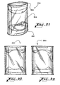
- Fig. 35 shows a perspective view of another product package 450 according to an aspect of the invention.
- the package 450 includes a lid 452 that can be opened and reclosed.
- the package can be used to contain moist towelettes, or other retail item.
- the top and bottom caps 454 and 456 may be made releasable, if desired.
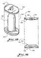
- Fig. 36 shows a perspective view of a product package 500 according to a further aspect of the invention.
- Figs. 37 through 39 show, respectively, side, front, and top views of the package 500.
- the package 500 is designed to hold a liquor bottle 502, or other similarly shaped item.
- the package 500 is fabricated from a sleeve 504, a bottom end cap 520, and a top end cap 540. Similar to the sleeves described above, the sleeve 504 is formed from a sheet of plastic that has been cut to a suitable shape and then folded and glued to form a flat tube with top and bottom openings.
- the sleeve 504 may be fabricated, if desired, from a transparent material.
- Fig. 40 shows an elevation view of the product package.
- the liquor bottle 502 has been omitted from this view.
- Extending from both ends of the sleeve 504 are lower locking tabs 506 and upper locking tabs 508, shown in Fig. 40, for locking the bottom and top end caps 520 and 540 into position.
- the lower locking tabs 506 are rectangular and are seated in a continuous circumferential channel 526.
- the upper locking tabs 508 are trapezoidal and are seated in discrete rectangular channels 550. As discussed above, this geometry creates a non-releasable locking mechanism for the lower end cap 520 and a twist-off, releasable locking mechanism for the upper end cap 540.
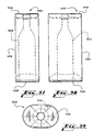
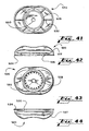
- Figs. 41 through 45 show, respectively, bottom, front, top, rear, and side views of an exemplary embodiment of a bottom end cap 520 suitable for use in the package 500 shown in Figs. 36 through 40.
- Figs. 46 and 47 show, respectively, perspective views of the bottom end cap 520 in upright and inverted positions. It will be seen that the bottom end cap 520 is fabricated as an injection molded shell, with a substantially hollow body.
- the bottom end cap 520 includes a substantially continuous outer circumferential surface 522 that is dimensioned to closely fit within the sleeve 502.
- a rim 524 overhangs the circumferential surface, functioning as a stop to prevent the end cap 520 from being inserted too far into the sleeve 502.
- the end cap 520 further includes a cavity 528 that is shaped to closely receive the bottom of a liquor bottle or a similarly shaped product.
- the cavity 528 includes a central hole 530, which prevents air from getting trapped between the bottom of the liquor bottle and the interior of the cavity 528.
- the central hole 530 also prevents the development of a seal between the bottom of the liquor bottle and the interior of the cavity 528. Such a seal could make it more difficult to remove the liquor bottle from the cavity 528.
- the bottom end cap 506 includes a number of ribs 532 that extend radially between the cavity 528 and an inner wall of the end cap 520.
- the end cap 520 is substantially hollow.
- the ribs provide structural support and rigidity to the bottom end cap 520. This support and rigidity serves a number of functions. First, it facilitates the insertion and seating of the end cap 520 into the sleeve 504. Further, the added rigidity also serves to increase the strength of the locking action.
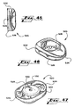
- Figs. 48 through 52 show, respectively, bottom, front, top, rear, and side views of an exemplary embodiment of a top end cap 540 suitable for use in the package 500 shown in Figs. 36 through 40.
- Figs. 53 and 54 show, respectively, perspective views of the top end cap in upright position and inverted positions.
- the top end cap 540 is fabricated as a shell using a suitable injection molding technique.
- the top end cap 540 includes a central cavity 542 that is shaped to fit closely over the top of a liquor bottle or other similarly shaped item.
- the top end cap 540 further includes a series of ribs 544 that extend radially from the central cavity 544 to an inner wall of the top end cap 540.
- the ribs 544 add structural support and rigidity to the end cap.
- the added support and rigidity provided by the ribs 544 serves a number of purposes, including facilitating the insertion of the top end cap 540 into the sleeve 504, strengthening the locking of the top end cap 540, and increasing the overall strength of the finished package.
- the top end cap 540 includes a substantially cylindrical surface 546 that is dimensioned to closely fit within the sleeve 504.
- a rim 548 overhangs the cylindrical surface 546, and serves to prevent the top end cap 540 from being inserted too far into the sleeve 502.
- a series of rectangular channels 548 are formed into the cylindrical surface 546. These rectangular channels 548 engage upper locking tabs 508 protruding from the sleeve 502, similar to the tab arrangements described above. As described, the use of rectangular channels may be used to implement a twist-off feature.
- the package 500 is formed, loaded, and closed, as follows. First, the sleeve 504 is opened, and the bottom end cap 520 is locked into position in the bottom opening of the sleeve by causing locking tabs protruding from the sleeve 504 to engage the channel. The liquor bottle 502 or other item to be packaged is then loaded through the top opening of the sleeve and seated in the receiving cavity 522 in the bottom end cap 520. The top end cap 508 is then locked into the top opening of the sleeve 504, such that the top of the liquor bottle 502 is seated in a receiving opening in the top end cap.
- Fig. 55 shows a perspective view of a package 600 according to a further aspect of the invention.
- Figs. 56 through 58 show, respectively, side, front, and top view of the package 600 shown in Fig. 55.
- the package 600 is designed to hold two liquor bottles 602 and 603 or other items.
- the package may be modified for items 602 and 603 having different shapes and sizes.
- the package 600 includes a sleeve 604, a bottom end cap 620 and a top end cap 640.
- the sleeve 604 is formed from a sheet of plastic that has been cut to a suitable shape and then folded and glued to form a flat tube with top and bottom openings. If desired, the sheet of plastic may be transparent.
- Fig. 59 shows an elevation view of the package 600.
- the liquor bottles 602 and 603 have been omitted from this view.
- the sleeve 606 includes lower locking tabs 606 and upper locking tabs 608 at the respective rims of the top and bottom sleeve openings.
- the lower locking tabs 606 are rectangular and are seated in a continuous circumferential channel 630.
- the upper locking tabs 608 are trapezoidal and are seated in discrete rectangular channels 650. As discussed above, this geometry creates a non-releasable locking mechanism for the lower end cap 620 and a twist-off, releasable locking mechanism for the upper end cap 640.
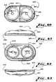
- Figs. 60 through 64 show, respectively, bottom, front, top, rear, and side views of an exemplary embodiment of a bottom end cap 620 suitable for use in the package 600 shown in Figs. 55 through 59.
- Figs. 65 and 66 show, respectively, perspective views of the bottom end cap 620 in upright and inverted positions.
- the bottom end cap 620 is fabricated as an injection molded shell, with a substantially hollow body.
- the bottom end cap 620 includes a pair of cavities 622 and 623 that are shaped to closely receive the bottoms of a pair of liquor bottles 602 and 603 or similarly shaped products. As shown, for example, in Figs. 60 and 62, the cavities 622 and 623 have the same size and shape. However, it would also be possible to use cavities 622 and 623 having different sizes or shapes to package two different items.
- Each cavity 622 and 623 includes a respective central hole 624 and 625, which prevents air from getting trapped between the bottom of each liquor bottle 602 and 603 and the interior of each cavity 622 and 623.
- the central holes 622 and 623 also prevent the development of a seal between the bottom of each liquor bottle 602 and 603 and the interior of the cavities 622 and 623. Such a seal could make it more difficult to remove the liquor bottles 602 and 603 from the cavities 622 and 623.
- the bottom end cap 620 includes a number of ribs 626 that extend radially between the walls of each cavity 622 and 623 and the inner wall of the end cap 620. There is further provided a central rib 627 that extends across the bottom end cap 620, between the two cavities 622 and 623. As mentioned above, the bottom end cap 620 is substantially hollow. The ribs 626 and 627 provide structural support and rigidity to the bottom end cap 620.
- the bottom end cap 620 includes a substantially continuous circumferential surface 626 that is dimensioned to closely fit within the sleeve 602.
- a rim 628 overhangs the circumferential surface 626, which acts as a stop, preventing the end cap from being inserted too far into the sleeve 602.
- Extending around the perimeter of the end cap abutting the rim 628 is a channel 630 that engages lower locking tabs 606 extending from the sleeve 602.
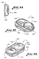
- Figs. 67 through 71 show, respectively, bottom, front, top, rear, and side views of an exemplary embodiment of a top end cap 640 suitable for use in the package 600 shown in Figs. 55 through 59.
- Figs. 72 and 73 show, respectively, perspective views of the top end cap 640 in upright and inverted positions.
- the top end cap 640 is fabricated as a shell using a suitable injection molding technique, and has a substantially hollow body.
- the top end cap 640 includes a pair of central cavities 642 and 643 that are shaped to fit closely over the top of a liquor bottle or other similarly shaped item.
- the top end cap 640 further includes a series of ribs 644 that extend radially from the central cavities 642 and 643 to the inner walls of the top end cap 640.
- a further rib 645 extends across the end cap 640 between the two cavities 642 and 643.
- the ribs 544 add structural support and rigidity to the end cap.
- the top end cap 640 includes a substantially continuous circumferential surface 646 that is dimensioned to closely fit within the sleeve 604.
- a rim 648 overhangs the cylindrical surface 646, and serves to prevent the top end cap 640 from being inserted too far into the sleeve 602.
- a series of rectangular channels 650 are formed into the cylindrical surface 646. These rectangular channels 650 engage upper locking tabs 608 protruding from the sleeve 602, similar to the tab arrangements described above. As described, the use of rectangular channels may be used to implement a twist-off feature.
- the package 600 is formed, loaded, and closed, as follows. First, the sleeve 604 is opened, and the bottom end cap 620 is locked into position in the bottom opening of the sleeve by causing lower locking tabs 606 protruding from the sleeve 604 to engage the channel 650. The liquor bottles 602 and 603 or other item to be packaged are then loaded through the top opening of the sleeve 604 and seated in the respective receiving cavities 622 and 623 in the bottom end cap 620. The top end cap 640 is then locked into the top opening of the sleeve 604, such that the tops of the bottle 602 and 603 are seated in their respective cavities 642 and 643 in the top end cap 640.
Landscapes
- Engineering & Computer Science (AREA)
- Mechanical Engineering (AREA)
- Packages (AREA)
- Closures For Containers (AREA)
- Cartons (AREA)
- Auxiliary Devices For And Details Of Packaging Control (AREA)
Claims (17)
- Verpackung (500), umfassend eine Hülse (504), einschließlich wenigstens eines Endes, das eine Öffnung definiert, wobei die Hülse wenigstens eine Verriegelungslasche (506) enthält, die sich davon erstreckt, wobei die Verriegelungslasche (508) eine Verriegelungskante umfasst, wobei die Verriegelungslasche in die Öffnung nach innen gefaltet ist, wobei die Verpackung ferner eine unbiegsame Endkappe (520) umfasst, die eine im Wesentlichen kontinuierliche Außenseite (522) umfasst, die dimensioniert ist, um schmiegsam in die Öffnung zu passen, wobei die Endkappe ferner Trägerrippen (532) umfasst, die sich radial zwischen einer Kavität (528) und einer Innenwand der Endkappe erstreckt, wobei die Endkappe ferner einen Rand (524) umfasst, der über der Außenseite hängt, so dass dann, wenn die Endkappe in die Öffnung eingebracht wird, der Rand (524) das Ende der Hülse (504) in Eingriff nimmt und die Endkappe (520) daran hindert, weiter in die Öffnung eingebracht zu werden, wobei die Außenseite (526) wenigstens einen Kanal (550) zum Aufnehmen der Verriegelungslasche (508) umfasst, wobei der Kanal (550) eine Leiste aufweist, die die Verriegelungskante der Verriegelungslasche (506) in Eingriff nimmt, um die Endkappe (520) daran zu hindern, aus der Hülsenöffnung entfernt zu werden, wobei der Kanal (550) derart geformt ist, dass die Endkappe (520) freigebbar ist, indem die Endkappe (520) relativ zu der Hülse (504) verdreht wird.
- Verpackung nach Anspruch 1, wobei die Endkappe eine Kavität (542) umfasst, die geformt ist, ein Ende eines zu verpackenden Produkts (502) auf zunehmen.
- Verpackung nach Anspruch 2, wobei die Endkappe (520) Trägerrippen (532) umfasst, die sich radial von der Kavität (520) zu einer Innenwand der Endkappe erstrecken.
- Verpackung nach Anspruch 2, wobei die Verpackung ferner eine zweite Kavität (623) umfasst, die geformt ist, ein zweites Ende eines zu verpackenden Produkts (502) aufzunehmen.
- Verpackung nach Anspruch 4, wobei die Endkappe (520) Trägerrippen (626) umfasst, die sich von jeder Kavität zu einer Innenwand der Endkappe radial erstrecken.
- Verpackung nach Anspruch 5, wobei die Endkappe eine Trägerrippe (627) umfasst, die sich zwischen den zwei Kavitäten über die Endkappe erstreckt.
- Verpackung nach Anspruch 1, wobei jede Verriegelungslasche (608) trapezförmig ist und einen spitzen Vertex hat, der sich auf einer Seitenkante des Kanals (650) bewegt, wenn die Endkappe (620) relativ zu der Hülse (604) verdreht wird, so dass die Endkappe (620) von der Hülse (604) gelöst wird.
- Verpackung nach Anspruch 7, wobei der Kanal (650) wenigstens eine rampenförmige Seitenkante aufweist, so dass dann, wenn die Endkappe (620) relativ zu der Hülse (604) verdreht wird, die Verriegelungslasche sich entlang der rampenförmigen Seitenkante bewegt, so dass die Endkappe (620) von der Hülse (604) losgemacht wird.
- Verpackung nach Anspruch 1, wobei die Hülse (504) ein zweites Ende umfasst, das eine zweite Öffnung definiert, und wobei die Verpackung ferner eine zweite Verriegelungslasche (540) umfasst, die sich von dem zweiten Ende erstreckt und nach innen in die zweite Öffnung gefaltet ist, wobei die zweite Verriegelungslasche (508) eine Verriegelungskante aufweist, wobei die Verpackung außerdem eine zweite Endkappe (540) umfasst, die eine im Wesentlichen kontinuierliche Außenseite (546) aufweist, die dimensioniert ist, um schmiegsam in die zweite Öffnung zu passen, wobei die zweite Endkappe Trägerrippen (532) umfasst, wobei die zweite Endkappe (540) ferner einen Rand (548) umfasst, der über der Außenseite hängt, so dass dann, wenn die zweite Endkappe (540) in die zweite Öffnung eingebracht wird, der Rand (548) das zweite Hülsenende in Eingriff nimmt und verhindert, dass die zweite Endkappe (540) weiter in die zweite Öffnung eingebracht wird, wobei die zweite Endkappe (540) einen Kanal (550) für die Aufnahme der zweiten Verriegelungslasche (508) umfasst, wobei der Kanal (550) eine Leiste aufweist, die die Verriegelungskante der zweiten Verriegelungslasche (508) in Eingriff nimmt, um zu verhindern, dass die zweite Endkappe (540) aus der zweiten Hülsenöffnung entfernt wird.
- Endkappe (540), umfassend Trägerrippen (532), die sich radial zwischen einer Kavität und einer Innenwand der Endkappe erstrecken, sowie eine im Wesentlichen kontinuierliche Außenseite (522), die dimensioniert ist, um schmiegsam in eine Öffnung in einem Ende der Hülse (504) zu passen, wobei die Endkappe ferner einen Rand (524) umfasst, der über der Außenseite hängt, so dass dann, wenn die Endkappe in die Öffnung eingebracht wird, der Rand das Hülsenende in Eingriff nimmt und die Endkappe daran hindert, weiter in die Öffnung eingebracht zu werden, wobei die Außenseite wenigstens einen Kanal (550) für die Aufnahme einer Verriegelungslasche (506) umfasst, die sich von der Hülse erstreckt, wobei der Kanal eine Leiste aufweist, die die Verriegelungskante der Verriegelungslasche in Eingriff nimmt, um die Endkappe daran zu hindern, aus der Hülsenöffnung entfernt zu werden, wobei der Kanal derart geformt ist, dass die Endkappe gelöst werden kann, indem die Endkappe relativ zu der Hülse verdreht wird.
- Endkappe nach Anspruch 10, wobei die Endkappe ferner eine Kavität (528) umfasst, die geformt ist, um ein Ende eines zu verpackenden Produkts aufzunehmen.
- Endkappe nach Anspruch 11, wobei die Endkappe ferner Trägerrippen (532) umfasst, die sich radial von der Kavität zu einer Innenwand der Endkappe erstrecken.
- Endkappe nach Anspruch 11, wobei die Endkappe ferner eine zweite Kavität (623) umfasst, die geformt ist, um ein zweites Ende eines zu verpackenden Produkts aufzunehmen.
- Endkappe nach Anspruch 13, wobei die Endkappe ferner Trägerrippen (532) umfasst, die sich radial von jeder Kavität zu einer Innenwand der Endkappe erstrecken.
- Endkappe nach Anspruch 14, wobei die Endkappe ferner eine Trägerrippe (627) umfasst, die sich über die Endkappe zwischen den zwei Kavitäten erstreckt.
- Verpackung nach Anspruch 15, wobei der Kanal (550) wenigstens eine rampenförmige Seitenkante aufweist, so dass dann, wenn die Endkappe relativ zu der Hülse verdreht wird, die Verriegelungslasche (506) sich entlang der rampenförmigen Seitenkante bewegt, so dass die Endkappe von der Hülse gelöst wird.
- Verfahren zum Herstellen einer Verpackung (500), umfassend:(a) Stanzen und Kerben eines Zuschnitts für eine Hülse (100), um eine erste (104) und eine zweite (106) Wandfläche zu erzeugen, eine Klebeklappe (108), die sich von der ersten Wandfläche erstreckt, sowie Verriegelungslaschen (110, 112), die sich von jeder der Wandflächen erstrecken;(b) Falten der zweiten Wandfläche (106) über die erste Wandfläche (104);(c) Falten der Klebeklappe (108) und Befestigen dieser an die zweite Wandfläche (106), wobei die erste und die zweite Wandfläche eine Hülse (504) ausbilden;(d) Falten der Verriegelungslaschen nach innen in die Hülse;(e) Einbringen einer unbiegsamen Endkappe (520) in ein erstes Ende der Hülse, wobei die Endkappe Trägerrippen (532) umfasst, die sich radial zwischen einer Kavität und einer Innenwand der Endkappe erstrecken, sowie wenigstens einen Kanal (550), der eine Leiste aufweist, die eine Verriegelungskante von jeder Verriegelungslasche in Eingriff nimmt, die sich von dem ersten Ende der Hülse erstrecken, wobei der Kanal derart geformt ist, dass die Endkappe gelöst werden kann, indem die Endkappe relativ zu der Hülse verdreht wird;(f) Laden des Produkts (502) in die Hülse;(g) Einbringen einer zweiten unbiegsamen Endkappe (540) in ein zweites Ende der Hülse, wobei die zweite Endkappe wenigstens einen Kanal umfasst, der eine Leiste aufweist, die eine Verriegelungskante von jeder Verriegelungslasche in Eingriff nimmt, die sich von dem zweiten Ende der Hülse erstrecken, wobei der Kanal derart geformt ist, dass die Endkappe gelöst werden kann, indem die Endkappe relativ zu der Hülse verdreht wird.
Applications Claiming Priority (3)
| Application Number | Priority Date | Filing Date | Title |
|---|---|---|---|
| US39650402P | 2002-07-17 | 2002-07-17 | |
| US396504P | 2002-07-17 | ||
| PCT/US2003/022528 WO2004018301A2 (en) | 2002-07-17 | 2003-07-17 | Product container with locking end cap |
Publications (2)
| Publication Number | Publication Date |
|---|---|
| EP1530543A2 EP1530543A2 (de) | 2005-05-18 |
| EP1530543B1 true EP1530543B1 (de) | 2007-09-12 |
Family
ID=31946694
Family Applications (1)
| Application Number | Title | Priority Date | Filing Date |
|---|---|---|---|
| EP03792974A Expired - Lifetime EP1530543B1 (de) | 2002-07-17 | 2003-07-17 | Produktbehälter mit verriegelbarer endkappe |
Country Status (10)
| Country | Link |
|---|---|
| US (2) | US7644823B2 (de) |
| EP (1) | EP1530543B1 (de) |
| CN (1) | CN100364864C (de) |
| AT (1) | ATE372935T1 (de) |
| AU (1) | AU2003254009A1 (de) |
| BR (1) | BR0312644B1 (de) |
| DE (1) | DE60316302T2 (de) |
| ES (1) | ES2294357T3 (de) |
| MX (1) | MXPA05000693A (de) |
| WO (1) | WO2004018301A2 (de) |
Families Citing this family (93)
| Publication number | Priority date | Publication date | Assignee | Title |
|---|---|---|---|---|
| US20160345631A1 (en) | 2005-07-19 | 2016-12-01 | James Monsees | Portable devices for generating an inhalable vapor |
| US9675109B2 (en) | 2005-07-19 | 2017-06-13 | J. T. International Sa | Method and system for vaporization of a substance |
| US20070163914A1 (en) * | 2005-09-22 | 2007-07-19 | Gehring Debra G | Package closure |
| CA2657814A1 (en) * | 2006-01-20 | 2007-07-26 | Meadwestvaco Corporation | Product packaging with tear strip |
| CA2654259A1 (en) * | 2006-01-20 | 2007-07-26 | Meadwestvaco Corporation | Product packaging systems and methods |
| ATE512069T1 (de) * | 2006-03-23 | 2011-06-15 | Meadwestvaco Corp | Endverschluss für produktbehälter |
| GB2439540A (en) * | 2006-06-28 | 2008-01-02 | Field Group Plc | Tubular container with plug |
| US20080142395A1 (en) * | 2006-12-18 | 2008-06-19 | Printex Packaging Corporation | Package with a locking sleeve |
| US7882953B2 (en) * | 2006-12-18 | 2011-02-08 | Printex Packaging Corporation | Package with a locking sleeve |
| US20090000966A1 (en) * | 2007-06-28 | 2009-01-01 | Baranowski Brad P | Package with Primary and Ancillary Item Compartments |
| USD575149S1 (en) | 2007-06-28 | 2008-08-19 | S.C. Johnson & Son Inc. | Container |
| US8991402B2 (en) | 2007-12-18 | 2015-03-31 | Pax Labs, Inc. | Aerosol devices and methods for inhaling a substance and uses thereof |
| AU325844S (en) * | 2008-10-16 | 2009-04-24 | Pur Water Purification Products | Filter package |
| US20100176020A1 (en) * | 2009-01-13 | 2010-07-15 | Tek Packaging LLC | Packaging with perforated opening strip |
| JP5221409B2 (ja) * | 2009-02-13 | 2013-06-26 | 株式会社コーセー | 包装容器 |
| US20110000811A1 (en) * | 2009-07-02 | 2011-01-06 | Dayan Maurice S | Clamshell package for holding and displaying consumer products |
| US8875893B2 (en) * | 2010-02-05 | 2014-11-04 | Fenwal, Inc. | Medical containers for use in blood collection and processing and medical systems, methods and apparatus for use in blood collection and processing |
| USD669777S1 (en) * | 2010-10-19 | 2012-10-30 | Associated Brands, L.P. | Container |
| GB201100871D0 (en) * | 2011-01-19 | 2011-03-02 | Martinfield Ltd | A brewing device |
| EP2548817A1 (de) * | 2011-07-20 | 2013-01-23 | Huhtamäki Oyj | System, das einen Behälter für eine Flüssigkeit und einen Einsatz umfasst |
| US8695794B2 (en) * | 2011-10-17 | 2014-04-15 | Njoy, Inc. | Electronic cigarette container and method therefor |
| ES1075873Y (es) * | 2011-11-17 | 2012-03-15 | Aragonesa De Desarrollos E Innovaciones S L | Funda protectora para latas de bebida |
| US9096347B2 (en) | 2012-03-20 | 2015-08-04 | Berry Plastics Corporation | Stand-up Package |
| US20130248385A1 (en) | 2012-03-23 | 2013-09-26 | Njoy, Inc. | Electronic cigarette container |
| USD696579S1 (en) | 2012-04-10 | 2013-12-31 | L. Perrigo Company | Product container |
| USD696580S1 (en) | 2012-04-10 | 2013-12-31 | L. Perrigo Company | Product container |
| USD704049S1 (en) | 2012-04-10 | 2014-05-06 | L. Perrigo Company | Product container |
| US10517530B2 (en) | 2012-08-28 | 2019-12-31 | Juul Labs, Inc. | Methods and devices for delivering and monitoring of tobacco, nicotine, or other substances |
| US9145251B2 (en) | 2012-10-26 | 2015-09-29 | Berry Plastics Corporation | Package |
| WO2014134779A1 (zh) * | 2013-03-05 | 2014-09-12 | Liu Qiuming | 防吸嘴盖脱落的电子烟 |
| US10279934B2 (en) | 2013-03-15 | 2019-05-07 | Juul Labs, Inc. | Fillable vaporizer cartridge and method of filling |
| US20140311934A1 (en) * | 2013-04-18 | 2014-10-23 | Robert Dale Beadles | CONTAINEr |
| RU2659887C2 (ru) | 2013-05-06 | 2018-07-04 | Джуул Лэбз, Инк. | Составы на основе солей никотина для аэрозольных устройств и способы их применения |
| WO2014190079A2 (en) | 2013-05-22 | 2014-11-27 | Njoy, Inc. | Compositions, devices, and methods for nicotine aerosol delivery |
| CN105473012B (zh) | 2013-06-14 | 2020-06-19 | 尤尔实验室有限公司 | 电子汽化设备中的具有单独的可汽化材料的多个加热元件 |
| CA2857326C (en) | 2013-07-31 | 2022-04-12 | Op-Hygiene Ip Gmbh | Dispenser shroud |
| CN103407641A (zh) * | 2013-08-28 | 2013-11-27 | 昆山亿达包装有限公司 | 一种瓦楞包装纸盒 |
| USD721577S1 (en) | 2013-11-21 | 2015-01-27 | Njoy, Inc. | Packaging assembly |
| ES3030435T3 (en) | 2013-12-05 | 2025-06-30 | Juul Labs Inc | Nicotine liquid formulations for aerosol devices and methods thereof |
| US9549573B2 (en) | 2013-12-23 | 2017-01-24 | Pax Labs, Inc. | Vaporization device systems and methods |
| US20160366947A1 (en) | 2013-12-23 | 2016-12-22 | James Monsees | Vaporizer apparatus |
| US10058129B2 (en) | 2013-12-23 | 2018-08-28 | Juul Labs, Inc. | Vaporization device systems and methods |
| USD842536S1 (en) | 2016-07-28 | 2019-03-05 | Juul Labs, Inc. | Vaporizer cartridge |
| US10076139B2 (en) | 2013-12-23 | 2018-09-18 | Juul Labs, Inc. | Vaporizer apparatus |
| US10159282B2 (en) | 2013-12-23 | 2018-12-25 | Juul Labs, Inc. | Cartridge for use with a vaporizer device |
| USD825102S1 (en) | 2016-07-28 | 2018-08-07 | Juul Labs, Inc. | Vaporizer device with cartridge |
| CN110638107B (zh) | 2013-12-23 | 2022-11-08 | 尤尔实验室有限公司 | 蒸发装置系统和方法 |
| US9839238B2 (en) | 2014-02-28 | 2017-12-12 | Rai Strategic Holdings, Inc. | Control body for an electronic smoking article |
| US9089166B1 (en) | 2014-05-09 | 2015-07-28 | Njoy, Inc. | Packaging for vaporizing device |
| US9010335B1 (en) | 2014-05-13 | 2015-04-21 | Njoy, Inc. | Mechanisms for vaporizing devices |
| US11478021B2 (en) | 2014-05-16 | 2022-10-25 | Juul Labs, Inc. | Systems and methods for aerosolizing a vaporizable material |
| US11350669B2 (en) | 2014-08-22 | 2022-06-07 | Njoy, Llc | Heating control for vaporizing device |
| AU2015357509B2 (en) | 2014-12-05 | 2021-05-20 | Juul Labs, Inc. | Calibrated dose control |
| US10532872B2 (en) | 2014-12-08 | 2020-01-14 | Berry Plastics Corporation | Package |
| US10251425B2 (en) | 2015-07-06 | 2019-04-09 | Njoy, Llc | Vaporizing device with power component |
| USD809190S1 (en) | 2015-07-13 | 2018-01-30 | Njoy, Llc | Vaporizer |
| US10039323B2 (en) | 2015-07-16 | 2018-08-07 | Njoy, Llc | Vaporizer tank with atomizer |
| USD858868S1 (en) | 2016-02-08 | 2019-09-03 | Juul Labs, Inc. | Vaporizer cartridge |
| WO2017139675A1 (en) | 2016-02-11 | 2017-08-17 | Pax Labs, Inc. | Securely attaching cartridges for vaporizer devices |
| SG11201806793TA (en) | 2016-02-11 | 2018-09-27 | Juul Labs Inc | Fillable vaporizer cartridge and method of filling |
| US10405582B2 (en) | 2016-03-10 | 2019-09-10 | Pax Labs, Inc. | Vaporization device with lip sensing |
| USD849996S1 (en) | 2016-06-16 | 2019-05-28 | Pax Labs, Inc. | Vaporizer cartridge |
| USD836541S1 (en) | 2016-06-23 | 2018-12-25 | Pax Labs, Inc. | Charging device |
| USD851830S1 (en) | 2016-06-23 | 2019-06-18 | Pax Labs, Inc. | Combined vaporizer tamp and pick tool |
| USD848057S1 (en) | 2016-06-23 | 2019-05-07 | Pax Labs, Inc. | Lid for a vaporizer |
| CN117837838A (zh) | 2016-07-28 | 2024-04-09 | 莱施菲公司 | 人造睫毛嫁接物 |
| US11660403B2 (en) | 2016-09-22 | 2023-05-30 | Juul Labs, Inc. | Leak-resistant vaporizer device |
| USD999995S1 (en) * | 2016-12-05 | 2023-09-26 | Lashify, Inc. | Artificial eyelash extension storage cartridge |
| USD955645S1 (en) | 2016-12-05 | 2022-06-21 | Lashify, Inc. | Case for artificial lash extensions |
| USD867668S1 (en) | 2016-12-05 | 2019-11-19 | Lashify, Inc. | Case for artificial lash extensions |
| CA3195110C (en) | 2016-12-20 | 2023-10-31 | Lashify, Inc. | Applicators and cases for artificial lash extensions |
| USD887632S1 (en) | 2017-09-14 | 2020-06-16 | Pax Labs, Inc. | Vaporizer cartridge |
| USD902054S1 (en) | 2019-01-18 | 2020-11-17 | Juul Labs, Inc. | Packaging |
| USD886638S1 (en) | 2018-08-08 | 2020-06-09 | Juul Labs, Inc. | Packaging |
| JP1670874S (de) | 2018-10-19 | 2020-10-26 | ||
| AU2019360273B2 (en) | 2018-10-19 | 2024-03-14 | Lashify, Inc. | Cases for storing lash extensions and methods of use and manufacture thereof |
| USD863679S1 (en) | 2018-10-19 | 2019-10-15 | Lashify, Inc. | False eyelash applicator |
| DK3911202T3 (da) | 2019-01-14 | 2024-10-07 | Lashify Inc | Hylstre, applikatorer til vippeforlængelser og fremgangsmåder til fremstilling og anvendelse deraf |
| USD903192S1 (en) | 2019-02-21 | 2020-11-24 | Juul Labs, Inc. | Vaporizer accessory |
| CN211747241U (zh) | 2019-10-03 | 2020-10-27 | 莱施菲公司 | 人造睫毛装置及睫毛延长装置 |
| USD943160S1 (en) | 2019-11-14 | 2022-02-08 | Juul Labs, Inc. | Vaporizer device |
| USD943158S1 (en) | 2019-11-14 | 2022-02-08 | Juul Labs, Inc. | Vaporizer cartridge |
| USD943161S1 (en) | 2019-11-14 | 2022-02-08 | Juul Labs, Inc. | Vaporizer device |
| USD943159S1 (en) | 2019-11-14 | 2022-02-08 | Juul Labs, Inc. | Component for a vaporizer cartridge |
| USD917093S1 (en) * | 2020-01-15 | 2021-04-20 | 2334271 Ontario Ltd. | Capsule for use in a vaporizer device |
| KR20240041337A (ko) | 2021-08-06 | 2024-03-29 | 래쉬파이 인코포레이티드 | 어플리케이터 및 인조 속눈썹 연장부로부터 인조 모발을 탈착하고 탈착된 인조 모발을 자연 속눈썹에 부착하기 위한 방법 |
| US11998076B2 (en) | 2021-08-06 | 2024-06-04 | Lashify, Inc. | Applicator and method for detaching artificial hairs from an artificial lash extension and affixing the detached artificial hairs at natural lashes |
| US12468139B2 (en) * | 2021-11-07 | 2025-11-11 | Crimson Trace Corporation | Weapon sight packaging |
| USD995914S1 (en) | 2022-07-20 | 2023-08-15 | Lashify, Inc. | Combined tweezer and applicator for artificial lash extensions |
| USD984050S1 (en) | 2022-07-20 | 2023-04-18 | Lashify, Inc. | Combined curler and applicator for natural lashes and artificial lash extensions |
| USD980521S1 (en) | 2022-07-20 | 2023-03-07 | Lashify, Inc. | Artificial lash extension separating comb |
| USD1072354S1 (en) | 2024-01-08 | 2025-04-22 | Lashify, Inc. | Rounded tweezer and applicator for artificial lash extensions |
| US20260065882A1 (en) * | 2024-08-30 | 2026-03-05 | Lee Oskar Levitin | Musical instrument case |
Family Cites Families (27)
| Publication number | Priority date | Publication date | Assignee | Title |
|---|---|---|---|---|
| US2442979A (en) * | 1947-01-23 | 1948-06-08 | Stein A & Co | Belt package |
| US2974825A (en) * | 1959-02-24 | 1961-03-14 | J E Plastics Mfg Corp | Container |
| US2975888A (en) * | 1959-03-26 | 1961-03-21 | Sr Harold G Paynton | Archery package |
| DE1536131A1 (de) * | 1966-09-13 | 1969-12-11 | Landor Walter | Einweg-Behaelter aus Pappe oder anderem biegsamen Werkstoff,mit Verschlussdeckel |
| US3941300A (en) * | 1974-07-19 | 1976-03-02 | Pamark, Inc. | Folded plastic container with snap lid |
| US4051992A (en) * | 1976-04-30 | 1977-10-04 | Bergstein Packaging Trust | Cylindrical display container formed from a flat blank |
| DE2714936A1 (de) * | 1977-04-02 | 1978-10-12 | Theysohn Friedrich Fa | Deckel fuer einen fassartigen behaelter |
| GB2111469B (en) * | 1981-12-17 | 1985-06-26 | Nacanco Ltd | Container lid |
| EP0304387A3 (de) * | 1987-06-24 | 1989-11-23 | Proenvas, S.A. | Verschluss für röhrenförmige Behälter |
| FR2624100B1 (fr) * | 1987-12-02 | 1990-06-01 | Bouche Alain | Boite a verrouillage |
| IT1223648B (it) * | 1988-04-01 | 1990-09-29 | Alplast Snc | Capsula a vite di materiale termoplastico |
| US4802577A (en) * | 1988-07-01 | 1989-02-07 | Leary Dennis E O | Display container for a plurality of belts |
| ES2009480A6 (es) * | 1988-12-23 | 1989-09-16 | Bouche Alain | Caja con enclavamiento. |
| FR2644756A1 (fr) * | 1989-03-21 | 1990-09-28 | Novembal Sa | Boite a couvercle encliquetable |
| JPH03275447A (ja) * | 1990-03-26 | 1991-12-06 | Kazuo Yoshitome | 瓶の包装具 |
| DE9111080U1 (de) * | 1990-09-10 | 1991-10-31 | Stäger & Co. AG, Villmergen | Verpackungsdose |
| JP3122274B2 (ja) * | 1993-01-25 | 2001-01-09 | コニカ株式会社 | パトローネ収納容器 |
| DE9317193U1 (de) * | 1993-11-10 | 1994-01-20 | Lucas Industries P.L.C., Solihull, West Midlands | Kleinladungsträger |
| US5641064A (en) * | 1995-12-29 | 1997-06-24 | Goserud; J. Thomas | Storage container having changeable identifying indicia |
| US5813529A (en) * | 1995-12-29 | 1998-09-29 | Goserud; J. Thomas | Multifunctional cap for a storage container |
| US6230893B1 (en) * | 2000-02-11 | 2001-05-15 | Westvaco Corporation | Unit dose packaging system (udps) having a child resistant locking feature |
| US6971513B2 (en) * | 2000-02-22 | 2005-12-06 | Newfrey Llc | Packaging system for door hardware |
| GB2349143B (en) * | 2000-03-15 | 2001-02-28 | Polestar Taylowe Ltd | A container |
| US6817471B2 (en) * | 2001-10-12 | 2004-11-16 | Brookstone Purchasing, Inc. | Display container |
| US6622867B2 (en) * | 2002-02-19 | 2003-09-23 | Cosmoda Concept Corporation | Package |
| US7000775B2 (en) * | 2002-06-06 | 2006-02-21 | Westvaco Packaging Group, Inc. | Product container with locking end cap |
| US7296729B2 (en) * | 2004-02-06 | 2007-11-20 | Erdie End Caps, Llc | End cap for paper tube |
-
2003
- 2003-07-17 EP EP03792974A patent/EP1530543B1/de not_active Expired - Lifetime
- 2003-07-17 WO PCT/US2003/022528 patent/WO2004018301A2/en not_active Ceased
- 2003-07-17 DE DE60316302T patent/DE60316302T2/de not_active Expired - Lifetime
- 2003-07-17 AU AU2003254009A patent/AU2003254009A1/en not_active Abandoned
- 2003-07-17 US US10/521,349 patent/US7644823B2/en not_active Expired - Lifetime
- 2003-07-17 MX MXPA05000693A patent/MXPA05000693A/es active IP Right Grant
- 2003-07-17 CN CNB038168642A patent/CN100364864C/zh not_active Expired - Lifetime
- 2003-07-17 ES ES03792974T patent/ES2294357T3/es not_active Expired - Lifetime
- 2003-07-17 BR BRPI0312644-7A patent/BR0312644B1/pt active IP Right Grant
- 2003-07-17 AT AT03792974T patent/ATE372935T1/de active
-
2007
- 2007-01-22 US US11/656,157 patent/US7374048B2/en not_active Expired - Fee Related
Also Published As
| Publication number | Publication date |
|---|---|
| US20070163896A1 (en) | 2007-07-19 |
| EP1530543A2 (de) | 2005-05-18 |
| DE60316302D1 (de) | 2007-10-25 |
| ATE372935T1 (de) | 2007-09-15 |
| BR0312644A (pt) | 2005-04-19 |
| ES2294357T3 (es) | 2008-04-01 |
| MXPA05000693A (es) | 2005-04-08 |
| CN1668512A (zh) | 2005-09-14 |
| US7374048B2 (en) | 2008-05-20 |
| BR0312644B1 (pt) | 2013-04-24 |
| AU2003254009A8 (en) | 2004-03-11 |
| WO2004018301A3 (en) | 2004-09-02 |
| WO2004018301A2 (en) | 2004-03-04 |
| DE60316302T2 (de) | 2008-06-05 |
| AU2003254009A1 (en) | 2004-03-11 |
| US20050247578A1 (en) | 2005-11-10 |
| CN100364864C (zh) | 2008-01-30 |
| US7644823B2 (en) | 2010-01-12 |
Similar Documents
| Publication | Publication Date | Title |
|---|---|---|
| EP1530543B1 (de) | Produktbehälter mit verriegelbarer endkappe | |
| EP1509457B1 (de) | Produktbehälter mit verschliessbarer endkappe | |
| US10384843B2 (en) | Pull-tab tamper evident container | |
| US7988034B2 (en) | Dual dispensing container | |
| US20030155271A1 (en) | Package | |
| US8020698B2 (en) | Product packaging systems and methods | |
| EP2318283A1 (de) | Behälter zum anbringen an einem flaschenhals | |
| EP1981367B1 (de) | Produktverpackung mit aufreissstreifen | |
| US7882953B2 (en) | Package with a locking sleeve | |
| EP1534600B1 (de) | Behälter | |
| EP1663796B1 (de) | Montagevorrichtung für flaschenhals | |
| US20080142395A1 (en) | Package with a locking sleeve | |
| HK1075237B (en) | Product container with locking end cap | |
| US20070163914A1 (en) | Package closure | |
| US8668103B2 (en) | Package with a sleeve having a self-initializing locking tab | |
| US20130313150A1 (en) | Packaging | |
| JPS644709Y2 (de) | ||
| HK1092119B (en) | Mounting device for bottle neck | |
| HK1130749A (en) | Product packaging systems and methods |
Legal Events
| Date | Code | Title | Description |
|---|---|---|---|
| PUAI | Public reference made under article 153(3) epc to a published international application that has entered the european phase |
Free format text: ORIGINAL CODE: 0009012 |
|
| 17P | Request for examination filed |
Effective date: 20050114 |
|
| AK | Designated contracting states |
Kind code of ref document: A2 Designated state(s): AT BE BG CH CY CZ DE DK EE ES FI FR GB GR HU IE IT LI LU MC NL PT RO SE SI SK TR |
|
| AX | Request for extension of the european patent |
Extension state: AL LT LV MK |
|
| 17Q | First examination report despatched |
Effective date: 20050509 |
|
| DAX | Request for extension of the european patent (deleted) | ||
| GRAP | Despatch of communication of intention to grant a patent |
Free format text: ORIGINAL CODE: EPIDOSNIGR1 |
|
| RAP1 | Party data changed (applicant data changed or rights of an application transferred) |
Owner name: MEADWESTVACO CORPORATION |
|
| GRAS | Grant fee paid |
Free format text: ORIGINAL CODE: EPIDOSNIGR3 |
|
| GRAA | (expected) grant |
Free format text: ORIGINAL CODE: 0009210 |
|
| RAP1 | Party data changed (applicant data changed or rights of an application transferred) |
Owner name: MEADWESTVACO CORPORATION |
|
| AK | Designated contracting states |
Kind code of ref document: B1 Designated state(s): AT BE BG CH CY CZ DE DK EE ES FI FR GB GR HU IE IT LI LU MC NL PT RO SE SI SK TR |
|
| REG | Reference to a national code |
Ref country code: GB Ref legal event code: FG4D |
|
| REG | Reference to a national code |
Ref country code: CH Ref legal event code: EP |
|
| REF | Corresponds to: |
Ref document number: 60316302 Country of ref document: DE Date of ref document: 20071025 Kind code of ref document: P |
|
| REG | Reference to a national code |
Ref country code: IE Ref legal event code: FG4D |
|
| PG25 | Lapsed in a contracting state [announced via postgrant information from national office to epo] |
Ref country code: FI Free format text: LAPSE BECAUSE OF FAILURE TO SUBMIT A TRANSLATION OF THE DESCRIPTION OR TO PAY THE FEE WITHIN THE PRESCRIBED TIME-LIMIT Effective date: 20070912 |
|
| PG25 | Lapsed in a contracting state [announced via postgrant information from national office to epo] |
Ref country code: CH Free format text: LAPSE BECAUSE OF FAILURE TO SUBMIT A TRANSLATION OF THE DESCRIPTION OR TO PAY THE FEE WITHIN THE PRESCRIBED TIME-LIMIT Effective date: 20070912 Ref country code: LI Free format text: LAPSE BECAUSE OF FAILURE TO SUBMIT A TRANSLATION OF THE DESCRIPTION OR TO PAY THE FEE WITHIN THE PRESCRIBED TIME-LIMIT Effective date: 20070912 |
|
| PG25 | Lapsed in a contracting state [announced via postgrant information from national office to epo] |
Ref country code: BE Free format text: LAPSE BECAUSE OF FAILURE TO SUBMIT A TRANSLATION OF THE DESCRIPTION OR TO PAY THE FEE WITHIN THE PRESCRIBED TIME-LIMIT Effective date: 20070912 |
|
| REG | Reference to a national code |
Ref country code: CH Ref legal event code: PL |
|
| REG | Reference to a national code |
Ref country code: ES Ref legal event code: FG2A Ref document number: 2294357 Country of ref document: ES Kind code of ref document: T3 |
|
| PG25 | Lapsed in a contracting state [announced via postgrant information from national office to epo] |
Ref country code: GR Free format text: LAPSE BECAUSE OF FAILURE TO SUBMIT A TRANSLATION OF THE DESCRIPTION OR TO PAY THE FEE WITHIN THE PRESCRIBED TIME-LIMIT Effective date: 20071213 |
|
| ET | Fr: translation filed | ||
| PG25 | Lapsed in a contracting state [announced via postgrant information from national office to epo] |
Ref country code: SK Free format text: LAPSE BECAUSE OF FAILURE TO SUBMIT A TRANSLATION OF THE DESCRIPTION OR TO PAY THE FEE WITHIN THE PRESCRIBED TIME-LIMIT Effective date: 20070912 Ref country code: PT Free format text: LAPSE BECAUSE OF FAILURE TO SUBMIT A TRANSLATION OF THE DESCRIPTION OR TO PAY THE FEE WITHIN THE PRESCRIBED TIME-LIMIT Effective date: 20080212 Ref country code: CZ Free format text: LAPSE BECAUSE OF FAILURE TO SUBMIT A TRANSLATION OF THE DESCRIPTION OR TO PAY THE FEE WITHIN THE PRESCRIBED TIME-LIMIT Effective date: 20070912 |
|
| PG25 | Lapsed in a contracting state [announced via postgrant information from national office to epo] |
Ref country code: RO Free format text: LAPSE BECAUSE OF FAILURE TO SUBMIT A TRANSLATION OF THE DESCRIPTION OR TO PAY THE FEE WITHIN THE PRESCRIBED TIME-LIMIT Effective date: 20070912 Ref country code: SE Free format text: LAPSE BECAUSE OF FAILURE TO SUBMIT A TRANSLATION OF THE DESCRIPTION OR TO PAY THE FEE WITHIN THE PRESCRIBED TIME-LIMIT Effective date: 20071212 |
|
| PLBE | No opposition filed within time limit |
Free format text: ORIGINAL CODE: 0009261 |
|
| STAA | Information on the status of an ep patent application or granted ep patent |
Free format text: STATUS: NO OPPOSITION FILED WITHIN TIME LIMIT |
|
| PG25 | Lapsed in a contracting state [announced via postgrant information from national office to epo] |
Ref country code: DK Free format text: LAPSE BECAUSE OF FAILURE TO SUBMIT A TRANSLATION OF THE DESCRIPTION OR TO PAY THE FEE WITHIN THE PRESCRIBED TIME-LIMIT Effective date: 20070912 |
|
| 26N | No opposition filed |
Effective date: 20080613 |
|
| PG25 | Lapsed in a contracting state [announced via postgrant information from national office to epo] |
Ref country code: MC Free format text: LAPSE BECAUSE OF NON-PAYMENT OF DUE FEES Effective date: 20080731 |
|
| PG25 | Lapsed in a contracting state [announced via postgrant information from national office to epo] |
Ref country code: EE Free format text: LAPSE BECAUSE OF FAILURE TO SUBMIT A TRANSLATION OF THE DESCRIPTION OR TO PAY THE FEE WITHIN THE PRESCRIBED TIME-LIMIT Effective date: 20070912 |
|
| PG25 | Lapsed in a contracting state [announced via postgrant information from national office to epo] |
Ref country code: SI Free format text: LAPSE BECAUSE OF FAILURE TO SUBMIT A TRANSLATION OF THE DESCRIPTION OR TO PAY THE FEE WITHIN THE PRESCRIBED TIME-LIMIT Effective date: 20070912 |
|
| PG25 | Lapsed in a contracting state [announced via postgrant information from national office to epo] |
Ref country code: CY Free format text: LAPSE BECAUSE OF FAILURE TO SUBMIT A TRANSLATION OF THE DESCRIPTION OR TO PAY THE FEE WITHIN THE PRESCRIBED TIME-LIMIT Effective date: 20070912 Ref country code: IE Free format text: LAPSE BECAUSE OF NON-PAYMENT OF DUE FEES Effective date: 20080717 |
|
| PG25 | Lapsed in a contracting state [announced via postgrant information from national office to epo] |
Ref country code: BG Free format text: LAPSE BECAUSE OF FAILURE TO SUBMIT A TRANSLATION OF THE DESCRIPTION OR TO PAY THE FEE WITHIN THE PRESCRIBED TIME-LIMIT Effective date: 20071212 |
|
| PG25 | Lapsed in a contracting state [announced via postgrant information from national office to epo] |
Ref country code: LU Free format text: LAPSE BECAUSE OF NON-PAYMENT OF DUE FEES Effective date: 20080717 Ref country code: HU Free format text: LAPSE BECAUSE OF FAILURE TO SUBMIT A TRANSLATION OF THE DESCRIPTION OR TO PAY THE FEE WITHIN THE PRESCRIBED TIME-LIMIT Effective date: 20080313 |
|
| PG25 | Lapsed in a contracting state [announced via postgrant information from national office to epo] |
Ref country code: TR Free format text: LAPSE BECAUSE OF FAILURE TO SUBMIT A TRANSLATION OF THE DESCRIPTION OR TO PAY THE FEE WITHIN THE PRESCRIBED TIME-LIMIT Effective date: 20070912 |
|
| PG25 | Lapsed in a contracting state [announced via postgrant information from national office to epo] |
Ref country code: IT Free format text: LAPSE BECAUSE OF NON-PAYMENT OF DUE FEES Effective date: 20080731 |
|
| REG | Reference to a national code |
Ref country code: FR Ref legal event code: TP Owner name: ATLAS AGI HOLDINGS, LLC, US Effective date: 20110909 |
|
| REG | Reference to a national code |
Ref country code: GB Ref legal event code: 732E Free format text: REGISTERED BETWEEN 20111124 AND 20111129 |
|
| REG | Reference to a national code |
Ref country code: DE Ref legal event code: R082 Ref document number: 60316302 Country of ref document: DE Representative=s name: CORINNA VOSSIUS IP GROUP PATENT- UND RECHTSANW, DE Effective date: 20120614 Ref country code: DE Ref legal event code: R081 Ref document number: 60316302 Country of ref document: DE Owner name: ATLAS AGI HOLDINGS, LLC, US Free format text: FORMER OWNER: MEADWESTVACO CORP., GLEN ALLEN, US Effective date: 20120614 Ref country code: DE Ref legal event code: R082 Ref document number: 60316302 Country of ref document: DE Representative=s name: PATRONUS IP PATENT- & RECHTSANWAELTE BERNHARD , DE Effective date: 20120614 Ref country code: DE Ref legal event code: R081 Ref document number: 60316302 Country of ref document: DE Owner name: HIP LIK PACKAGING PRODUCTS FTY. LTD., HK Free format text: FORMER OWNER: MEADWESTVACO CORP., GLEN ALLEN, US Effective date: 20120614 Ref country code: DE Ref legal event code: R081 Ref document number: 60316302 Country of ref document: DE Owner name: HIP LIK PACKAGING PRODUCTS FTY. LTD., HK Free format text: FORMER OWNER: MEADWESTVACO CORP., GLEN ALLEN, VA., US Effective date: 20120614 |
|
| REG | Reference to a national code |
Ref country code: DE Ref legal event code: R082 Ref document number: 60316302 Country of ref document: DE Representative=s name: CORINNA VOSSIUS IP GROUP PATENT- UND RECHTSANW, DE Ref country code: DE Ref legal event code: R082 Ref document number: 60316302 Country of ref document: DE Representative=s name: PATRONUS IP PATENT- & RECHTSANWAELTE BERNHARD , DE |
|
| REG | Reference to a national code |
Ref country code: DE Ref legal event code: R082 Ref document number: 60316302 Country of ref document: DE Representative=s name: PATRONUS IP PATENT- & RECHTSANWAELTE BERNHARD , DE Ref country code: DE Ref legal event code: R082 Ref document number: 60316302 Country of ref document: DE Representative=s name: CORINNA VOSSIUS IP GROUP PATENT- UND RECHTSANW, DE |
|
| REG | Reference to a national code |
Ref country code: DE Ref legal event code: R082 Ref document number: 60316302 Country of ref document: DE Representative=s name: CORINNA VOSSIUS IP GROUP PATENT- UND RECHTSANW, DE |
|
| REG | Reference to a national code |
Ref country code: DE Ref legal event code: R082 Ref document number: 60316302 Country of ref document: DE Representative=s name: CORINNA VOSSIUS IP GROUP PATENT- UND RECHTSANW, DE |
|
| REG | Reference to a national code |
Ref country code: GB Ref legal event code: 732E Free format text: REGISTERED BETWEEN 20140619 AND 20140625 |
|
| REG | Reference to a national code |
Ref country code: DE Ref legal event code: R082 Ref document number: 60316302 Country of ref document: DE Representative=s name: CORINNA VOSSIUS IP GROUP PATENT- UND RECHTSANW, DE Effective date: 20130708 Ref country code: DE Ref legal event code: R082 Ref document number: 60316302 Country of ref document: DE Representative=s name: CORINNA VOSSIUS IP GROUP PATENT- UND RECHTSANW, DE Effective date: 20130721 Ref country code: DE Ref legal event code: R082 Ref document number: 60316302 Country of ref document: DE Representative=s name: CORINNA VOSSIUS IP GROUP PATENT- UND RECHTSANW, DE Effective date: 20140701 Ref country code: DE Ref legal event code: R081 Ref document number: 60316302 Country of ref document: DE Owner name: HIP LIK PACKAGING PRODUCTS FTY. LTD., HK Free format text: FORMER OWNER: ATLAS AGI HOLDINGS, LLC, GRENNWICH, CONN., US Effective date: 20140701 Ref country code: DE Ref legal event code: R082 Ref document number: 60316302 Country of ref document: DE Representative=s name: CORINNA VOSSIUS IP GROUP PATENT- UND RECHTSANW, DE Effective date: 20130819 |
|
| REG | Reference to a national code |
Ref country code: FR Ref legal event code: TP Owner name: HIP LIK PACKAGING PRODUCTS FTY. LTD, HK Effective date: 20140805 |
|
| PGFP | Annual fee paid to national office [announced via postgrant information from national office to epo] |
Ref country code: NL Payment date: 20140726 Year of fee payment: 12 |
|
| PGFP | Annual fee paid to national office [announced via postgrant information from national office to epo] |
Ref country code: AT Payment date: 20150702 Year of fee payment: 13 |
|
| REG | Reference to a national code |
Ref country code: NL Ref legal event code: MM Effective date: 20150801 |
|
| PG25 | Lapsed in a contracting state [announced via postgrant information from national office to epo] |
Ref country code: NL Free format text: LAPSE BECAUSE OF NON-PAYMENT OF DUE FEES Effective date: 20150801 |
|
| REG | Reference to a national code |
Ref country code: FR Ref legal event code: PLFP Year of fee payment: 14 |
|
| REG | Reference to a national code |
Ref country code: AT Ref legal event code: MM01 Ref document number: 372935 Country of ref document: AT Kind code of ref document: T Effective date: 20160717 |
|
| PG25 | Lapsed in a contracting state [announced via postgrant information from national office to epo] |
Ref country code: AT Free format text: LAPSE BECAUSE OF NON-PAYMENT OF DUE FEES Effective date: 20160717 |
|
| REG | Reference to a national code |
Ref country code: FR Ref legal event code: PLFP Year of fee payment: 15 |
|
| REG | Reference to a national code |
Ref country code: FR Ref legal event code: PLFP Year of fee payment: 16 |
|
| PGFP | Annual fee paid to national office [announced via postgrant information from national office to epo] |
Ref country code: GB Payment date: 20220727 Year of fee payment: 20 Ref country code: ES Payment date: 20220801 Year of fee payment: 20 Ref country code: DE Payment date: 20220727 Year of fee payment: 20 |
|
| REG | Reference to a national code |
Ref country code: DE Ref legal event code: R082 Ref document number: 60316302 Country of ref document: DE Representative=s name: GRAPE & SCHWARZENSTEINER, DE |
|
| PGFP | Annual fee paid to national office [announced via postgrant information from national office to epo] |
Ref country code: FR Payment date: 20220725 Year of fee payment: 20 |
|
| REG | Reference to a national code |
Ref country code: DE Ref legal event code: R071 Ref document number: 60316302 Country of ref document: DE |
|
| REG | Reference to a national code |
Ref country code: ES Ref legal event code: FD2A Effective date: 20230726 |
|
| REG | Reference to a national code |
Ref country code: GB Ref legal event code: PE20 Expiry date: 20230716 |
|
| PG25 | Lapsed in a contracting state [announced via postgrant information from national office to epo] |
Ref country code: GB Free format text: LAPSE BECAUSE OF EXPIRATION OF PROTECTION Effective date: 20230716 Ref country code: ES Free format text: LAPSE BECAUSE OF EXPIRATION OF PROTECTION Effective date: 20230718 |
|
| REG | Reference to a national code |
Ref country code: DE Ref legal event code: R082 Ref document number: 60316302 Country of ref document: DE |