EP1529906A2 - Power actuated locking device for covers, lids or similar on a vehicle - Google Patents
Power actuated locking device for covers, lids or similar on a vehicle Download PDFInfo
- Publication number
- EP1529906A2 EP1529906A2 EP04026025A EP04026025A EP1529906A2 EP 1529906 A2 EP1529906 A2 EP 1529906A2 EP 04026025 A EP04026025 A EP 04026025A EP 04026025 A EP04026025 A EP 04026025A EP 1529906 A2 EP1529906 A2 EP 1529906A2
- Authority
- EP
- European Patent Office
- Prior art keywords
- hook
- closure according
- pawl
- power
- catch
- Prior art date
- Legal status (The legal status is an assumption and is not a legal conclusion. Google has not performed a legal analysis and makes no representation as to the accuracy of the status listed.)
- Withdrawn
Links
Images


Classifications
-
- B—PERFORMING OPERATIONS; TRANSPORTING
- B60—VEHICLES IN GENERAL
- B60J—WINDOWS, WINDSCREENS, NON-FIXED ROOFS, DOORS, OR SIMILAR DEVICES FOR VEHICLES; REMOVABLE EXTERNAL PROTECTIVE COVERINGS SPECIALLY ADAPTED FOR VEHICLES
- B60J7/00—Non-fixed roofs; Roofs with movable panels, e.g. rotary sunroofs
- B60J7/185—Locking arrangements
-
- E—FIXED CONSTRUCTIONS
- E05—LOCKS; KEYS; WINDOW OR DOOR FITTINGS; SAFES
- E05B—LOCKS; ACCESSORIES THEREFOR; HANDCUFFS
- E05B81/00—Power-actuated vehicle locks
- E05B81/12—Power-actuated vehicle locks characterised by the function or purpose of the powered actuators
- E05B81/20—Power-actuated vehicle locks characterised by the function or purpose of the powered actuators for assisting final closing or for initiating opening
-
- E—FIXED CONSTRUCTIONS
- E05—LOCKS; KEYS; WINDOW OR DOOR FITTINGS; SAFES
- E05B—LOCKS; ACCESSORIES THEREFOR; HANDCUFFS
- E05B81/00—Power-actuated vehicle locks
- E05B81/54—Electrical circuits
- E05B81/90—Manual override in case of power failure
Definitions
- closures are preferred to convertible top boxes for locking the top compartment lid but can also be used as closures for hoods, flaps or like to be used on vehicles. These closures are between one Opening position, in which it can be brought into engagement with the catch hook closing element, For example, release a closure pin of a closing unit and a closed position, in they lock the locking pin, they pivot.
- closures have the disadvantage that they are in the open position after failure of a drive driving the shutter either do not close the shutter manually or that the shutter closed Position is not secured, so that there is a risk that the closure is self-acting opens.
- This is particularly disadvantageous because, for example, with an open top compartment despite a basic vehicle ready for driving not to continue on a workshop can be started without damaging the top compartment and grown parts to accept.
- the invention has for its object to provide a closure, which is also manually move to a secure closed position.
- a fishing hook usually via a drive element that comes with a functional disc cooperates, i. is directly or indirectly connected to the functional disk, so that a shifting, pivoting, twisting or the like of the drive element between an initial position and an end position pivoting the functional disc and consequently a pivoting of the catch between an open position and a Closed position has the consequence.
- the transmission of the drive movement of the function disc on the fishing hook takes place in the closure according to the invention via a play-related driver connection between catch hook and function disc.
- the catch hook relative to the functional disc, or the functional disc to move relative to the fishing hook, without causing the drive element activated or must be moved.
- the drive movement caused by the drive element is after Bridging the game between the fishing hook and the functional disc continuously transferred to the fishing hook, which is then proportional to the drive element emotional.
- the backlash-type driver connection is designed in such a way that that the fishing hook in trouble-free operating condition in the direction of the closed position of the Fanghakens is connected without play with the function disc, so that a through the Drive initiated opening movement directly, namely without bridging the game on the catch hook can be transmitted.
- a fault then stands, starting from the opening position of the fishing hook when manually pivoting the catch in Direction of the closed position the maximum clearance for the manual pivoting movement to Available.
- the closure according to the invention makes it possible in case of failure of the drive element a manual locking of the hood provided with the closure, top compartment lid or to reach another flap, so that at least one onward journey to a workshop can be made without the fear that the Flap, the top, the top compartment lid or the like springs open, which in particular at higher speeds and a corresponding wind pressure to a Damage to the components may result.
- a manual locking of the closure is independent of the type of damage and the position of the drive at any time.
- the release of the lock can automatically when the drive is activated again when the catch hook in the fully closed position.
- the functional disk can be used directly or indirectly with the Drive element be connected so that, depending on the application and the constructive conditions, the coupling between the functional disk and the drive element can be chosen freely.
- the Function disc is the Function disc, however, hingedly connected to the drive element.
- a direct one Connection of the functional disk according to this embodiment of the invention allows it is to dispense with additional, complicating the construction closing components, so that produce such a trained closure particularly simple and inexpensive leaves.
- a pivotally mounted on an am Closure fixed axis of rotation articulated rocker one hand, the axis of rotation articulated with the drive element and on the other hand the axis of rotation hinged to the Function disc be connected.
- the transmission of the movement of the drive element on the function disc with the interposition of the rocker it allows at a corresponding articulation of the rocker, which then acts as a gear lever, the drive movement to translate into an enlarged pivoting movement of the catch hook or to increase the pulling force.
- the drive of the fishing hook takes place in unchanged manner in the shape shown above, namely by the playful driver connection of the Function disc with the catch hook.
- the playful driver connection between the fishing hook and the functional disk can basically be executed arbitrarily.
- the invention is characterized by a arranged on the fishing hook guide and one arranged on the functional disc and slidable in the guide Guiding element formed, wherein the fishing hook in a limited by the guide Range is manually pivotable.
- the guide element by one of the functional disk in the direction on the fishing hook projecting guide pin and the guide by a corresponding formed the guide pin elongated hole formed on the fishing hook.
- the game between the fishing hook and the functional disk in a simple manner to the required be adapted to constructive conditions in particular the embodiment of Guide and the guide element as a slot and guide pin a special represent simple design that can be produced particularly inexpensive.
- the pawl can basically be placed anywhere on the closure are, if it is ensured that these with the locking projection during manual pivoting of the fishing hook from the open position in the direction of the closed position with a in accordance with the latching projection formed latching mark on the fishing hook into engagement comes.
- the pawl however, in the area of a closing jaw opposite the catch hook arranged rear portion and with the locking projection with one in the rear area the catch hook trained catch mark engageable.
- the pawl is in a biased by the fishing hook pioneering direction.
- This embodiment of the invention ensures in a particularly advantageous manner that the locking projection of the pawl only in the case of a manual operation with a catch mark on the fishing hook into engagement can be brought.
- the Bias biased is the Bias biased so that it also secures the position in which the latching projection and the catch mark on the catch hook are engaged when a manual Operation of the catch hook has taken place.
- the selection of the clamping element is freely selectable.
- the pawl using a hand on a bolt attached to the pawl and on the other hand on one of the closure arranged preloaded bolt arranged spring stands out in particular the fact that it is particularly cost-effective and very easy can assemble. It reliably ensures the desired preload of Pawl in a direction away from the end of the catch hook direction, the arrangement the bolt specifies the biasing direction of the pawl.
- the pawl after reactivation of the drive by completely pivoting the manually locked catch hook in the closed position be unlocked automatically.
- the pawl according to a particularly advantageous embodiment of the invention in a region opposite the locking projection area a projection. This projection makes it possible to pivot the pawl against the latching direction, wherein the catch mark and the locking projection are disengaged and the fishing hook is released. This may be necessary in particular when reactivating the drive is required to open the shutter, which otherwise only with a considerable effort or special tool is possible.
- a pivoting of the pawl in a position in which this in the case of a manual Lock with its locking projection with the catch mark on the fishing hook into engagement can be brought, in principle, with any design means, eg. With additional Control levers or discs done.
- the pawl of the invention is arranged such that it in the open position with the rocker and / or is engaged with the functional disk and in the direction of the Fishing hook is pivoted, in particular rests on this.
- the position in which rests the pawl with the locking projection on the back of the fishing hook is a position in which can be ensured very reliable that in the case of a manual operation of the fishing hook this locks with the pawl.
- the rocker and / or the functional disk in the open position with a protruding spring element of the fishing hook, in particular a leaf spring into engagement.
- the fishing hook is in Direction biased to the opening position.
- a torsion spring biases the fishing hook towards the open position.
- the bias towards the open position ensures that the fishing hook at a controlled by the drive element pivotal movement between the open position and the closed position directly a pivoting movement proportional to the movement the drive element performs, as the game between the functional disc and the Fishing hook extends in the opposite direction.
- the bias by means of the above illustrated torsion spring represents a particularly cost-effective variant, wherein the already existing guide pin used on one side as a support element for the torsion spring can be, so that according to this embodiment of the invention, only an additional bolt must be arranged on the fishing hook.
- Due to the special features of the closure according to the invention can in principle all power-generating drive elements are used, which are able to Catch between the open position and the closed position to move, so feathers, Pneumatic cylinders, hydraulic cylinders, electrically operated mother spindle units or like. It only depends on that of the force-generating drive element applied closing movement can be reversed.
- a push rod provided.
- the push rod can, if necessary, with interposition a joint are placed directly on the functional disc or the rocker, so that can be dispensed with additional coupling elements, whereby the manufacturing cost the closure can be lowered in a complementary manner.
- a limit switch to Display of the opening and / or closing position provided.
- a limit switch which after a particularly advantageous embodiment of the invention with the drive element is coupled, ensures that after reaching the opening position or closing position this are displayed and the drive is turned off accordingly, so that damage the closure can be effectively prevented.
- End stops are arranged, which in any case limit the pivoting movement of the catch to damage the closure or possibly To be able to reliably exclude attachments in a complementary manner.
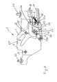
- closures 2 shown here When using the closures 2 shown here for locking from here illustrated top boxes, covering or the like, these are usually installed in pairs in a closing unit 1 shown in Figure 1, which on the vehicle on a hood, top compartment lid, top compartment frame, flap or the like can be arranged.
- the clamping unit 1 has a centrally arranged Central drive 21, which is arranged via a drive linkage 11 with the end to this Closures 2 is connected so that a in the closure 2 pivotally mounted fishing hook 4 pivoted between an open position and a closed position can be.
- the closure 2 shown in Figures 1 to 5 consists of a housing, the formed opposite sheet metal discs 3, which riveted using Distance bolts 19 are assembled into one unit.
- the fishing hook 4 is connected to a centrally disposed bearing pin 12 between the Close position ( Figure 2) and the open position ( Figure 3) pivotally mounted. At his front end, the fishing hook 4 a closing jaw 25 for engagement with a not shown here locking pin. That the closing mouth 25 opposite End has a latch 27.
- a guide pin 14 is arranged, which in the direction of projects the fishing hook 4 and projects through a slot 7 in the fishing hook 4, so that the pivoting range of the fishing hook 4 depending on the position of the Guide pin 14 and the slot 7 determined.
- rocker 5 and functional disk 6 is in the region of the rear end of the fishing hook 4 a pawl 10th pivotable about its central region on a bearing pin arranged on the housing 18 arranged.
- top, top compartment frame or the like For fastening the closure to a convertible top compartment, top, top compartment frame or the like has these flanges 23, which are for receiving screws 20 are formed.
- the closure parts 4, 5, 6, io by moving of the drive linkage 11 between the closed position shown in Figure 2 and the in Figure 3 shown opening position moves.
- the drive linkage 11 is thereby from Central drive 21 seen from the direction of the shutter 2, whereby the Rocker 5 is pivoted about the pin 17.
- the rocker 5 and the functional disk 6 Due to the articulated connection the rocker 5 and the functional disk 6 is the pivoting of the rocker fifth also the functional disk 6 is pivoted, namely about the bearing pin 12, wherein also the fixedly connected to the functional disk 6 guide pin 14 to the Bearing pin 12 is pivoted.
- the fishing hook 4 is doing by depressing the top or the top compartment lid also depressed. Due to the connection of the fishing hook 4 to the Function disc 6 limited over the guided in the slot 7 guide pin 14 the movement of the closure parts 4, 5, 6 in the manual operation alone on the fishing hook 4, which can be pivoted as far as the guide pin 14 at the closing mouth 25 opposite end of the slot 7 to the plant comes.
- a arranged on the closures 2 limit switch 24 is used for detecting and indicating the reaching of the opening and closing position of the catch hook 4.
Abstract
Description
Die Erfindung betrifft ein kraftunterstützten Verschluß für Verdecke, Klappen oder dergleichen an Fahrzeugen mit
- einem zwischen einer Öffnungslage und einer Schließlage bewegbaren, schwenkbar gelagerten Fanghaken und
- einem kraftspendenden Antriebselement, zum Antrieb des Fanghakens.
- a movable between an open position and a closed position, pivotally mounted fishing hooks and
- a power-generating drive element, for driving the catch hook.
Derartige Verschlüsse werden bevorzugt an Verdeckkästen zur Verriegelung der Verdeckkästendeckel eingesetzt, können jedoch auch als Verschlüsse für Verdecke, Klappen oder dergleichen an Fahrzeugen eingesetzt werden. Diese Verschlüsse sind zwischen einer Öffnungslage, in der sie einen mit dem Fanghaken in Eingriff bringbares Schließelement, bspw. einen Verschlußzapfen einer Verschließeinheit freigeben und einer Schließlage, in der sie den Verschlußzapfen arretieren, verschwenkbar.Such closures are preferred to convertible top boxes for locking the top compartment lid but can also be used as closures for hoods, flaps or like to be used on vehicles. These closures are between one Opening position, in which it can be brought into engagement with the catch hook closing element, For example, release a closure pin of a closing unit and a closed position, in they lock the locking pin, they pivot.
Bekannte Ausführungsformen derartiger Verschlüsse weisen jedoch den Nachteil auf, daß sie sich nach Ausfall eines den Verschluß antreibenden Antriebselements in der Öffnungslage des Verschlusses entweder nicht manuell schließen lassen oder daß die geschlossene Position nicht gesichert ist, so daß die Gefahr besteht, daß der Verschluß sich selbsttätig öffnet. Dieses ist insbesondere deshalb nachteilig, weil bspw. mit einem geöffneten Verdeckkasten trotz eines grundsätzlichen fahrbereiten Fahrzeugs nicht die Weiterfahrt zu einer Werkstatt angetreten werden kann, ohne eine Beschädigung des Verdeckkastens und angebauter Teile in Kauf nehmen zu müssen.However, known embodiments of such closures have the disadvantage that they are in the open position after failure of a drive driving the shutter either do not close the shutter manually or that the shutter closed Position is not secured, so that there is a risk that the closure is self-acting opens. This is particularly disadvantageous because, for example, with an open top compartment despite a basic vehicle ready for driving not to continue on a workshop can be started without damaging the top compartment and grown parts to accept.
Der Erfindung liegt die Aufgabe zugrunde, einen Verschluß bereitzustellen, der sich auch manuell in eine gesicherte Schließlage bewegen läßt.The invention has for its object to provide a closure, which is also manually move to a secure closed position.
Die Erfindung löst die Aufgabe durch einen Verschluß gemäß Anspruch 1. Vorteilhafte Weiterbildungen der Erfindung sind in den abhängigen Ansprüchen angegeben.The invention solves the problem by a closure according to claim 1. Advantageous Further developments of the invention are specified in the dependent claims.
Bei einem Verschluß gemäß der Erfindung erfolgt die Steuerung des Bewegungsablaufs eines Fanghakens in der Regel über ein Antriebselement, das mit einer Funktionsscheibe zusammenwirkt, d.h. direkt oder indirekt mit der Funktionsscheibe verbunden ist, so daß ein Verschieben, Verschwenken, Verdrehen oder dergleichen des Antriebselements zwischen einer Anfangsstellung und einer Endstellung ein Verschwenken der Funktionsscheibe und folglich ein Verschwenken des Fanghakens zwischen einer Öffnungslage und einer Schließlage zur Folge hat.In a closure according to the invention, the control of the movement sequence takes place a fishing hook usually via a drive element that comes with a functional disc cooperates, i. is directly or indirectly connected to the functional disk, so that a shifting, pivoting, twisting or the like of the drive element between an initial position and an end position pivoting the functional disc and consequently a pivoting of the catch between an open position and a Closed position has the consequence.
Die Übertragung der Antriebsbewegung von der Funktionsscheibe auf den Fanghaken erfolgt bei dem erfindungsgemäßen Verschluß über eine spielbehaftete Mitnehmerverbindung zwischen Fanghaken und Funktionsscheibe. In Abhängigkeit von der Größe des Spiels ist es möglich, den Fanghaken relativ zur Funktionsscheibe, bzw. die Funktionsscheibe relativ zum Fanghaken zu bewegen, ohne daß dabei das Antriebselement aktiviert bzw. verschoben werden muß.The transmission of the drive movement of the function disc on the fishing hook takes place in the closure according to the invention via a play-related driver connection between catch hook and function disc. Depending on the size of the game it is possible, the catch hook relative to the functional disc, or the functional disc to move relative to the fishing hook, without causing the drive element activated or must be moved.
Grundsätzlich wird die durch das Antriebselement hervorgerufene Antriebsbewegung nach Überbrückung des Spiels zwischen dem Fanghaken und der Funktionsscheibe kontinuierlich auf den Fanghaken übertragen, der sich dann proportional zum Antriebselement bewegt.Basically, the drive movement caused by the drive element is after Bridging the game between the fishing hook and the functional disc continuously transferred to the fishing hook, which is then proportional to the drive element emotional.
Vorteilhafterweise ist die spielbehaftete Mitnehmerverbindung jedoch derart ausgestaltet, daß der Fanghaken im störungsfreien Betriebszustand in Richtung der Schließlage des Fanghakens spielfrei mit der Funktionsscheibe verbunden ist, so daß eine durch den Antrieb eingeleitete Öffnungsbewegung direkt, nämlich ohne Überbrückung des Spiels auf den Fanghaken übertragen werden kann. Im Falle einer Störung steht dann, ausgehend von der Öffnungslage des Fanghakens, beim manuellen Verschwenken des Fanghakens in Richtung der Schließlage das maximale Spiel für die manuelle Schwenkbewegung zur Verfügung.Advantageously, however, the backlash-type driver connection is designed in such a way that that the fishing hook in trouble-free operating condition in the direction of the closed position of the Fanghakens is connected without play with the function disc, so that a through the Drive initiated opening movement directly, namely without bridging the game on the catch hook can be transmitted. In case of a fault then stands, starting from the opening position of the fishing hook when manually pivoting the catch in Direction of the closed position the maximum clearance for the manual pivoting movement to Available.
Im wesentlichen nach vollständiger Beendigung der durch das Spiel möglichen manuellen Schwenkbewegung des Fanghakens, wobei die Funktionsscheibe in ihrer Stellung verharrt, kommt ein Rastvorsprung einer Sperrklinke dann mit einer entsprechend ausgebildeten Rastmarke an dem Fanghaken in Eingriff und verriegelt die durch manuelles Verschwenken erreichte Verschlußposition, in der ein mit dem Verschluß zusammenwirkendes Schließelement, bspw. ein Verschlußzapfen sicher an dem Fanghaken arretiert ist.In essence, after the completion of the possible by the game manual Pivoting movement of the catch hook, wherein the functional disk remains in position, then comes a locking projection of a pawl then with a trained accordingly Locking mark on the fishing hook engaged and locked by manual pivoting reached closure position in which cooperates with the closure Closing element, for example. A locking pin is securely locked to the fishing hook.
Um im regulären Betrieb, d.h. im störungsfreien Betrieb, bei dem der Fanghaken alleine durch das Antriebselement zwischen der Öffnungslage und der Schließlage verschwenkt wird, Störungen zu vermeiden und einen reibungslosen Betrieb zu gewährleisten, ist die Sperrklinke so angeordnet, daß der Rastvorsprung während des regulären Betriebs nicht mit der Rastmarke am Fanghaken in Eingriff kommt.In regular operation, i. in trouble-free operation, where the fishing hook alone pivoted by the drive element between the open position and the closed position is to avoid interference and to ensure smooth operation is the Pawl arranged so that the locking projection during normal operation is not with the catch mark on the fishing hook engages.
Der erfindungsgemäße Verschluß ermöglicht es, bei einem Ausfall des Antriebselements eine manuelle Verriegelung des mit dem Verschluß versehenen Verdecks, Verdeckkastendeckel oder einer sonstigen Klappe zu erreichen, so daß zumindest eine Weiterfahrt zu einer Werkstatt vorgenommen werden kann, ohne daß befürchtet werden muß, daß die Klappe, das Verdeck, der Verdeckkastendeckel oder dergleichen aufspringt, was insbesondere bei höheren Fahrtgeschwindigkeiten und einem entsprechenden Winddruck zu einer Beschädigung der Bauteile führen kann.The closure according to the invention makes it possible in case of failure of the drive element a manual locking of the hood provided with the closure, top compartment lid or to reach another flap, so that at least one onward journey to a workshop can be made without the fear that the Flap, the top, the top compartment lid or the like springs open, which in particular at higher speeds and a corresponding wind pressure to a Damage to the components may result.
Eine manuelle Verriegelung des Verschlusses ist dabei unabhängig von der Art der Beschädigung und der Stellung des Antriebs jederzeit möglich. Das Lösen der Verriegelung kann automatisch bei wieder aktiviertem Antrieb erfolgen, wenn sich der Fanghaken in der vollständigen Schließstellung befindet.A manual locking of the closure is independent of the type of damage and the position of the drive at any time. The release of the lock can automatically when the drive is activated again when the catch hook in the fully closed position.
Wie bereits oben dargestellt kann die Funktionsscheibe direkt oder indirekt mit dem Antriebselement verbunden sein, so daß in Abhängigkeit vom Einsatzzweck und den konstruktiven Bedingungen die Kopplung zwischen Funktionsscheibe und Antriebselement frei gewählt werden kann. Nach einer vorteilhaften Weiterbildung der Erfindung ist die Funktionsscheibe jedoch gelenkig mit dem Antriebselement verbunden. Eine direkte Anbindung der Funktionsscheibe gemäß dieser Weiterbildung der Erfindung ermöglicht es, auf zusätzliche, den Aufbau verkomplizierende Schließbauteile zu verzichten, so daß sich ein derartig weitergebildeter Verschluß besonders einfach und kostengünstig herstellen läßt.As already shown above, the functional disk can be used directly or indirectly with the Drive element be connected so that, depending on the application and the constructive conditions, the coupling between the functional disk and the drive element can be chosen freely. According to an advantageous embodiment of the invention is the Function disc, however, hingedly connected to the drive element. A direct one Connection of the functional disk according to this embodiment of the invention allows it is to dispense with additional, complicating the construction closing components, so that produce such a trained closure particularly simple and inexpensive leaves.
Nach einer weiteren Ausführungsform der Erfindung kann eine schwenkbar an einer am Verschluß ortsfesten Drehachse gelenkig gelagerte Schwinge einerseits der Drehachse gelenkig mit dem Antriebselement und andererseits die Drehachse gelenkig mit der Funktionsscheibe verbunden sein. Die Übertragung der Bewegung des Antriebselements auf die Funktionsscheibe unter Zwischenschaltung der Schwinge erlaubt es bei einer entsprechenden Anlenkung der Schwinge, die dann als Getriebehebel fungiert, die Antriebsbewegung in eine vergrößerte Schwenkbewegung des Fanghakens zu übersetzen oder die Zuziehkraft zu steigern. Der Antrieb des Fanghakens erfolgt in unveränderter Weise in der oben dargestellten Form, nämlich durch die spielbehaftete Mitnehmerverbindung der Funktionsscheibe mit dem Fanghaken.According to a further embodiment of the invention, a pivotally mounted on an am Closure fixed axis of rotation articulated rocker one hand, the axis of rotation articulated with the drive element and on the other hand the axis of rotation hinged to the Function disc be connected. The transmission of the movement of the drive element on the function disc with the interposition of the rocker it allows at a corresponding articulation of the rocker, which then acts as a gear lever, the drive movement to translate into an enlarged pivoting movement of the catch hook or to increase the pulling force. The drive of the fishing hook takes place in unchanged manner in the shape shown above, namely by the playful driver connection of the Function disc with the catch hook.
Die spielbehaftete Mitnehmerverbindung zwischen dem Fanghaken und der Funktionsscheibe kann grundsätzlich beliebig ausgeführt sein. Nach einer vorteilhaften Weiterbildung der Erfindung ist diese jedoch durch eine an dem Fanghaken angeordnete Führung sowie einem an der Funktionsscheibe angeordneten und in der Führung verschiebbaren Führungselement gebildet, wobei der Fanghaken in einem durch die Führung begrenzten Bereich manuell verschwenkbar ist. Nach einer besonders vorteilhaften Weiterbildung der Erfindung ist dabei das Führungselement durch eine von der Funktionsscheibe in Richtung auf den Fanghaken vorstehenden Führungsbolzen und die Führung durch ein entsprechend dem Führungsbolzen ausgebildetes Langloch am Fanghaken gebildet.The playful driver connection between the fishing hook and the functional disk can basically be executed arbitrarily. After an advantageous development However, the invention is characterized by a arranged on the fishing hook guide and one arranged on the functional disc and slidable in the guide Guiding element formed, wherein the fishing hook in a limited by the guide Range is manually pivotable. After a particularly advantageous development of The invention is the guide element by one of the functional disk in the direction on the fishing hook projecting guide pin and the guide by a corresponding formed the guide pin elongated hole formed on the fishing hook.
In Abhängigkeit von den Abmessungen der Führung, insbesondere der Abmessungen des Langlochs und des Führungselements, insbesondere des Führungsbolzens, kann das Spiel zwischen dem Fanghaken und der Funktionsscheibe in einfacher Weise an die geforderten konstruktiven Bedingungen angepaßt werden, wobei insbesondere die Ausgestaltung der Führung und des Führungselements als Langloch und Führungsbolzen eine besonders einfache Ausgestaltung darstellen, die sich besonders kostengünstig herstellen läßt.Depending on the dimensions of the guide, in particular the dimensions of the Long hole and the guide element, in particular the guide pin, the game between the fishing hook and the functional disk in a simple manner to the required be adapted to constructive conditions, in particular the embodiment of Guide and the guide element as a slot and guide pin a special represent simple design that can be produced particularly inexpensive.
Im Falle der oben dargestellten direkten Verbindung des Antriebselements an die Funktionsscheibe ist nach einer besonders vorteilhaften Weiterbildung des erfindungsgemäßen Verschlusses die Funktionsscheibe einerseits der gelenkigen Lagerung mit dem Antriebselement verbunden und weist andererseits ihrer gelenkigen Lagerung das Führungselement auf. Diese Anordnung der Funktionsscheibe bei direkter Anlenkung an das Antriebselement erlaubt es, den Verschluß insgesamt besonders kompakt auszuführen, insbesondere da nach einer besonders vorteilhaften Weiterbildung der Erfindung die Funktionsscheibe auch auf der gleichen Schwenkachse des Fanghakens angeordnet sein kann. Zudem kann über den frei wählbaren Abstand der Anlenkung der Funktionsscheibe an das Antriebselement und den Abstand zum Führungselement die übertragbare Kraft frei eingestellt und an die vorgegebenen Anforderungen angepaßt werden.In the case of the above-described direct connection of the drive element to the functional disk is according to a particularly advantageous embodiment of the invention Close the functional disc on the one hand the articulated mounting with the drive element connected and on the other hand, its articulated bearing the guide element on. This arrangement of the functional disk with direct linkage to the drive element allows the closure to be made particularly compact overall, in particular because according to a particularly advantageous embodiment of the invention, the functional disk can also be arranged on the same pivot axis of the fishing hook. moreover can over the freely selectable distance of the articulation of the functional disk to the drive element and set the distance to the guide element, the transferable force freely and adapted to the given requirements.
Auch die Sperrklinke kann grundsätzlich an beliebiger Stelle am Verschluß angeordnet werden, sofern gewährleistet ist, daß diese mit dem Rastvorsprung beim manuellen Verschwenken des Fanghakens aus der Öffnungslage in Richtung der Schließlage mit einer entsprechend dem Rastvorsprung ausgebildeten Rastmarke am Fanghaken in Eingriff kommt. Nach einer besonders vorteilhaften Weiterbildung der Erfindung ist die Sperrklinke jedoch im Bereich eines einem Schließmaul des Fanghakens gegenüberliegenden hinteren Bereichs angeordnet und mit dem Rastvorsprung mit einem im hinteren Bereich des Fanghakens ausgebildeten Rastmarke in Eingriff bringbar.The pawl can basically be placed anywhere on the closure are, if it is ensured that these with the locking projection during manual pivoting of the fishing hook from the open position in the direction of the closed position with a in accordance with the latching projection formed latching mark on the fishing hook into engagement comes. According to a particularly advantageous embodiment of the invention, the pawl however, in the area of a closing jaw opposite the catch hook arranged rear portion and with the locking projection with one in the rear area the catch hook trained catch mark engageable.
Insbesondere bei einem sich vom Schließmaul weg erstreckenden Antriebselement erlaubt diese Weiterbildung der Erfindung die platzsparende Anordnung der Sperrklinke zwischen dem hinteren Ende des Fanghakens und dem Antriebselement, so daß die Größe des Verschlusses in ergänzender Weise reduziert werden kann. Zudem kann bei dieser Anordnung der Sperrklinke der Fanghaken sowie das Schließmaul im wesentlichen frei gestaltet werden, ohne daß dieser bzw. im Kontaktbereich mit einem Anschlußzapfen an eine andernfalls vorhandene Sperrklinke angepaßt werden muß.In particular, allowed at a wegmaul away from the closing mouth drive element This development of the invention, the space-saving arrangement of the pawl between the rear end of the catch and the drive element, so that the size of the Closure can be reduced in a complementary manner. In addition, with this arrangement the pawl of the fishing hook and the closing jaw designed essentially free be without this or in the contact area with a connecting pin to a otherwise existing pawl must be adjusted.
Nach einer weiteren vorteilhaften Ausgestaltung der Erfindung ist die Sperrklinke in eine von dem Fanghaken wegweisende Richtung vorgespannt. Diese Ausgestaltung der Erfindung gewährleistet in besonders vorteilhafter Weise, daß der Rastvorsprung der Sperrklinke nur im Falle einer manuellen Betätigung mit einer Rastmarke am Fanghaken in Eingriff bringbar ist. Nach einer besonders vorteilhaften Weiterbildung der Erfindung ist dabei die Vorspannung so ausgerichtet, daß diese auch die Position sichert, in der sich der Rastvorsprung und die Rastmarke am Fanghaken in Eingriff befinden, wenn eine manuelle Betätigung des Fanghakens stattgefunden hat.According to a further advantageous embodiment of the invention, the pawl is in a biased by the fishing hook pioneering direction. This embodiment of the invention ensures in a particularly advantageous manner that the locking projection of the pawl only in the case of a manual operation with a catch mark on the fishing hook into engagement can be brought. According to a particularly advantageous embodiment of the invention is the Bias biased so that it also secures the position in which the latching projection and the catch mark on the catch hook are engaged when a manual Operation of the catch hook has taken place.
Die Auswahl des Spannelements ist dabei frei wählbar. Nach einer besonders vorteilhaften Weiterbildung der Erfindung ist die Sperrklinke jedoch unter Verwendung einer einerseits an einem an der Sperrklinke befestigten Bolzen und andererseits an einem am Verschluß angeordneten Bolzen gelagerten Spiralfeder vorgespannt. Die Spiralfeder zeichnet sich insbesondere dadurch aus, daß sie besonders kostengünstig ist und sich besonders leicht montieren läßt. Dabei gewährleistet sie zuverlässig die gewünschte Vorspannung der Sperrklinke in eine vom Ende des Fanghakens weg gerichtete Richtung, wobei die Anordnung der Bolzen die Vorspannrichtung der Sperrklinke vorgibt.The selection of the clamping element is freely selectable. After a particularly advantageous Development of the invention, however, the pawl using a hand on a bolt attached to the pawl and on the other hand on one of the closure arranged preloaded bolt arranged spring. The spiral spring stands out in particular the fact that it is particularly cost-effective and very easy can assemble. It reliably ensures the desired preload of Pawl in a direction away from the end of the catch hook direction, the arrangement the bolt specifies the biasing direction of the pawl.
Wie bereits eingangs dargestellt, kann die Sperrklinke nach Reaktivierung des Antriebs durch vollständiges Verschwenken des manuell verriegelten Fanghakens in die Schließlage automatisch entriegelt werden. Um jedoch auch eine manuelle Entriegelung zu ermöglichen, weist die Sperrklinke nach einer besonders vorteilhaften Weiterbildung der Erfindung in einem dem Rastvorsprung gegenüberliegenden Bereich einen Vorsprung auf. Dieser Vorsprung ermöglicht es, die Sperrklinke entgegen der Rastrichtung zu Verschwenken, wobei die Rastmarke und der Rastvorsprung außer Eingriff kommen und der Fanghaken freigegeben wird. Dies kann insbesondere dann erforderlich sein, wenn es zur Reaktivierung des Antriebs erforderlich ist, den Verschluß zu öffnen, was ansonsten nur mit einem erheblichen Aufwand oder Spezialwerkzeug möglich ist.As already mentioned, the pawl after reactivation of the drive by completely pivoting the manually locked catch hook in the closed position be unlocked automatically. However, to allow manual unlocking, has the pawl according to a particularly advantageous embodiment of the invention in a region opposite the locking projection area a projection. This projection makes it possible to pivot the pawl against the latching direction, wherein the catch mark and the locking projection are disengaged and the fishing hook is released. This may be necessary in particular when reactivating the drive is required to open the shutter, which otherwise only with a considerable effort or special tool is possible.
Ein Verschwenken der Sperrklinke in eine Position, in der diese im Falle einer manuellen Verriegelung mit ihrem Rastvorsprung mit der Rastmarke am Fanghaken in Eingriff bringbar ist, kann grundsätzlich mit beliebigen konstruktiven Mitteln, bspw. mit zusätzlichen Steuerungshebeln oder -scheiben erfolgen. Nach einer vorteilhaften Weiterbildung der Erfindung ist die Sperrklinke jedoch derart angeordnet, daß sie in der Öffnungslage mit der Schwinge und/oder mit der Funktionsscheibe in Eingriff steht und in Richtung auf den Fanghaken verschwenkt ist, insbesondere an diesem anliegt.A pivoting of the pawl in a position in which this in the case of a manual Lock with its locking projection with the catch mark on the fishing hook into engagement can be brought, in principle, with any design means, eg. With additional Control levers or discs done. After an advantageous development However, the pawl of the invention is arranged such that it in the open position with the rocker and / or is engaged with the functional disk and in the direction of the Fishing hook is pivoted, in particular rests on this.
Gemäß dieser Weiterbildung der Erfindung kommt die Schwinge und/oder die Funktionsscheibe
beim Verschwenken des Fanghakens in die Öffnungslage mit einem Teil der
Sperrklinke in Eingriff und verschwenkt diese in eine Position, die gewährleistet, daß die
Rastmarke am Fanghaken mit dem Rastvorsprung an der Sperrklinke in Eingriff kommt,
wenn der Fanghaken manuell verschwenkt wird. Dabei stellt insbesondere die Position, in
der die Sperrklinke mit dem Rastvorsprung an der Rückseite des Fanghakens anliegt eine
Position dar, in der besonders zuverlässig gewährleistet werden kann, daß im Falle einer
manuellen Betätigung des Fanghakens dieser mit der Sperrklinke verriegelt.
Um das Verschwenken der Sperrklinke in Richtung auf die Rückseite des Fanghakens
besonders reibungslos auszugestalten, steht nach einer besonders vorteilhaften Ausgestaltung
der Erfindung die Schwinge und/oder die Funktionsscheibe in der Öffnungslage mit
einem von dem Fanghaken vorstehenden Federelement, insbesondere einer Blattfeder in
Eingriff.According to this embodiment of the invention, the rocker and / or the functional disk when pivoting the catch in the open position with a portion of the pawl engages and pivots them in a position which ensures that the catch mark on the fishing hook with the locking projection on the pawl into engagement comes when the fishing hook is pivoted manually. In particular, the position in which rests the pawl with the locking projection on the back of the fishing hook is a position in which can be ensured very reliable that in the case of a manual operation of the fishing hook this locks with the pawl.
In order to design the pivoting of the pawl in the direction of the back of the fishing hook particularly smoothly, according to a particularly advantageous embodiment of the invention, the rocker and / or the functional disk in the open position with a protruding spring element of the fishing hook, in particular a leaf spring into engagement.
Die Zwischenschaltung eines solchen Federelements erhöht den Anpressdruck der Sperrklinke an den Fanghaken und gewährleistet gleichzeitig, daß es nicht zu einer Beschädigung der Verschlußteile oder der Sperrklinke in Folge eines zu hohen Drucks kommt, der durch die Feder ausgeglichen werden kann.The interposition of such a spring element increases the contact pressure of the pawl at the fishing hook, while ensuring that it does not damage the closure parts or the pawl due to an excessive pressure comes through the spring can be compensated.
Nach einer besonders vorteilhaften Ausgestaltung der Erfindung ist der Fanghaken in Richtung auf die Öffnungslage vorgespannt. Wobei nach einer besonders vorteilhaften Ausgestaltung der Erfindung ein einerseits an einem an dem Fanghaken angeordneten Bolzen und andererseits an dem Führungsbolzen abgestütztes Federelement, insbesondere eine Drehfeder den Fanghaken in Richtung auf die Öffnungslage vorspannt.According to a particularly advantageous embodiment of the invention, the fishing hook is in Direction biased to the opening position. Being after a particularly advantageous Embodiment of the invention, on the one hand on a arranged on the fishing hook Bolt and on the other hand supported on the guide pin spring element, in particular a torsion spring biases the fishing hook towards the open position.
Die Vorspannung in Richtung auf die Öffnungslage gewährleistet dabei, daß der Fanghaken bei einer durch das Antriebselement gesteuerten Schwenkbewegung zwischen der Öffnungslage und der Schließlage direkt eine Schwenkbewegung proportional zur Bewegung des Antriebselements ausführt, da sich das Spiel zwischen der Funktionsscheibe und dem Fanghaken in die entgegengesetzte Richtung erstreckt. Die Vorspannung mittels der oben dargestellten Drehfeder stellt dabei eine besonders kostengünstige Variante dar, wobei der bereits vorhandene Führungsbolzen einseitig als Abstützelement für die Drehfeder genutzt werden kann, so daß gemäß dieser Weiterbildung der Erfindung nur ein zusätzlicher Bolzen am Fanghaken angeordnet werden muß.The bias towards the open position ensures that the fishing hook at a controlled by the drive element pivotal movement between the open position and the closed position directly a pivoting movement proportional to the movement the drive element performs, as the game between the functional disc and the Fishing hook extends in the opposite direction. The bias by means of the above illustrated torsion spring represents a particularly cost-effective variant, wherein the already existing guide pin used on one side as a support element for the torsion spring can be, so that according to this embodiment of the invention, only an additional bolt must be arranged on the fishing hook.
Aufgrund der Besonderheiten des Verschlusses gemäß der Erfindung können grundsätzlich alle kraftspendenden Antriebselemente Verwendung finden, die in der Lage sind, den Fanghaken zwischen der Öffnungslage und der Schließlage zu bewegen, also Federn, Pneumatikzylinder, Hydraulikzylinder, elektrisch betriebene Mutterspindeleinheiten oder dergleichen. Es kommt lediglich darauf an, daß die von dem kraftspendenden Antriebselement aufgebrachte Schließbewegung umgekehrt werden kann.Due to the special features of the closure according to the invention can in principle all power-generating drive elements are used, which are able to Catch between the open position and the closed position to move, so feathers, Pneumatic cylinders, hydraulic cylinders, electrically operated mother spindle units or like. It only depends on that of the force-generating drive element applied closing movement can be reversed.
Nach einer besonders vorteilhaften Weiterbildung der Erfindung ist als Antriebselement jedoch eine Schubstange vorgesehen. Die Schubstange kann, ggfs. unter Zwischenschaltung eines Gelenks direkt an der Funktionsscheibe oder der Schwinge angeordnet werden, so daß auf zusätzliche Kopplungselemente verzichtet werden kann, wodurch die Herstellungskosten des Verschlusses in ergänzender Weise gesenkt werden können.According to a particularly advantageous embodiment of the invention is as a drive element However, a push rod provided. The push rod can, if necessary, with interposition a joint are placed directly on the functional disc or the rocker, so that can be dispensed with additional coupling elements, whereby the manufacturing cost the closure can be lowered in a complementary manner.
Nach einer weiteren vorteilhaften Ausgestaltung der Erfindung ist ein Endschalter zur Anzeige der Öffnungs- und/oder Schließlage vorgesehen. Ein Endschalter, der nach einer besonders vorteilhaften Ausgestaltung der Erfindung auch mit dem Antriebselement gekoppelt ist, gewährleistet, daß nach Erreichen der Öffnungslage bzw. Schließlage diese angezeigt werden und der Antrieb entsprechend abgeschaltet wird, so daß einer Beschädigung des Verschlusses wirksam vorgebeugt werden kann. Zusätzlich können nach einer weiteren besonders vorteilhaften Ausgestaltung der Erfindung an dem Verschluß noch Endanschläge angeordnet werden, die in jedem Fall eine Beschränkung der Schwenkbewegung des Fanghakens gewährleisten, um Beschädigungen des Verschlusses oder eventueller Anbauteile in ergänzender Weise zuverlässig ausschließen zu können.According to a further advantageous embodiment of the invention, a limit switch to Display of the opening and / or closing position provided. A limit switch, which after a particularly advantageous embodiment of the invention with the drive element is coupled, ensures that after reaching the opening position or closing position this are displayed and the drive is turned off accordingly, so that damage the closure can be effectively prevented. In addition, after a another particularly advantageous embodiment of the invention to the closure yet End stops are arranged, which in any case limit the pivoting movement of the catch to damage the closure or possibly To be able to reliably exclude attachments in a complementary manner.
Ein Ausführungsbeispiel der Erfindung wird nachstehend mit Bezug auf die Zeichnungen näher erläutert. In den Zeichnungen zeigen:
- Fig. 1
- eine perspektivische Ansicht einer Schließeinheit mit zwei Verschlüssen und einem Zentralantrieb;
- Fig. 2
- eine Vorderansicht eines Verschlusses von Figur 1 in einem durch ein Antriebselement eingestellten geschlossenen Zustand;
- Fig. 3
- eine Vorderansicht des
Verschlusses von Figur 2 in einem durch das Antriebselement eingestellten geöffneten Zustand; - Fig. 4
- eine Vorderansicht des
Verschlusses von Figur 2 in einem von Hand hervorgerufenen geschlossenen Zustand mit dem sich im geöffneten Zustand befindlichen Antriebselement und - Fig. 5
- eine Vorderansicht des
Verschlusses von Figur 2 in dem von Hand geschlossenen Zustand mit dem sich zwischen dem geöffneten und dem geschlossenen Zustand befindlichen Antriebselement.
- Fig. 1
- a perspective view of a closing unit with two closures and a central drive;
- Fig. 2
- a front view of a closure of Figure 1 in a set by a drive element closed state;
- Fig. 3
- a front view of the closure of Figure 2 in an open state set by the drive element;
- Fig. 4
- a front view of the closure of Figure 2 in a hand-caused closed state with the drive element in the open state and
- Fig. 5
- a front view of the closure of Figure 2 in the manually closed state with the located between the open and closed state drive element.
Bei der Verwendung der hier dargestellten Verschlüsse 2 zur Verriegelung von hier nicht
dargestellten Verdeckkästen, Verdecken oder dergleichen werden diese in der Regel
paarweise in einer in Figur 1 dargestellten Schließeinheit 1 verbaut, welche am Fahrzeug
an einem Verdeck, Verdeckkastendeckel, Verdeckkastenrahmen, Klappe oder dergleichen
angeordnet werden kann. Die Schließeinheit 1 weist einen mittig angeordneten
Zentralantrieb 21 auf, der über ein Antriebsgestänge 11 mit den endseitig an diesen angeordneten
Verschlüssen 2 verbunden ist, so daß ein in dem Verschluß 2 schwenkbar
gelagerter Fanghaken 4 zwischen einer Öffnungslage und einer Schließlage verschwenkt
werden kann.When using the
Der in den Figuren 1 bis 5 dargestellte Verschluß 2 besteht aus einem Gehäuse, das aus
sich gegenüberliegenden Blechscheiben 3 gebildet ist, die unter Verwendung von vernieteten
Distanzbolzen 19 zu einer Einheit zusammengefügt sind.The
Der Fanghaken 4 ist an einem zentral angeordneten Lagerbolzen 12 zwischen der
Schließlage (Figur 2) und der Öffnungslage (Figur 3) verschwenkbar gelagert. An seinem
vorderen Ende weist der Fanghaken 4 ein Schließmaul 25 zum Eingriff mit einem
hier nicht dargestellten Verschlußzapfen auf. Das dem Schließmaul 25 gegenüberliegende
Ende weist eine Rastmarke 27 auf.The
Zwei beiderseits des Fanghakens 4 angeordnete, endseitig über Gelenkstifte 13a, 13b
miteinander verbundene Blechstreifen bilden eine Schwinge 5, die wiederum an einem
ortsfest am Gehäuse angeordneten Zapfen 17 schwenkbar gelagert ist.Two arranged on both sides of the
Neben der endseitigen Verbindung der Blechteile zur Bildung einer Schwinge 5 dienen
die Gelenkstifte 13a, 13b zum einen ferner dazu, die Schwinge 5 an ihrem dem Antriebsgestänge
11 zugeordneten unteren Ende gelenkig mit dem dem Zentralantrieb 21 abgewandten
Ende des Antriebsgestänges 11 zu verbinden und zum anderen dazu, die
Schwinge 5 gelenkig mit einem Ende einer ebenfalls an dem Lagerbolzen 12 schwenkbar
angeordneten Funktionsscheibe 6 zu verbinden, die zwischen dem Fanghaken 4 und
einem die Schwinge 5 bildenden Blechstreifen angeordnet ist. In addition to the end-side connection of the sheet metal parts to form a
Auf der Funktionsscheibe 6 ist ein Führungsbolzen 14 angeordnet, der in Richtung auf
den Fanghaken 4 vorsteht und durch ein Langloch 7 im Fanghaken 4 hindurch ragt, so
daß sich der Schwenkbereich des Fanghakens 4 in Abhängigkeit von der Position des
Führungsbolzens 14 und dem Langloch 7 bestimmt.On the
Eine den Lagerbolzen 12 vollständig umschlingende und sich endseitig an den Führungsbolzen
14 und einer auf dem Fanghaken 4 angeordneten Bolzen 22 abstützende
Drehfeder 15 spannt den Fanghaken 4 in Richtung auf die in Figur 3 dargestellte Öffnungslage
vor.A bearing
Neben der Verriegelungseinheit bestehend aus Fanghaken 4, Schwinge 5 und Funktionsscheibe
6 ist im Bereich des hinteren Endes des Fanghakens 4 eine Sperrklinke 10
um ihren mittleren Bereich verschwenkbar an einem am Gehäuse angeordneten Lagerzapfen
18 angeordnet.In addition to the locking unit consisting of
Eine einerseits an einem an der Sperrklinke 10 angeordneten Stift 16a und andererseits
an einem am Gehäuse angeordneten Lagerstift 16b befestigte Spiralfeder 9 spannt die
Sperrklinke 10 in eine von dem Fanghaken 4 weggerichtete Position vor. Ein erstes Ende
der Sperrklinke 10 weist einen an die Rastmarke 27 des Fanghakens 4 angepaßten
Rastvorsprung 28 auf. Ein dem ersten Ende gegenüberliegendes zweite Ende der Sperrklinke
10 ist so ausgestaltet, daß es in der durch die Spiralfeder 9 vorgespannten Position
an dem Lagerstift 16b anliegt und die Schwenkbewegung der Sperrklinke 10 in Vorspannrichtung
begrenzt.An on the one hand on a arranged on the
Neben der Lagerung der Sperrklinke 10 und der Befestigung der Spiralfeder 9 dienen
der Lagerzapfen 18 und der Lagerstift 16a ferner zur verdrehfesten Anordnung einer die
Sperrklinke 10 bereichsweise umgreifenden Hülse 26, die mit einer Blattfeder 8 verbunden
ist, die sich von dem Antriebsgestänge 11 aus gesehen oberhalb der Sperrklinke
10 erstreckt.In addition to the storage of the
Zur Befestigung des Verschlusses an einem Verdeckkasten, Verdeck, Verdeckkastenrahmen
oder dergleichen weist dieser Flansche 23 auf, die zur Aufnahme von Schrauben
20 ausgebildet sind.For fastening the closure to a convertible top compartment, top, top compartment frame
or the like has these
Im störungsfreien Betrieb werden die Verschlussteile 4, 5, 6, io durch das Verschieben
des Antriebsgestänges 11 zwischen der in Figur 2 dargestellten Schließlage und der in
Figur 3 dargestellten Öffnungslage bewegt. Das Antriebsgestänge 11 wird dabei vom
Zentralantrieb 21 aus gesehen in Richtung auf den Verschluß 2 verschoben, wodurch die
Schwinge 5 um den Zapfen 17 verschwenkt wird. Aufgrund der gelenkigen Verbindung
der Schwinge 5 und der Funktionsscheibe 6 wird beim Verschwenken der Schwinge 5
auch die Funktionsscheibe 6 verschwenkt, nämlich um den Lagerbolzen 12, wobei
ebenfalls der fest mit der Funktionsscheibe 6 verbundene Führungsbolzen 14 um den
Lagerbolzen 12 verschwenkt wird.In trouble-free operation, the
Infolge der durch die Drehfeder 15 hervorgerufenen Vorspannung des Fanghakens 4 in
Richtung auf die Öffnungslage und aufgrund der Verschiebung des Führungsbolzens 14
in dem Langloch 7 des Fanghakens 4 wird dieser beim Verschwenken der Funktionsscheibe
6 in die Öffnungslage verschwenkt, wobei der Führungsbolzen 14 ständig an der
dem Schließmaul 25 zugewandten Ende des Langlochs 7 anliegt.As a result of the caused by the
Während der Öffnungsbewegung kommt die Schwinge 5 im Bereich des Gelenkstiftes
13a mit der Blattfeder 8 der Sperrklinke 10 in Eingriff und drückt diese nieder, so daß
die Sperrklinke 10 entgegen der durch die Spiralfeder 9 hervorgerufene Vorspannung in
Richtung auf das dem Schließmaul 25 gegenüberliegende Ende des Fanghakens 4 verschwenkt
wird und mit dem Rastvorsprung 28 an diesem zur Anlage jedoch nicht mit
der Rastmarke 27 des Fanghakens 4 in Eingriff kommt.During the opening movement, the
Zum Öffnen des Verschlusses 2 wird die Wirkrichtung des Antriebsgestänges 11 umgekehrt,
wobei sich die vorherigen Bewegungen umkehren.To open the
Im Falle eines Ausfalls des Zentralantriebs 21 im geöffneten Zustand des Verschlusses 2
erlaubt der oben dargestellte Aufbau des Verschlusses 2 die manuelle Verriegelung des
Verdecks, des Verdeckkastendeckels oder dergleichen, wobei der Verschluß 2 von Hand
aus der in Figur 3 dargestellten Öffnungslage in die in Figur 4 dargestellte Verschlußlage
bewegt wird.In the case of failure of the
Der Fanghaken 4 wird dabei durch Niederdrücken des Verdecks oder des Verdeckkastendeckels
ebenfalls niedergedrückt. Aufgrund der Anbindung des Fanghakens 4 an die
Funktionsscheibe 6 über den in dem Langloch 7 geführten Führungsbolzen 14 beschränkt
sich die Bewegung der Verschlußteile 4, 5, 6 bei der manuellen Betätigung allein
auf den Fanghaken 4, der soweit verschwenkt werden kann, bis der Führungsbolzen
14 an dem dem Schließmaul 25 gegenüberliegenden Ende des Langlochs 7 zur Anlage
kommt.The
Aufgrund des Stillstands der übrigen Verschlußteile, nämlich der Schwinge 5 und der
Funktionsscheibe 6 bleibt die Sperrklinke 10 mit ihrem Rastvorsprung 28 in Richtung
auf den Fanghaken 4 vorgespannt. Beim manuellen Verschwenken des Fanghakens 4
gleitet der Rastvorsprung 28 der Sperrklinke 10 über das dem Schließmaul 25 gegenüberliegende
Ende des Fanghakens 4, bis es mit der Rastmarke 27 des Fanghakens 4 in
Eingriff kommt und diesen somit in der durch manuelles Verschwenken erreichten Position
verriegelt.Due to the stoppage of the remaining closure parts, namely the
Auch nach Entlastung der Blattfeder 8, nämlich dann wenn der Zentralantrieb 21 sich
aus der Öffnungslage über die in Figur 5 dargestellte Teilöffnungslage durch manuelles
Betätigen bewegt, bleibt der Fanghaken 4 durch die Sperrklinke 10 verriegelt. Ein Lösen
der Verriegelung zwischen Fanghaken 4 und Sperrklinke 10 kann manuell durch das
dem Rastvorsprung 28 gegenüberliegende Ende der Sperrklinke 10 erfolgen oder erst
dann, wenn der Fanghaken 4 vollständig durch den Antrieb in die in Figur 2 dargestellte
Position verschwenkt ist, wobei die Schwinge 5 und die Funktionsscheibe 6 mit der
Blattfeder 8 außer Eingriff sind und die Rastmarke 27 am Fanghaken 4, den Rastvorsprung
28 an der Sperrklinke 10 freigibt.Even after relief of the
Jeweils ein an den Verschlüssen 2 angeordneter Endschalter 24 dient zum Erkennen
und Anzeigen des Erreichens der Öffnungs- und Schließlage des Fanghakens 4.In each case a arranged on the
Claims (16)
Applications Claiming Priority (2)
| Application Number | Priority Date | Filing Date | Title |
|---|---|---|---|
| DE2003152489 DE10352489B3 (en) | 2003-11-07 | 2003-11-07 | Power assisted closure for hoods, flaps or the like on vehicles |
| DE10352489 | 2003-11-07 |
Publications (2)
| Publication Number | Publication Date |
|---|---|
| EP1529906A2 true EP1529906A2 (en) | 2005-05-11 |
| EP1529906A3 EP1529906A3 (en) | 2007-01-24 |
Family
ID=34428656
Family Applications (1)
| Application Number | Title | Priority Date | Filing Date |
|---|---|---|---|
| EP04026025A Withdrawn EP1529906A3 (en) | 2003-11-07 | 2004-11-03 | Power actuated locking device for covers, lids or similar on a vehicle |
Country Status (2)
| Country | Link |
|---|---|
| EP (1) | EP1529906A3 (en) |
| DE (1) | DE10352489B3 (en) |
Cited By (1)
| Publication number | Priority date | Publication date | Assignee | Title |
|---|---|---|---|---|
| FR2928108A1 (en) * | 2008-03-03 | 2009-09-04 | Webasto Systemes Carrosserie S | Locking device for immobilizing rotative roof of drophead vehicle, has motor unit to drive driving connection rod between two respective positions in which blocking element is in locked and holding positions, respectively |
Citations (4)
| Publication number | Priority date | Publication date | Assignee | Title |
|---|---|---|---|---|
| US4815775A (en) * | 1986-10-10 | 1989-03-28 | Lunke & Sohn Gmbh | Power-assisted lock for vehicles |
| DE4111646A1 (en) * | 1991-04-10 | 1992-10-15 | Bayerische Motoren Werke Ag | Catch arrangement for vehicle folding roof - includes reliable secondary operating system used if main operating drive fails |
| DE19927236C1 (en) * | 1999-06-15 | 2000-10-12 | Webasto Vehicle Sys Int Gmbh | Locking assembly to secure a sunroof module to an open top automobile has locking hooks to engage counter bolts and a micro-switch signals a control to give the locking action after a dead time |
| US20030127866A1 (en) * | 2001-12-14 | 2003-07-10 | Martinez Richard A. | Electromechanical locking mechanism |
-
2003
- 2003-11-07 DE DE2003152489 patent/DE10352489B3/en not_active Expired - Fee Related
-
2004
- 2004-11-03 EP EP04026025A patent/EP1529906A3/en not_active Withdrawn
Patent Citations (4)
| Publication number | Priority date | Publication date | Assignee | Title |
|---|---|---|---|---|
| US4815775A (en) * | 1986-10-10 | 1989-03-28 | Lunke & Sohn Gmbh | Power-assisted lock for vehicles |
| DE4111646A1 (en) * | 1991-04-10 | 1992-10-15 | Bayerische Motoren Werke Ag | Catch arrangement for vehicle folding roof - includes reliable secondary operating system used if main operating drive fails |
| DE19927236C1 (en) * | 1999-06-15 | 2000-10-12 | Webasto Vehicle Sys Int Gmbh | Locking assembly to secure a sunroof module to an open top automobile has locking hooks to engage counter bolts and a micro-switch signals a control to give the locking action after a dead time |
| US20030127866A1 (en) * | 2001-12-14 | 2003-07-10 | Martinez Richard A. | Electromechanical locking mechanism |
Cited By (1)
| Publication number | Priority date | Publication date | Assignee | Title |
|---|---|---|---|---|
| FR2928108A1 (en) * | 2008-03-03 | 2009-09-04 | Webasto Systemes Carrosserie S | Locking device for immobilizing rotative roof of drophead vehicle, has motor unit to drive driving connection rod between two respective positions in which blocking element is in locked and holding positions, respectively |
Also Published As
| Publication number | Publication date |
|---|---|
| DE10352489B3 (en) | 2005-07-07 |
| EP1529906A3 (en) | 2007-01-24 |
Similar Documents
| Publication | Publication Date | Title |
|---|---|---|
| DE102007048969B4 (en) | Lowerable can holder of a motor vehicle | |
| DE19650402C2 (en) | Convertible top compartment lid for a motor vehicle | |
| DE19721229B4 (en) | Closure for a hood of a vehicle, in particular a passenger car | |
| DE19521082C1 (en) | Vehicle door grip with basic body and grip flap | |
| DE102004022426B4 (en) | Hatch structure | |
| DE60124890T2 (en) | DEVICE FOR OPENING AND CLOSING A TAILGATE VALVE | |
| DE3636828A1 (en) | ELECTRIC DOOR LOCK | |
| DE60011523T2 (en) | Locks | |
| DE10152617B4 (en) | Vehicle door lock | |
| EP1807276B1 (en) | Locking device for a cabriolet hood | |
| DE19964066A1 (en) | Locking system for cabriolet hoods drives locking part kinematics through dead center when changing from lock to release for user assurance. | |
| EP1920962B1 (en) | Cover for a motor vehicle, in particular a convertible vehicle, with a foldable roof | |
| DE19917808B4 (en) | Locking device for a vehicle door | |
| DE102006055268A1 (en) | Cabriolet vehicle, has convertible top concealed in convertible top storage area and covering flap is arranged in opening position based on vehicle longitudinal direction in area before cabriolet top linkage parts of open convertible top | |
| DE3332322C2 (en) | ||
| DE4101288C2 (en) | ||
| EP2280840B1 (en) | Soft top for a motor vehicle, particularly a convertible, comprising a folding roof | |
| DE10300882B4 (en) | Cover of a vehicle | |
| EP2025853B1 (en) | Actuator device for a gate drive, such a gate drive device and a gate | |
| DE10352489B3 (en) | Power assisted closure for hoods, flaps or the like on vehicles | |
| DE19539085A1 (en) | Locking device for turning vehicle roof part e.g. sunroof | |
| EP1656275B1 (en) | Cabriolet | |
| EP1529908A2 (en) | Locking device for covers, lids or similar on a vehicle | |
| EP0451583B1 (en) | Vehicle roof, especially for lorries or busses or the like | |
| EP1561622B1 (en) | Lock for foldable top, especially for canvas frame of foldable top |
Legal Events
| Date | Code | Title | Description |
|---|---|---|---|
| PUAI | Public reference made under article 153(3) epc to a published international application that has entered the european phase |
Free format text: ORIGINAL CODE: 0009012 |
|
| AK | Designated contracting states |
Kind code of ref document: A2 Designated state(s): AT BE BG CH CY CZ DE DK EE ES FI FR GB GR HU IE IS IT LI LU MC NL PL PT RO SE SI SK TR |
|
| AX | Request for extension of the european patent |
Extension state: AL HR LT LV MK YU |
|
| PUAL | Search report despatched |
Free format text: ORIGINAL CODE: 0009013 |
|
| AK | Designated contracting states |
Kind code of ref document: A3 Designated state(s): AT BE BG CH CY CZ DE DK EE ES FI FR GB GR HU IE IS IT LI LU MC NL PL PT RO SE SI SK TR |
|
| AX | Request for extension of the european patent |
Extension state: AL HR LT LV MK YU |
|
| AKX | Designation fees paid | ||
| STAA | Information on the status of an ep patent application or granted ep patent |
Free format text: STATUS: THE APPLICATION IS DEEMED TO BE WITHDRAWN |
|
| 18D | Application deemed to be withdrawn |
Effective date: 20070725 |
|
| REG | Reference to a national code |
Ref country code: DE Ref legal event code: 8566 |