EP1529906A2 - Kraftunterstützter Verschluss für Verdecke, Klappen oder dergleichen an Fahrzeugen - Google Patents
Kraftunterstützter Verschluss für Verdecke, Klappen oder dergleichen an Fahrzeugen Download PDFInfo
- Publication number
- EP1529906A2 EP1529906A2 EP04026025A EP04026025A EP1529906A2 EP 1529906 A2 EP1529906 A2 EP 1529906A2 EP 04026025 A EP04026025 A EP 04026025A EP 04026025 A EP04026025 A EP 04026025A EP 1529906 A2 EP1529906 A2 EP 1529906A2
- Authority
- EP
- European Patent Office
- Prior art keywords
- hook
- fishing hook
- closure according
- catch
- pawl
- Prior art date
- Legal status (The legal status is an assumption and is not a legal conclusion. Google has not performed a legal analysis and makes no representation as to the accuracy of the status listed.)
- Withdrawn
Links
Images


Classifications
-
- B—PERFORMING OPERATIONS; TRANSPORTING
- B60—VEHICLES IN GENERAL
- B60J—WINDOWS, WINDSCREENS, NON-FIXED ROOFS, DOORS, OR SIMILAR DEVICES FOR VEHICLES; REMOVABLE EXTERNAL PROTECTIVE COVERINGS SPECIALLY ADAPTED FOR VEHICLES
- B60J7/00—Non-fixed roofs; Roofs with movable panels, e.g. rotary sunroofs
- B60J7/185—Locking arrangements
-
- E—FIXED CONSTRUCTIONS
- E05—LOCKS; KEYS; WINDOW OR DOOR FITTINGS; SAFES
- E05B—LOCKS; ACCESSORIES THEREFOR; HANDCUFFS
- E05B81/00—Power-actuated vehicle locks
- E05B81/12—Power-actuated vehicle locks characterised by the function or purpose of the powered actuators
- E05B81/20—Power-actuated vehicle locks characterised by the function or purpose of the powered actuators for assisting final closing or for initiating opening
-
- E—FIXED CONSTRUCTIONS
- E05—LOCKS; KEYS; WINDOW OR DOOR FITTINGS; SAFES
- E05B—LOCKS; ACCESSORIES THEREFOR; HANDCUFFS
- E05B81/00—Power-actuated vehicle locks
- E05B81/54—Electrical circuits
- E05B81/90—Manual override in case of power failure
Definitions
- closures are preferred to convertible top boxes for locking the top compartment lid but can also be used as closures for hoods, flaps or like to be used on vehicles. These closures are between one Opening position, in which it can be brought into engagement with the catch hook closing element, For example, release a closure pin of a closing unit and a closed position, in they lock the locking pin, they pivot.
- closures have the disadvantage that they are in the open position after failure of a drive driving the shutter either do not close the shutter manually or that the shutter closed Position is not secured, so that there is a risk that the closure is self-acting opens.
- This is particularly disadvantageous because, for example, with an open top compartment despite a basic vehicle ready for driving not to continue on a workshop can be started without damaging the top compartment and grown parts to accept.
- the invention has for its object to provide a closure, which is also manually move to a secure closed position.
- a fishing hook usually via a drive element that comes with a functional disc cooperates, i. is directly or indirectly connected to the functional disk, so that a shifting, pivoting, twisting or the like of the drive element between an initial position and an end position pivoting the functional disc and consequently a pivoting of the catch between an open position and a Closed position has the consequence.
- the transmission of the drive movement of the function disc on the fishing hook takes place in the closure according to the invention via a play-related driver connection between catch hook and function disc.
- the catch hook relative to the functional disc, or the functional disc to move relative to the fishing hook, without causing the drive element activated or must be moved.
- the drive movement caused by the drive element is after Bridging the game between the fishing hook and the functional disc continuously transferred to the fishing hook, which is then proportional to the drive element emotional.
- the backlash-type driver connection is designed in such a way that that the fishing hook in trouble-free operating condition in the direction of the closed position of the Fanghakens is connected without play with the function disc, so that a through the Drive initiated opening movement directly, namely without bridging the game on the catch hook can be transmitted.
- a fault then stands, starting from the opening position of the fishing hook when manually pivoting the catch in Direction of the closed position the maximum clearance for the manual pivoting movement to Available.
- the closure according to the invention makes it possible in case of failure of the drive element a manual locking of the hood provided with the closure, top compartment lid or to reach another flap, so that at least one onward journey to a workshop can be made without the fear that the Flap, the top, the top compartment lid or the like springs open, which in particular at higher speeds and a corresponding wind pressure to a Damage to the components may result.
- a manual locking of the closure is independent of the type of damage and the position of the drive at any time.
- the release of the lock can automatically when the drive is activated again when the catch hook in the fully closed position.
- the functional disk can be used directly or indirectly with the Drive element be connected so that, depending on the application and the constructive conditions, the coupling between the functional disk and the drive element can be chosen freely.
- the Function disc is the Function disc, however, hingedly connected to the drive element.
- a direct one Connection of the functional disk according to this embodiment of the invention allows it is to dispense with additional, complicating the construction closing components, so that produce such a trained closure particularly simple and inexpensive leaves.
- a pivotally mounted on an am Closure fixed axis of rotation articulated rocker one hand, the axis of rotation articulated with the drive element and on the other hand the axis of rotation hinged to the Function disc be connected.
- the transmission of the movement of the drive element on the function disc with the interposition of the rocker it allows at a corresponding articulation of the rocker, which then acts as a gear lever, the drive movement to translate into an enlarged pivoting movement of the catch hook or to increase the pulling force.
- the drive of the fishing hook takes place in unchanged manner in the shape shown above, namely by the playful driver connection of the Function disc with the catch hook.
- the playful driver connection between the fishing hook and the functional disk can basically be executed arbitrarily.
- the invention is characterized by a arranged on the fishing hook guide and one arranged on the functional disc and slidable in the guide Guiding element formed, wherein the fishing hook in a limited by the guide Range is manually pivotable.
- the guide element by one of the functional disk in the direction on the fishing hook projecting guide pin and the guide by a corresponding formed the guide pin elongated hole formed on the fishing hook.
- the game between the fishing hook and the functional disk in a simple manner to the required be adapted to constructive conditions in particular the embodiment of Guide and the guide element as a slot and guide pin a special represent simple design that can be produced particularly inexpensive.
- the pawl can basically be placed anywhere on the closure are, if it is ensured that these with the locking projection during manual pivoting of the fishing hook from the open position in the direction of the closed position with a in accordance with the latching projection formed latching mark on the fishing hook into engagement comes.
- the pawl however, in the area of a closing jaw opposite the catch hook arranged rear portion and with the locking projection with one in the rear area the catch hook trained catch mark engageable.
- the pawl is in a biased by the fishing hook pioneering direction.
- This embodiment of the invention ensures in a particularly advantageous manner that the locking projection of the pawl only in the case of a manual operation with a catch mark on the fishing hook into engagement can be brought.
- the Bias biased is the Bias biased so that it also secures the position in which the latching projection and the catch mark on the catch hook are engaged when a manual Operation of the catch hook has taken place.
- the selection of the clamping element is freely selectable.
- the pawl using a hand on a bolt attached to the pawl and on the other hand on one of the closure arranged preloaded bolt arranged spring stands out in particular the fact that it is particularly cost-effective and very easy can assemble. It reliably ensures the desired preload of Pawl in a direction away from the end of the catch hook direction, the arrangement the bolt specifies the biasing direction of the pawl.
- the pawl after reactivation of the drive by completely pivoting the manually locked catch hook in the closed position be unlocked automatically.
- the pawl according to a particularly advantageous embodiment of the invention in a region opposite the locking projection area a projection. This projection makes it possible to pivot the pawl against the latching direction, wherein the catch mark and the locking projection are disengaged and the fishing hook is released. This may be necessary in particular when reactivating the drive is required to open the shutter, which otherwise only with a considerable effort or special tool is possible.
- a pivoting of the pawl in a position in which this in the case of a manual Lock with its locking projection with the catch mark on the fishing hook into engagement can be brought, in principle, with any design means, eg. With additional Control levers or discs done.
- the pawl of the invention is arranged such that it in the open position with the rocker and / or is engaged with the functional disk and in the direction of the Fishing hook is pivoted, in particular rests on this.
- the position in which rests the pawl with the locking projection on the back of the fishing hook is a position in which can be ensured very reliable that in the case of a manual operation of the fishing hook this locks with the pawl.
- the rocker and / or the functional disk in the open position with a protruding spring element of the fishing hook, in particular a leaf spring into engagement.
- the fishing hook is in Direction biased to the opening position.
- a torsion spring biases the fishing hook towards the open position.
- the bias towards the open position ensures that the fishing hook at a controlled by the drive element pivotal movement between the open position and the closed position directly a pivoting movement proportional to the movement the drive element performs, as the game between the functional disc and the Fishing hook extends in the opposite direction.
- the bias by means of the above illustrated torsion spring represents a particularly cost-effective variant, wherein the already existing guide pin used on one side as a support element for the torsion spring can be, so that according to this embodiment of the invention, only an additional bolt must be arranged on the fishing hook.
- Due to the special features of the closure according to the invention can in principle all power-generating drive elements are used, which are able to Catch between the open position and the closed position to move, so feathers, Pneumatic cylinders, hydraulic cylinders, electrically operated mother spindle units or like. It only depends on that of the force-generating drive element applied closing movement can be reversed.
- a push rod provided.
- the push rod can, if necessary, with interposition a joint are placed directly on the functional disc or the rocker, so that can be dispensed with additional coupling elements, whereby the manufacturing cost the closure can be lowered in a complementary manner.
- a limit switch to Display of the opening and / or closing position provided.
- a limit switch which after a particularly advantageous embodiment of the invention with the drive element is coupled, ensures that after reaching the opening position or closing position this are displayed and the drive is turned off accordingly, so that damage the closure can be effectively prevented.
- End stops are arranged, which in any case limit the pivoting movement of the catch to damage the closure or possibly To be able to reliably exclude attachments in a complementary manner.
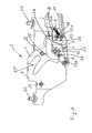
- closures 2 shown here When using the closures 2 shown here for locking from here illustrated top boxes, covering or the like, these are usually installed in pairs in a closing unit 1 shown in Figure 1, which on the vehicle on a hood, top compartment lid, top compartment frame, flap or the like can be arranged.
- the clamping unit 1 has a centrally arranged Central drive 21, which is arranged via a drive linkage 11 with the end to this Closures 2 is connected so that a in the closure 2 pivotally mounted fishing hook 4 pivoted between an open position and a closed position can be.
- the closure 2 shown in Figures 1 to 5 consists of a housing, the formed opposite sheet metal discs 3, which riveted using Distance bolts 19 are assembled into one unit.
- the fishing hook 4 is connected to a centrally disposed bearing pin 12 between the Close position ( Figure 2) and the open position ( Figure 3) pivotally mounted. At his front end, the fishing hook 4 a closing jaw 25 for engagement with a not shown here locking pin. That the closing mouth 25 opposite End has a latch 27.
- a guide pin 14 is arranged, which in the direction of projects the fishing hook 4 and projects through a slot 7 in the fishing hook 4, so that the pivoting range of the fishing hook 4 depending on the position of the Guide pin 14 and the slot 7 determined.
- rocker 5 and functional disk 6 is in the region of the rear end of the fishing hook 4 a pawl 10th pivotable about its central region on a bearing pin arranged on the housing 18 arranged.
- top, top compartment frame or the like For fastening the closure to a convertible top compartment, top, top compartment frame or the like has these flanges 23, which are for receiving screws 20 are formed.
- the closure parts 4, 5, 6, io by moving of the drive linkage 11 between the closed position shown in Figure 2 and the in Figure 3 shown opening position moves.
- the drive linkage 11 is thereby from Central drive 21 seen from the direction of the shutter 2, whereby the Rocker 5 is pivoted about the pin 17.
- the rocker 5 and the functional disk 6 Due to the articulated connection the rocker 5 and the functional disk 6 is the pivoting of the rocker fifth also the functional disk 6 is pivoted, namely about the bearing pin 12, wherein also the fixedly connected to the functional disk 6 guide pin 14 to the Bearing pin 12 is pivoted.
- the fishing hook 4 is doing by depressing the top or the top compartment lid also depressed. Due to the connection of the fishing hook 4 to the Function disc 6 limited over the guided in the slot 7 guide pin 14 the movement of the closure parts 4, 5, 6 in the manual operation alone on the fishing hook 4, which can be pivoted as far as the guide pin 14 at the closing mouth 25 opposite end of the slot 7 to the plant comes.
- a arranged on the closures 2 limit switch 24 is used for detecting and indicating the reaching of the opening and closing position of the catch hook 4.
Landscapes
- Engineering & Computer Science (AREA)
- Mechanical Engineering (AREA)
- Lock And Its Accessories (AREA)
Abstract
Description
- einem zwischen einer Öffnungslage und einer Schließlage bewegbaren, schwenkbar gelagerten Fanghaken und
- einem kraftspendenden Antriebselement, zum Antrieb des Fanghakens.
Um das Verschwenken der Sperrklinke in Richtung auf die Rückseite des Fanghakens besonders reibungslos auszugestalten, steht nach einer besonders vorteilhaften Ausgestaltung der Erfindung die Schwinge und/oder die Funktionsscheibe in der Öffnungslage mit einem von dem Fanghaken vorstehenden Federelement, insbesondere einer Blattfeder in Eingriff.
- Fig. 1
- eine perspektivische Ansicht einer Schließeinheit mit zwei Verschlüssen und einem Zentralantrieb;
- Fig. 2
- eine Vorderansicht eines Verschlusses von Figur 1 in einem durch ein Antriebselement eingestellten geschlossenen Zustand;
- Fig. 3
- eine Vorderansicht des Verschlusses von Figur 2 in einem durch das Antriebselement eingestellten geöffneten Zustand;
- Fig. 4
- eine Vorderansicht des Verschlusses von Figur 2 in einem von Hand hervorgerufenen geschlossenen Zustand mit dem sich im geöffneten Zustand befindlichen Antriebselement und
- Fig. 5
- eine Vorderansicht des Verschlusses von Figur 2 in dem von Hand geschlossenen Zustand mit dem sich zwischen dem geöffneten und dem geschlossenen Zustand befindlichen Antriebselement.
Claims (16)
- Kraftunterstützter Verschluß für Verdecke, Klappen oder dergleichen an Fahrzeugen mitdadurch gekennzeichnet, daßeinem zwischen einer Öffnungslage und einer Schließlage bewegbaren, schwenkbar gelagerten Fanghaken undeinem kraftspendenden Antriebselement zum Antrieb des Fanghakens,neben dem Fanghaken (4) eine mit dem Antriebselement (11) zusammenwirkende Funktionsscheibe (6) gelenkig gelagert ist und in spielbehafteter Mitnehmerverbindung mit dem Fanghaken (4) steht, wobei der Fanghaken (4) in einem durch das Spiel begrenzten Bereich manuell verschwenkbar ist undneben dem Fanghaken (4) eine mindestens einen Rastvorsprung aufweisende Sperrklinke (10) derart angeordnet ist, daß diese beim manuellen Verschwenken des Fanghakens (4) aus der Öffnungslage in Richtung der Schließlage mit einer entsprechend dem Rastvorsprung (28) ausgebildeten Rastmarke (27) am Fanghaken (4) in Eingriff kommt.
- Kraftunterstützter Verschluß nach Anspruch 1, dadurch gekennzeichnet, daß die Funktionsscheibe (6) gelenkig mit dem Antriebselement (11) verbunden ist.
- Kraftunterstützter Verschluß nach Anspruch 1 oder 2, dadurch gekennzeichnet, daß eine schwenkbar an einer am Verschluß (2) ortsfesten Drehachse (17) gelenkig gelagerte Schwinge (5) einerseits der Drehachse (17) gelenkig mit dem Antriebselement (11) und andererseits der Drehachse (17) gelenkig mit der Funktionsscheibe (6) verbunden ist.
- Kraftunterstützter Verschluß nach einem oder mehreren der vorhergehenden Ansprüche, dadurch gekennzeichnet, daß die spielbehaftete Mitnehmerverbindung durch eine an dem Fanghaken (4) angeordneten Führung (7) sowie einem an der Funktionsscheibe (6) angeordneten und in der Führung (7) verschiebbaren Führungselement (14) gebildet ist, wobei der Fanghaken (4) in einem durch die Führung (7) begrenzten Bereich manuell verschwenkbar ist.
- Kraftunterstützter Verschluß nach einem oder mehreren der vorhergehenden Ansprüche, dadurch gekennzeichnet, daß das Führungselement durch ein von der Funktionsscheibe (6) in Richtung auf den Fanghaken (4) vorstehenden Führungsbolzen (14) und die Führung durch ein entsprechend dem Führungsbolzen (14) ausgebildetes Langloch (7) am Fanghaken (4) gebildet ist.
- Kraftunterstützter Verschluß nach einem oder mehreren der vorhergehenden Ansprüche, dadurch gekennzeichnet, daß die Funktionsscheibe (6) einerseits ihrer gelenkigen Lagerung mit dem Antriebselement (11) verbunden ist und andererseits ihrer gelenkigen Lagerung das Führungselement (14) aufweist.
- Kraftunterstützter Verschluß nach einem oder mehreren der vorhergehenden Ansprüche, dadurch gekennzeichnet, daß die Sperrklinke (10) im Bereich eines einem Schließmaul (25) des Fanghakens (4) gegenüberliegenden hinteren Bereich angeordnet und mit dem Rastvorsprung (28) mit der im hinteren Bereich des Fanghakens (4) ausgebildeten Rastmarke (27) in Eingriff bringbar ist.
- Kraftunterstützter Verschluß nach einem oder mehreren der vorhergehenden Ansprüche, dadurch gekennzeichnet, daß die Sperrklinke (10) in eine von dem Fanghaken (4) wegweisende Richtung vorgespannt ist.
- Kraftunterstützter Verschluß nach einem oder mehreren der vorhergehenden Ansprüche, dadurch gekennzeichnet, daß die Sperrklinke (10) unter Verwendung einer einerseits an einem an der Sperrklinke (10) befestigten Bolzen (16a) und andererseits am Verschluß angeordneten Bolzen (16b) gelagerten Spiralfeder (18) vorgespannt ist.
- Kraftunterstützter Verschluß nach einem oder mehreren der vorhergehenden Ansprüche, dadurch gekennzeichnet, daß die Sperrklinke (10) in einem dem Rastvorsprung (28) gegenüberliegenden Bereich einen Vorsprung aufweist.
- Kraftunterstützter Verschluß nach einem oder mehreren der vorhergehenden Ansprüche, dadurch gekennzeichnet, daß die Sperrklinke (10) derart angeordnet ist, daß sie in der Öffnungslage mit der Schwinge (5) und/oder der Funktionsscheibe (6) in Eingriff steht und in Richtung auf den Fanghaken (4) verschwenkt ist, insbesondere an diesem anliegt.
- Kraftunterstützter Verschluß nach einem oder mehreren der vorhergehenden Ansprüche, dadurch gekennzeichnet, daß die Schwinge (5) und/oder die Funktionsscheibe (6) in der Öffnungslage mit einem von dem Fanghaken (4) vorstehenden Federelement, insbesondere einer Blattfeder (8) in Eingriff steht.
- Kraftunterstützter Verschluß nach einem oder mehreren der vorhergehenden Ansprüche, dadurch gekennzeichnet, daß der Fanghaken (4) in Richtung auf die Öffnungslage vorgespannt ist.
- Kraftunterstützter Verschluß nach einem oder mehreren der vorhergehenden Ansprüche, dadurch gekennzeichnet, daß ein einerseits an einem an dem Fanghaken (4) angeordneter Bolzen (22) und andererseits an dem Führungsbolzen (14) abgestütztes Federelement, insbesondere eine Drehfeder (15) den Fanghaken (4) in Richtung auf die Öffnungslage vorspannt.
- Kraftunterstützter Verschluß nach einem oder mehreren der vorhergehenden Ansprüche, dadurch gekennzeichnet, daß als Antriebselement eine Schubstange (11) vorgesehen ist.
- Kraftunterstützer Verschluß nach einem oder mehreren der vorhergehenden Ansprüche, dadurchgekennzeichnet, daß ein Endschalter zur Anzeige der Öffnungs- und/oder Schließlage vorgesehen ist.
Applications Claiming Priority (2)
| Application Number | Priority Date | Filing Date | Title |
|---|---|---|---|
| DE2003152489 DE10352489B3 (de) | 2003-11-07 | 2003-11-07 | Kraftunterstützter Verschluß für Verdecke, Klappen oder dergleichen an Fahrzeugen |
| DE10352489 | 2003-11-07 |
Publications (2)
| Publication Number | Publication Date |
|---|---|
| EP1529906A2 true EP1529906A2 (de) | 2005-05-11 |
| EP1529906A3 EP1529906A3 (de) | 2007-01-24 |
Family
ID=34428656
Family Applications (1)
| Application Number | Title | Priority Date | Filing Date |
|---|---|---|---|
| EP04026025A Withdrawn EP1529906A3 (de) | 2003-11-07 | 2004-11-03 | Kraftunterstützter Verschluss für Verdecke, Klappen oder dergleichen an Fahrzeugen |
Country Status (2)
| Country | Link |
|---|---|
| EP (1) | EP1529906A3 (de) |
| DE (1) | DE10352489B3 (de) |
Cited By (1)
| Publication number | Priority date | Publication date | Assignee | Title |
|---|---|---|---|---|
| FR2928108A1 (fr) * | 2008-03-03 | 2009-09-04 | Webasto Systemes Carrosserie S | Dispositif de verrouillage pour toit mobile de vehicule automobile |
Family Cites Families (4)
| Publication number | Priority date | Publication date | Assignee | Title |
|---|---|---|---|---|
| FR2605039B1 (fr) * | 1986-10-10 | 1990-07-13 | Lunke & Sohn Gmbh | Serrure pour vehicules, assistee par une source d'energie. |
| DE4111646C2 (de) * | 1991-04-10 | 1994-12-08 | Bayerische Motoren Werke Ag | Verriegelungseinrichtung, insbesondere für ein Cabrio-Faltverdeck |
| DE19927236C1 (de) * | 1999-06-15 | 2000-10-12 | Webasto Vehicle Sys Int Gmbh | Verschlußvorrichtung |
| US6886869B2 (en) * | 2001-12-14 | 2005-05-03 | Richard A. Martinez | Electromechanical locking mechanism |
-
2003
- 2003-11-07 DE DE2003152489 patent/DE10352489B3/de not_active Expired - Fee Related
-
2004
- 2004-11-03 EP EP04026025A patent/EP1529906A3/de not_active Withdrawn
Cited By (1)
| Publication number | Priority date | Publication date | Assignee | Title |
|---|---|---|---|---|
| FR2928108A1 (fr) * | 2008-03-03 | 2009-09-04 | Webasto Systemes Carrosserie S | Dispositif de verrouillage pour toit mobile de vehicule automobile |
Also Published As
| Publication number | Publication date |
|---|---|
| DE10352489B3 (de) | 2005-07-07 |
| EP1529906A3 (de) | 2007-01-24 |
Similar Documents
| Publication | Publication Date | Title |
|---|---|---|
| DE19650402C2 (de) | Verdeckkastendeckel für ein Kraftfahrzeug | |
| DE102007048969B4 (de) | Absenkbarer Dosenhalter eines Kraftfahrzeuges | |
| DE19521082C1 (de) | Kraftfahrzeug-Türgriff | |
| DE19721229B4 (de) | Verschluß für ein Verdeck eines Fahrzeuges, insbesondere eines Personenkraftwagens | |
| DE60124890T2 (de) | Einrichtung zum öffnen und schliessen einer heckklappe | |
| DE102004022426B4 (de) | Heckklappenanordnung | |
| DE102018113335A1 (de) | Integrierter tür-präsentationsmechanismus für eine verriegelung | |
| DE3636828A1 (de) | Elektrische tuerverriegelung | |
| DE102004023614B4 (de) | Vorrichtung zur Abdeckung eines Stauraums eines Kraftfahrzeugs | |
| DE19602185C1 (de) | Verschluß für ein Verdeck eines Fahrzeuges, insbesondere eines Personenkraftwagens | |
| DE19964066A1 (de) | Verschlusseinrichtung für ein Verdeck eines Fahrzeugs | |
| EP1920962B1 (de) | Verdeck für ein Kraftfahrzeug, insbesondere Cabriolet-Fahrzeug, mit einem faltbaren Dach | |
| DE19917808B4 (de) | Schließgerät für eine Fahrzeugtür | |
| EP2013047B1 (de) | Kraftfahrzeugverdeck | |
| DE3332322C2 (de) | ||
| DE19912893C2 (de) | Cabrio-Fahrzeug mit einem Verdeck | |
| DE4101288C2 (de) | ||
| EP1807276B1 (de) | Verriegelungseinrichtung für ein cabrioletverdeck | |
| EP2280840B1 (de) | Verdeck für ein kraftfahrzeug, insbesondere cabriolet-fahrzeug, mit einem faltbaren dach | |
| EP1437249B1 (de) | Verdeckverschluss eines Fahrzeugs | |
| EP2025853B1 (de) | Mitnehmervorrichtung für eine Torantriebsvorrichtung, eine solche Torantriebsvorrichtung und ein Tor | |
| DE19539085A1 (de) | Verriegelung für ein schwenkbares Dachteil eines Fahrzeuges | |
| DE10352489B3 (de) | Kraftunterstützter Verschluß für Verdecke, Klappen oder dergleichen an Fahrzeugen | |
| EP1656275B1 (de) | Cabriolet-fahrzeug | |
| EP0451583B1 (de) | Fahrzeugdach, insbesondere für Schwerkraftfahrzeuge, Busse o.dgl. |
Legal Events
| Date | Code | Title | Description |
|---|---|---|---|
| PUAI | Public reference made under article 153(3) epc to a published international application that has entered the european phase |
Free format text: ORIGINAL CODE: 0009012 |
|
| AK | Designated contracting states |
Kind code of ref document: A2 Designated state(s): AT BE BG CH CY CZ DE DK EE ES FI FR GB GR HU IE IS IT LI LU MC NL PL PT RO SE SI SK TR |
|
| AX | Request for extension of the european patent |
Extension state: AL HR LT LV MK YU |
|
| PUAL | Search report despatched |
Free format text: ORIGINAL CODE: 0009013 |
|
| AK | Designated contracting states |
Kind code of ref document: A3 Designated state(s): AT BE BG CH CY CZ DE DK EE ES FI FR GB GR HU IE IS IT LI LU MC NL PL PT RO SE SI SK TR |
|
| AX | Request for extension of the european patent |
Extension state: AL HR LT LV MK YU |
|
| AKX | Designation fees paid | ||
| STAA | Information on the status of an ep patent application or granted ep patent |
Free format text: STATUS: THE APPLICATION IS DEEMED TO BE WITHDRAWN |
|
| 18D | Application deemed to be withdrawn |
Effective date: 20070725 |
|
| REG | Reference to a national code |
Ref country code: DE Ref legal event code: 8566 |