EP1529622B1 - Formwerkzeug zum Tiefziehen von Behältern aus thermoplastischem Kunststoff - Google Patents
Formwerkzeug zum Tiefziehen von Behältern aus thermoplastischem Kunststoff Download PDFInfo
- Publication number
- EP1529622B1 EP1529622B1 EP04025850A EP04025850A EP1529622B1 EP 1529622 B1 EP1529622 B1 EP 1529622B1 EP 04025850 A EP04025850 A EP 04025850A EP 04025850 A EP04025850 A EP 04025850A EP 1529622 B1 EP1529622 B1 EP 1529622B1
- Authority
- EP
- European Patent Office
- Prior art keywords
- annular
- sleeve
- intermediate plate
- channels
- moulding tool
- Prior art date
- Legal status (The legal status is an assumption and is not a legal conclusion. Google has not performed a legal analysis and makes no representation as to the accuracy of the status listed.)
- Expired - Lifetime
Links
Images


Classifications
-
- B—PERFORMING OPERATIONS; TRANSPORTING
- B29—WORKING OF PLASTICS; WORKING OF SUBSTANCES IN A PLASTIC STATE IN GENERAL
- B29C—SHAPING OR JOINING OF PLASTICS; SHAPING OF MATERIAL IN A PLASTIC STATE, NOT OTHERWISE PROVIDED FOR; AFTER-TREATMENT OF THE SHAPED PRODUCTS, e.g. REPAIRING
- B29C51/00—Shaping by thermoforming, i.e. shaping sheets or sheet like preforms after heating, e.g. shaping sheets in matched moulds or by deep-drawing; Apparatus therefor
- B29C51/26—Component parts, details or accessories; Auxiliary operations
- B29C51/42—Heating or cooling
- B29C51/428—Heating or cooling of moulds or mould parts
-
- B—PERFORMING OPERATIONS; TRANSPORTING
- B29—WORKING OF PLASTICS; WORKING OF SUBSTANCES IN A PLASTIC STATE IN GENERAL
- B29C—SHAPING OR JOINING OF PLASTICS; SHAPING OF MATERIAL IN A PLASTIC STATE, NOT OTHERWISE PROVIDED FOR; AFTER-TREATMENT OF THE SHAPED PRODUCTS, e.g. REPAIRING
- B29C35/00—Heating, cooling or curing, e.g. crosslinking or vulcanising; Apparatus therefor
- B29C35/16—Cooling
- B29C2035/1616—Cooling using liquids
-
- B—PERFORMING OPERATIONS; TRANSPORTING
- B29—WORKING OF PLASTICS; WORKING OF SUBSTANCES IN A PLASTIC STATE IN GENERAL
- B29C—SHAPING OR JOINING OF PLASTICS; SHAPING OF MATERIAL IN A PLASTIC STATE, NOT OTHERWISE PROVIDED FOR; AFTER-TREATMENT OF THE SHAPED PRODUCTS, e.g. REPAIRING
- B29C51/00—Shaping by thermoforming, i.e. shaping sheets or sheet like preforms after heating, e.g. shaping sheets in matched moulds or by deep-drawing; Apparatus therefor
- B29C51/04—Combined thermoforming and prestretching, e.g. biaxial stretching
-
- B—PERFORMING OPERATIONS; TRANSPORTING
- B29—WORKING OF PLASTICS; WORKING OF SUBSTANCES IN A PLASTIC STATE IN GENERAL
- B29K—INDEXING SCHEME ASSOCIATED WITH SUBCLASSES B29B, B29C OR B29D, RELATING TO MOULDING MATERIALS OR TO MATERIALS FOR MOULDS, REINFORCEMENTS, FILLERS OR PREFORMED PARTS, e.g. INSERTS
- B29K2827/00—Use of polyvinylhalogenides or derivatives thereof as mould material
- B29K2827/12—Use of polyvinylhalogenides or derivatives thereof as mould material containing fluorine
- B29K2827/18—PTFE, i.e. polytetrafluoroethylene, e.g. ePTFE, i.e. expanded polytetrafluoroethylene
Definitions
- the invention is based on a mold according to the preamble of claim 1. With this are thermoformed containers from a heated sheet of thermoplastic material by means of compressed air and optionally punched out.
- a disadvantage of this cooling water supply is the indirect cooling of the stretch limb, since the cooling insert is in contact with the outer circumference of the hold-down, and not integrated in the hold-down.
- each hold-down is directly cooled to the lower, the film web facing area.
- the hold-down device is formed from an outer pot and an inner pot, which are designed so that they have a gap for passing a cooling liquid.
- the supply and removal of the cooling liquid takes place from the closed end face of the hold-down device via two tubes, which are displaceably guided in the tool top plate and are in communication with bores in the tool top plate.
- connecting lines for supplying and discharging the cooling liquid to the intermediate space are provided in the end face.
- a disadvantage of this cooling water supply is the space required by the pipes, which does not allow the use of smaller diameter containers structurally.
- a limit is in the diameter range of 70mm, that is smaller diameter, this cooling water guide can not be applied.
- a further disadvantage is that when pressure is applied to the downholder on the front side, as is advantageous in various processes, the surface of the pipes is not pressurized, consequently the force on the downholder is lower.
- a general problem with this indirect cooling is the good sealing of the coolant to prevent leakage safely.
- the invention has for its object to overcome the disadvantages of the prior art, while maintaining the advantage of direct cooling of the blank holder in the film web facing area.
- a restriction of the application to certain diameter ranges should not be given.
- An influence on the hold-down force when pressurizing the end face of the hold-down device with compressed air should not occur.
- the installation of safe-acting seals to prevent leakage should be possible in a simple, safe way.
- the embodiment according to the invention should also be applicable when the stretching aid is sealingly guided in the hold-down device or an additional blocking piston is arranged sealingly and displaceably in the hold-down device.
- the mold consists of the upper part 1 and the lower part 2.
- the latter comprises a base plate 3, a cooling block 4 and in this per mold cavity inserted mold inserts 5 single row as shown or multi-row with the shape of the container to be produced.
- the mold inserts 5 are integrally formed or two-piece and bear in combined forming and punching molds on the upper, the film web 7 side facing a cutting edge 8.
- the upper part 1 is composed of a top plate 11, an intermediate plate 10, the die 12 and arranged in each mold nest hold-down 13.
- Each hold-down 13 is resiliently held and pushes after punching the container and after opening the mold this from the die bore.
- a stretching aid 14 is arranged in Niederhalter 13 . All stretchers 14 are each connected via a rod 15 with a common support plate 16. This can be moved over a drive device shown as arrow 17. It optionally has a bore 18 communicating with a compressed air source via a main valve and communicating with the axial bore 19 in the rod 15 for supplying the shaping air. However, the shaping air supply / removal can also take place via bores 39, 40 into the interior of the downholder 13.
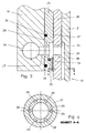
- each hold-down device 13 consists of a cup-shaped inner element 20 and a cup-shaped outer element 21, which are connected to one another and welded at the lower end or sealed to one another via a seal 41. Between both a ring channel 22 is incorporated on the film web 7 facing end face. In the intermediate plate 10 sits a sleeve 23 which has two annular channels 24, 25.
- the one annular channel 24 is in this case via holes 27, 42 with a bore 26 in the intermediate plate 10 for supplying a cooling liquid and a bore 38 in the outer member 20 and a channel 28 or via a plurality of channels 28 (see Figure 4) in the inner member 20 with the annular channel 22 in connection.
- the derivation of Coolant takes place via an opposite channel 29 or via a plurality of channels 29 in the inner element 20, which lead from the annular groove 22 to a bore 30 in the outer element 21 and thus to the annular channel 25. From there, bores 31, 32 lead to the bore 33 in the intermediate plate 10, which serves to derive the cooling liquid.
- sealing lips 34 are part of the sleeve 23 and are pressed for better sealing effect with an annular spring 35. Sealing rings 36 are used to seal static stressed areas.
- the remaining between the annular chambers 24, 25 region is formed according to an embodiment of the invention as a guide portion 37 with appropriate fit and surface finish, to bring about a good guide for the outer member 21 of the blank holder 13.
- the sleeve 37 is preferably made of plastic.
- PTFE is very suitable as a material.
Landscapes
- Engineering & Computer Science (AREA)
- Mechanical Engineering (AREA)
- Blow-Moulding Or Thermoforming Of Plastics Or The Like (AREA)
- Moulds For Moulding Plastics Or The Like (AREA)
Description
- Die Erfindung geht aus von einem Formwerkzeug nach dem Oberbegriff des Anspruches 1. Mit diesem werden aus einer erwärmten Folienbahn aus thermoplastischem Kunststoff mittels Druckluft Behälter tiefgezogen und ggf. ausgestanzt.
- Aus der
DE 29605248 ist ein derartiges Formwerkzeug bekannt, bei dem in der Matrize eine Hülse sitzt, die zwei Ringkammern zum Zuführen and Abführen eines Kühlmediums aufweist. - Nachteilig bei dieser Kühlwasserzufuhr ist die indirekte Abkühlung des Streckhelfus, da der Kühleinsatz in Kontakt mit dem Außenumfang des Niederhalters ist, und nicht in dem Niederhalter integriert.
- Aus der
DE 43 26 190 A1 ist ein derartiges Formwerkzeug bekannt, bei dem jeder Niederhalter direkt gekühlt ist bis in den unteren, der Folienbahn zugewandten Bereich. Um dies zu erreichen wird der Niederhalter aus einem Außentopf und einem Innentopf gebildet, die so gestaltet sind, dass sie einen Zwischenraum zum Durchleiten einer Kühlflüssigkeit aufweisen. Die Zufuhr und Abfuhr der Kühlflüssigkeit erfolgt von der geschlossenen Stirnseite des Niederhalters her über zwei Rohre, die verschiebbar in der Werkzeugoberplatte geführt sind und mit Bohrungen in der Werkzeugoberplatte in Verbindung stehen. In der Stirnseite sind des weiteren Verbindungsleitungen zum Zuführen und Abführen der Kühlflüssigkeit zum Zwischenraum vorgesehen. - Nachteilig bei dieser Kühlwasserzufuhr ist der Platzbedarf der Rohre, der den Einsatz für im Durchmesser kleinere Behälter baulich nicht erlaubt. Eine Grenze liegt im Durchmesserbereich von 70mm, das heißt bei kleineren Durchmessern kann diese Kühlwasserführung nicht angewendet werden. Ein weiterer Nachteil liegt darin, dass bei einer Druckbeaufschlagung des Niederhalters auf der Stirnseite, wie sie bei verschiedenen Verfahrensabläufen vorteilhaft ist, die Fläche der Rohre nicht mit Druck beaufschlagt wird, folglich die Kraft auf den Niederhalter geringer ausfällt. Ein generelles Problem bei dieser indirekten Kühlung liegt in der guten Abdichtung der Kühlflüssigkeit, um eine Leckage sicher zu verhindern.
- Aus der
DE 31 09 415 A1 ist eine indirekte Kühlung des Niederhalters bekannt, indem dieser an einer gekühlten Kühlbuchse im unteren Bereich anliegt. Diese Art indirekte Kühlung ist von der Kühlwirkung her nicht so effektiv wie eine direkte Kühlung, insbesondere was den vorderen, der Folienbahn zugewandten Bereich anbelangt. Zum Erzielen einer hohen Taktzahl kommt es aber gerade auf ein gutes Kühlen dieses Bereiches an. - Aus der
DE 201 16 922 U1 ist ein Formwerkzeug bekannt, bei dem der Niederhalter ebenfalls zweigeteilt mit einem Zwischenraum ausgebildet ist. Hier dient dieser Zwischentraum allerdings der Formluftzufuhr. In den Zwischenraum zugeführt wird die Formluft über Bohrungen in der Kopfplatte und über Ringkanäle in Niederhalter und Kopfplatte. Die Kühlung selbst kann hier nur indirekt erfolgen. - Der Erfindung liegt die Aufgabe zugrunde, die geschilderten Nachteile des Standes der Technik zu überwinden unter Beibehaltung des Vorteiles einer direkten Kühlung des Niederhalters im der Folienbahn zugewandten Bereich. Eine Beschränkung der Anwendung auf bestimmte Durchmesserbereiche sollte nicht gegeben sein. Eine Beeinflussung der Niederhalterkraft bei Beaufschlagung der Stirnseite des Niederhalters mit Druckluft sollte nicht eintreten. Die Montage von sicher wirkenden Dichtungen zum Verhindern einer Leckage sollte auf einfache, sichere Weise möglich sein. Die erfindungsgemäße Ausführung sollte sich auch dann anwenden lassen, wenn der Streckhelfer dichtend im Niederhalter geführt ist oder ein zusätzlicher Sperrkolben dichtend und verschiebbar im Niederhalter angeordnet ist.
- Gelöst ist diese Aufgabe erfindungsgemäß durch die im Kennzeichen des Hauptanspruchs angegebenen Maßnahmen.
- Weitere bevorzugte Ausgestaltungen der Erfindung ergeben sich aus den übrigen, in den Unteransprüchen genannten Merkmalen.
- Das Formwerkzeug ist anhand der schematischen Zeichnungen näher beschrieben. Es zeigen:
- Figur 1
- einen Querschnitt durch das Formwerkzeug in geschlossener Stellung vor Einleitung des Tiefziehvorganges.
- Figur 2
- eine vergrößerte Darstellung des Niederhalters im Oberteil des Formwerkzeuges.
- Figur 3
- eine weiter vergrößerte Darstellung des Niederhalters.
- Figur 4
- einen Schnitt entlang der Linie A - A in Figur 3.
- Das Formwerkzeug besteht aus dem Oberteil 1 und dem Unterteil 2. Letzteres umfasst eine Grundplatte 3, einen Kühlblock 4 und in diesen pro Formnest eingesetzte Formeinsätze 5 einreihig wie dargestellt oder mehrreihig mit der Gestalt der herzustellenden Behälter. Die Formeinsätze 5 sind einteilig oder zweiteilig ausgebildet und tragen bei kombiniert formenden und stanzenden Formwerkzeugen an der oberen, der Folienbahn 7 zugewandtem Seite, eine Schnittkante 8. Eine Kühlung der Formeinsätze 5 erfolgt über die Kammer 9 zwischen Kühlblock 4 und Außenform der Formeinsätze 5 in bekannter Weise. Zum Ausschieben der geformten und ausgestanzten Behälter aus den Formeinsätzen 5 dient je ein verschiebbarer Formboden 6.
- Das Oberteil 1 setzt sich zusammen aus einer Kopfplatte 11, einer Zwischenplatte 10, der Matrize 12 und einem in jedem Formnest angeordneten Niederhalter 13. Jeder Niederhalter 13 ist federnd nachgiebig gehalten und schiebt nach dem Ausstanzen der Behälter und nach dem Öffnen des Formwerkzeuges diese aus der Matrizenbohrung. Im Niederhalter 13 ist ein Streckhelfer 14 angeordnet. Alle Streckhelfer 14 sind jeweils über eine Stange 15 mit einer gemeinsamen Halteplatte 16 verbunden. Diese kann über eine als Pfeil 17 dargestellte Antriebseinrichtung verschoben werden. Sie weist wahlweise eine mit einer Druckluftquelle über ein Hauptventil in Verbindung stehende Bohrung 18 auf, die mit der Axialbohrung 19 in der Stange 15 zum Zuführen der Formluft in Verbindung steht. Die Formluftzufuhr/-abfuhr kann aber auch über Bohrungen 39, 40 ins Innere der Niederhalter 13 erfolgen.
- Die Erfindung betrifft die Gestaltung der Niederhalter 13, ihre Kühlung einschließlich Abdichtung und ihre Führung. Wie insbesondere aus den Figuren 2 und 3 ersichtlich besteht jeder Niederhalter 13 aus einem topfförmigen Innenelement 20 und einem topfförmigen Außenelement 21, die miteinander verbunden und am unteren Ende verschweißt oder über eine Dichtung 41 zueinander abgedichtet sind. Zwischen beiden ist auf der der Folienbahn 7 zugewandten Stirnseite ein Ringkanal 22 eingearbeitet. In der Zwischenplatte 10 sitzt eine Hülse 23, die zwei Ringkanäle 24, 25 aufweist. Der eine Ringkanal 24 steht dabei über Bohrungen 27, 42 mit einer Bohrung 26 in der Zwischenplatte 10 zum Zuführen einer Kühlflüssigkeit sowie über eine Bohrung 38 im Außenelement 20 und über einen Kanal 28 oder über mehrere Kanäle 28 (siehe Figur 4) im Innenelement 20 mit dem Ringkanal 22 in Verbindung. Die Ableitung der Kühlflüssigkeit erfolgt über einen gegenüberliegenden Kanal 29 oder über mehrere Kanäle 29 im Innenelement 20, die von der Ringnut 22 bis zu einer Bohrung 30 im Außenelement 21 und damit zum Ringkanal 25 führen. Von dort aus führen Bohrungen 31, 32 bis zur Bohrung 33 in der Zwischenplatte 10, die zum Ableiten der Kühlflüssigkeit dient.
- Zur Abdichtung der Kühlflüssigkeit dienen Dichtlippen 34 (siehe Fig. 3), die Teil der Hülse 23 sind und zur besseren Dichtwirkung mit einer Ringfeder 35 angedrückt werden. Dichtringe 36 dienen der Abdichtung statische beanspruchter Bereiche.
Der zwischen den Ringkammern 24, 25 verbleibende Bereich ist gemäß einer Weiterbildung der Erfindung als Führungsbereich 37 ausgebildet mit entsprechender Passung und Oberflächengüte, um eine gute Führung für das Außenelement 21 des Niederhalters 13 herbeizuführen. - Die Hülse 37 ist vorzugsweise aus Kunststoff ausgeführt. Insbesondere PTFE ist als Werkstoff sehr geeignet.
Claims (5)
- Formwerkzeug zum Tiefziehen von Behältern aus einer erwärmten Folienbahn (7) aus thermoplastischem Kunststoff, bestehend aus Oberteil (1) und Unterteil (2), wobei das Unterteil (2) die Formeinsätze (5) trägt und das Oberteil (1) eine Zwischenplatte (10), eine Matrize (12), pro Formnest einen Niederhalter (13), bestehend aus einem Außenelement (21) und einem Innenelement (20) mit einem Zwischenraum zum Durchleiten einer Kühlflüssigkeit und einen in jedem Niederhalter (13) angeordneten, über eine Stange (15) verschiebbaren Streckhelfer (14) aufweist, dadurch gekennzeichnet, dass in der Zwischenplatte (10) eine Hülse (23) sitzt, die zwei Ringkammern (24, 25) zum Zuführen und Abführen eines Kühlmediums mit je einer Dichtlippe (34) aufweist, wobei von den Ringkammern (24, 25) aus Bohrungen (30, 38) zu den in dem Innenelement (20) angeordneten Kanälen (28, 29) führen, die in einer Ringkammer (22) zwischen Außenelement (21) und Innenelement (20) münden.
- Formwerkzeug nach Anspruch 1, dadurch gekennzeichnet, dass mehrere Kanäle (28) zum Zuleiten und/oder mehrere Kanäle (29) zum Ableiten der Kühlflüssigkeit im Innenelement (20) angeordnet sind.
- Formwerkzeug nach Anspruch 1 oder 2, dadurch gekennzeichnet, dass an der Hülse (23) zwischen den beiden Ringkammern (24, 25) ein Führungsbereich (37) für den Niederhalter (13) ausgebildet ist.
- Formwerkzeug nach einem der Ansprüche 1 bis 3, dadurch gekennzeichnet, dass die Dichtlippen (34) von einer Ringfeder (35) vorgespannt werden.
- Formwerkzeug nach einem der Ansprüche 1 bis 4, dadurch gekennzeichnet, dass die Hülse (37) aus einem Kunststoff, vorzugsweise aus PTFE besteht.
Applications Claiming Priority (2)
| Application Number | Priority Date | Filing Date | Title |
|---|---|---|---|
| DE10351585A DE10351585B4 (de) | 2003-11-05 | 2003-11-05 | Formwerkzeug zum Tiefziehen von Behältern aus thermoplastischen Kunststoff |
| DE10351585 | 2003-11-05 |
Publications (3)
| Publication Number | Publication Date |
|---|---|
| EP1529622A2 EP1529622A2 (de) | 2005-05-11 |
| EP1529622A3 EP1529622A3 (de) | 2006-11-15 |
| EP1529622B1 true EP1529622B1 (de) | 2007-08-01 |
Family
ID=34428561
Family Applications (1)
| Application Number | Title | Priority Date | Filing Date |
|---|---|---|---|
| EP04025850A Expired - Lifetime EP1529622B1 (de) | 2003-11-05 | 2004-10-30 | Formwerkzeug zum Tiefziehen von Behältern aus thermoplastischem Kunststoff |
Country Status (4)
| Country | Link |
|---|---|
| EP (1) | EP1529622B1 (de) |
| AT (1) | ATE368561T1 (de) |
| DE (2) | DE10351585B4 (de) |
| DK (1) | DK1529622T3 (de) |
Families Citing this family (3)
| Publication number | Priority date | Publication date | Assignee | Title |
|---|---|---|---|---|
| NL1030680C2 (nl) * | 2005-12-15 | 2007-06-18 | Anbeco B V | Inrichting voor het thermovormen van producten. |
| NL1034235C2 (nl) * | 2007-08-07 | 2009-02-10 | Bosch Sprang Beheer B V | Thermovorminrichting met verbeterde drukflenskoeling. |
| DE102020107321B3 (de) * | 2020-03-17 | 2021-03-25 | Illig Maschinenbau Gmbh & Co. Kg | Formwerkzeug oder Form-/Stanzwerkzeug zum Tiefziehen von Behältern aus einer erwärmten Folienbahn aus thermoplastischem Kunststoff |
Family Cites Families (10)
| Publication number | Priority date | Publication date | Assignee | Title |
|---|---|---|---|---|
| DE3109415C1 (de) * | 1981-03-12 | 1982-11-04 | Adolf Illig Maschinenbau Gmbh & Co, 7100 Heilbronn | Formwerkzeug zur Herstellung von Bechern aus erwaermter thermoplastischer Kunststoffolie |
| DE4326190A1 (de) * | 1993-08-04 | 1995-02-09 | Marbach Werkzeugbau Gmbh | Thermoformwerkzeug |
| DE4418064C1 (de) * | 1994-05-24 | 1995-09-07 | Illig Maschinenbau Adolf | Verfahren zum Temperieren der beiden Werkzeughälften eines Formwerkzeugs zum Tiefziehen einer Kunststoffolie und Vorrichtung zur Durchführung des Verfahrens |
| DE29605248U1 (de) * | 1996-03-21 | 1997-07-17 | Gizeh-Werk GmbH, 51702 Bergneustadt | Formwerkzeug |
| DE29605249U1 (de) * | 1996-03-21 | 1997-07-17 | Gizeh Werk Gmbh | Formwerkzeug |
| DE19838289A1 (de) * | 1998-08-24 | 2000-03-09 | Illig Maschinenbau Adolf | Formwerkzeug zur Herstellung von Bechern aus erwärmter thermoplastischer Kunststoffolie |
| DE19838290A1 (de) * | 1998-08-24 | 2000-03-09 | Illig Maschinenbau Adolf | Formwerkzeug zur Herstellung von Bechern aus erwärmter thermoplastischer Kunststoffolie |
| DE10017042B4 (de) * | 2000-04-05 | 2004-09-30 | Adolf Illig Maschinenbau Gmbh & Co.Kg | Form-/Stanzwerkzeug zum Herstellen von Behältern aus einer thermoplastischen Kunststofffolie |
| DE10119567C1 (de) * | 2001-04-21 | 2002-06-20 | Illig Maschinenbau Adolf | Verfahren zum Kühlen der beiden Werkzeughälften eines Formwerkzeuges und Mischeinheit zur Durchführung des Verfahrens |
| DE20116922U1 (de) * | 2001-10-15 | 2002-01-24 | Marbach Werkzeugbau GmbH, 74080 Heilbronn | Thermoformwerkzeug |
-
2003
- 2003-11-05 DE DE10351585A patent/DE10351585B4/de not_active Expired - Fee Related
-
2004
- 2004-10-30 AT AT04025850T patent/ATE368561T1/de active
- 2004-10-30 EP EP04025850A patent/EP1529622B1/de not_active Expired - Lifetime
- 2004-10-30 DE DE502004004496T patent/DE502004004496D1/de not_active Expired - Lifetime
- 2004-10-30 DK DK04025850T patent/DK1529622T3/da active
Also Published As
| Publication number | Publication date |
|---|---|
| EP1529622A3 (de) | 2006-11-15 |
| ATE368561T1 (de) | 2007-08-15 |
| EP1529622A2 (de) | 2005-05-11 |
| DK1529622T3 (da) | 2007-11-19 |
| DE10351585A1 (de) | 2005-06-16 |
| DE10351585B4 (de) | 2005-12-29 |
| DE502004004496D1 (de) | 2007-09-13 |
Similar Documents
| Publication | Publication Date | Title |
|---|---|---|
| DE3107865C2 (de) | Formwerkzeug zum Herstellen gratfreier Formlinge aus Kunststoff | |
| DE10043209A1 (de) | Flexibles Werkzeug zur Umformung eines Werkstücks | |
| EP1842651A2 (de) | Formwerkzeug zum Tiefziehen und Ausstanzen von Behältern aus einer erwärmten thermoplastischen Kunststofffolie und Verfahren zum Tiefziehen und Ausstanzen von Behältern | |
| EP1486313B1 (de) | Formwerkzeug zum Tiefziehen von Behältern aus thermoplastischen Kunststoff | |
| DE102008013264B3 (de) | Verfahren zum Tiefziehen von Behältern aus einer Folienbahn aus thermoplastischem Kunststoff | |
| DE102014000814B4 (de) | Ventileinheit | |
| DE20116922U1 (de) | Thermoformwerkzeug | |
| DE10351585B4 (de) | Formwerkzeug zum Tiefziehen von Behältern aus thermoplastischen Kunststoff | |
| DE102007037748B3 (de) | Formwerkzeug und Verfahren zum Tiefziehen von Behältern aus einer erwärmten Folienbahn aus thermoplastischem Kunststoff | |
| EP1361036B1 (de) | Formwerkzeug zum Tiefziehen von Behältern aus thermoplastischem Kunststoff, wobei in den Stempel ein Ventil integriert ist | |
| DE2937605A1 (de) | Vorrichtung zum umgiessen oder umspritzen der raender von flaechigen bauteilen | |
| EP2595751A1 (de) | Mikrofluidische vorrichtung und verfahren zu deren herstellung | |
| DE3541767A1 (de) | Kunststoff-formteil mit angeformten oder eingeformten gummielastischen teilen | |
| DE3149962A1 (de) | Vorrichtung zum thermoformen von formlingen | |
| EP4434721A1 (de) | Formwerkzeug zur herstellung von formteilen und verfahren zur herstellung von formteilen unter verwendung eines formwerkzeugs | |
| DE9109287U1 (de) | Formwerkzeug zur Herstellung von Kunststoffbechern | |
| DE10220700B4 (de) | Formwerkzeug zum Tiefziehen von Behältern aus thermoplastischem Kuststoff | |
| CH467144A (de) | Verfahren und Vorrichtung zum Herstellen flaschenartiger Behälter aus Kunststoff | |
| DE10220701A1 (de) | Formwerkzeug zum Tiefziehen von Behältern aus thermoplastischem Kunststoff | |
| EP1514668B1 (de) | Formwerkzeug zum Tiefziehen von Behältern aus thermoplastischem Kunststoff | |
| DE102018007824B3 (de) | Verfahren zum Aufbringen eines Etiketts auf ein tiefgezogenes Formteil und Formwerkzeug zum Durchführen des Verfahrens | |
| DE4421979C1 (de) | Form- Stanz-Werkzeug zum Herstellen von Behältern aus thermoplastischer Kunststoffolie | |
| DE2716680B1 (de) | Vorrichtung zum Formen,Stanzen und Stapeln von Teilen aus thermoplastischer Kunststoffolie | |
| DE9421923U1 (de) | Form-Stanzwerkzeug zum Herstellen von Behältern aus thermoplastischer Kunststoffolie | |
| DE102024102391A1 (de) | Blasvorrichtung zum Expandieren eines vorgeformten Hohlkörpers, Streckblasmaschine und Verfahren zum Expandieren eines Hohlkörpers |
Legal Events
| Date | Code | Title | Description |
|---|---|---|---|
| PUAI | Public reference made under article 153(3) epc to a published international application that has entered the european phase |
Free format text: ORIGINAL CODE: 0009012 |
|
| AK | Designated contracting states |
Kind code of ref document: A2 Designated state(s): AT BE BG CH CY CZ DE DK EE ES FI FR GB GR HU IE IT LI LU MC NL PL PT RO SE SI SK TR |
|
| AX | Request for extension of the european patent |
Extension state: AL HR LT LV MK |
|
| RAP1 | Party data changed (applicant data changed or rights of an application transferred) |
Owner name: ILLIG MASCHINENBAU GMBH & CO. KG |
|
| PUAL | Search report despatched |
Free format text: ORIGINAL CODE: 0009013 |
|
| AK | Designated contracting states |
Kind code of ref document: A3 Designated state(s): AT BE BG CH CY CZ DE DK EE ES FI FR GB GR HU IE IT LI LU MC NL PL PT RO SE SI SK TR |
|
| AX | Request for extension of the european patent |
Extension state: AL HR LT LV MK |
|
| RIC1 | Information provided on ipc code assigned before grant |
Ipc: B29C 51/04 20060101ALI20061010BHEP Ipc: B29C 51/30 20060101ALI20061010BHEP Ipc: B29C 51/42 20060101AFI20061010BHEP |
|
| 17P | Request for examination filed |
Effective date: 20061201 |
|
| GRAP | Despatch of communication of intention to grant a patent |
Free format text: ORIGINAL CODE: EPIDOSNIGR1 |
|
| GRAS | Grant fee paid |
Free format text: ORIGINAL CODE: EPIDOSNIGR3 |
|
| GRAA | (expected) grant |
Free format text: ORIGINAL CODE: 0009210 |
|
| AKX | Designation fees paid |
Designated state(s): AT BE BG CH CY CZ DE DK EE ES FI FR GB GR HU IE IT LI LU MC NL PL PT RO SE SI SK TR |
|
| AK | Designated contracting states |
Kind code of ref document: B1 Designated state(s): AT BE BG CH CY CZ DE DK EE ES FI FR GB GR HU IE IT LI LU MC NL PL PT RO SE SI SK TR |
|
| REG | Reference to a national code |
Ref country code: GB Ref legal event code: FG4D Free format text: NOT ENGLISH |
|
| REG | Reference to a national code |
Ref country code: CH Ref legal event code: EP |
|
| REG | Reference to a national code |
Ref country code: IE Ref legal event code: FG4D Free format text: LANGUAGE OF EP DOCUMENT: GERMAN |
|
| REF | Corresponds to: |
Ref document number: 502004004496 Country of ref document: DE Date of ref document: 20070913 Kind code of ref document: P |
|
| GBT | Gb: translation of ep patent filed (gb section 77(6)(a)/1977) |
Effective date: 20071024 |
|
| REG | Reference to a national code |
Ref country code: DK Ref legal event code: T3 |
|
| PG25 | Lapsed in a contracting state [announced via postgrant information from national office to epo] |
Ref country code: ES Free format text: LAPSE BECAUSE OF FAILURE TO SUBMIT A TRANSLATION OF THE DESCRIPTION OR TO PAY THE FEE WITHIN THE PRESCRIBED TIME-LIMIT Effective date: 20071112 Ref country code: BG Free format text: LAPSE BECAUSE OF FAILURE TO SUBMIT A TRANSLATION OF THE DESCRIPTION OR TO PAY THE FEE WITHIN THE PRESCRIBED TIME-LIMIT Effective date: 20071101 Ref country code: FI Free format text: LAPSE BECAUSE OF FAILURE TO SUBMIT A TRANSLATION OF THE DESCRIPTION OR TO PAY THE FEE WITHIN THE PRESCRIBED TIME-LIMIT Effective date: 20070801 |
|
| PG25 | Lapsed in a contracting state [announced via postgrant information from national office to epo] |
Ref country code: PL Free format text: LAPSE BECAUSE OF FAILURE TO SUBMIT A TRANSLATION OF THE DESCRIPTION OR TO PAY THE FEE WITHIN THE PRESCRIBED TIME-LIMIT Effective date: 20070801 |
|
| REG | Reference to a national code |
Ref country code: IE Ref legal event code: FD4D |
|
| EN | Fr: translation not filed | ||
| BERE | Be: lapsed |
Owner name: ILLIG MASCHINENBAU G.M.B.H. & CO. KG Effective date: 20071031 |
|
| PG25 | Lapsed in a contracting state [announced via postgrant information from national office to epo] |
Ref country code: GR Free format text: LAPSE BECAUSE OF FAILURE TO SUBMIT A TRANSLATION OF THE DESCRIPTION OR TO PAY THE FEE WITHIN THE PRESCRIBED TIME-LIMIT Effective date: 20071102 |
|
| PG25 | Lapsed in a contracting state [announced via postgrant information from national office to epo] |
Ref country code: SK Free format text: LAPSE BECAUSE OF FAILURE TO SUBMIT A TRANSLATION OF THE DESCRIPTION OR TO PAY THE FEE WITHIN THE PRESCRIBED TIME-LIMIT Effective date: 20070801 Ref country code: CZ Free format text: LAPSE BECAUSE OF FAILURE TO SUBMIT A TRANSLATION OF THE DESCRIPTION OR TO PAY THE FEE WITHIN THE PRESCRIBED TIME-LIMIT Effective date: 20070801 Ref country code: MC Free format text: LAPSE BECAUSE OF NON-PAYMENT OF DUE FEES Effective date: 20071031 Ref country code: IE Free format text: LAPSE BECAUSE OF FAILURE TO SUBMIT A TRANSLATION OF THE DESCRIPTION OR TO PAY THE FEE WITHIN THE PRESCRIBED TIME-LIMIT Effective date: 20070801 Ref country code: PT Free format text: LAPSE BECAUSE OF FAILURE TO SUBMIT A TRANSLATION OF THE DESCRIPTION OR TO PAY THE FEE WITHIN THE PRESCRIBED TIME-LIMIT Effective date: 20080102 |
|
| PLBE | No opposition filed within time limit |
Free format text: ORIGINAL CODE: 0009261 |
|
| STAA | Information on the status of an ep patent application or granted ep patent |
Free format text: STATUS: NO OPPOSITION FILED WITHIN TIME LIMIT |
|
| PG25 | Lapsed in a contracting state [announced via postgrant information from national office to epo] |
Ref country code: SE Free format text: LAPSE BECAUSE OF FAILURE TO SUBMIT A TRANSLATION OF THE DESCRIPTION OR TO PAY THE FEE WITHIN THE PRESCRIBED TIME-LIMIT Effective date: 20071101 Ref country code: RO Free format text: LAPSE BECAUSE OF FAILURE TO SUBMIT A TRANSLATION OF THE DESCRIPTION OR TO PAY THE FEE WITHIN THE PRESCRIBED TIME-LIMIT Effective date: 20070801 |
|
| 26N | No opposition filed |
Effective date: 20080506 |
|
| PG25 | Lapsed in a contracting state [announced via postgrant information from national office to epo] |
Ref country code: FR Free format text: LAPSE BECAUSE OF FAILURE TO SUBMIT A TRANSLATION OF THE DESCRIPTION OR TO PAY THE FEE WITHIN THE PRESCRIBED TIME-LIMIT Effective date: 20080328 |
|
| PG25 | Lapsed in a contracting state [announced via postgrant information from national office to epo] |
Ref country code: BE Free format text: LAPSE BECAUSE OF NON-PAYMENT OF DUE FEES Effective date: 20071031 |
|
| PG25 | Lapsed in a contracting state [announced via postgrant information from national office to epo] |
Ref country code: EE Free format text: LAPSE BECAUSE OF FAILURE TO SUBMIT A TRANSLATION OF THE DESCRIPTION OR TO PAY THE FEE WITHIN THE PRESCRIBED TIME-LIMIT Effective date: 20070801 |
|
| REG | Reference to a national code |
Ref country code: CH Ref legal event code: PL |
|
| PG25 | Lapsed in a contracting state [announced via postgrant information from national office to epo] |
Ref country code: SI Free format text: LAPSE BECAUSE OF FAILURE TO SUBMIT A TRANSLATION OF THE DESCRIPTION OR TO PAY THE FEE WITHIN THE PRESCRIBED TIME-LIMIT Effective date: 20070801 |
|
| PG25 | Lapsed in a contracting state [announced via postgrant information from national office to epo] |
Ref country code: CY Free format text: LAPSE BECAUSE OF FAILURE TO SUBMIT A TRANSLATION OF THE DESCRIPTION OR TO PAY THE FEE WITHIN THE PRESCRIBED TIME-LIMIT Effective date: 20070801 |
|
| PG25 | Lapsed in a contracting state [announced via postgrant information from national office to epo] |
Ref country code: LU Free format text: LAPSE BECAUSE OF NON-PAYMENT OF DUE FEES Effective date: 20071030 |
|
| PG25 | Lapsed in a contracting state [announced via postgrant information from national office to epo] |
Ref country code: HU Free format text: LAPSE BECAUSE OF FAILURE TO SUBMIT A TRANSLATION OF THE DESCRIPTION OR TO PAY THE FEE WITHIN THE PRESCRIBED TIME-LIMIT Effective date: 20080202 Ref country code: TR Free format text: LAPSE BECAUSE OF FAILURE TO SUBMIT A TRANSLATION OF THE DESCRIPTION OR TO PAY THE FEE WITHIN THE PRESCRIBED TIME-LIMIT Effective date: 20070801 |
|
| PG25 | Lapsed in a contracting state [announced via postgrant information from national office to epo] |
Ref country code: LI Free format text: LAPSE BECAUSE OF NON-PAYMENT OF DUE FEES Effective date: 20081031 Ref country code: CH Free format text: LAPSE BECAUSE OF NON-PAYMENT OF DUE FEES Effective date: 20081031 |
|
| PGFP | Annual fee paid to national office [announced via postgrant information from national office to epo] |
Ref country code: NL Payment date: 20221021 Year of fee payment: 19 |
|
| PGFP | Annual fee paid to national office [announced via postgrant information from national office to epo] |
Ref country code: IT Payment date: 20221031 Year of fee payment: 19 Ref country code: GB Payment date: 20221024 Year of fee payment: 19 Ref country code: DK Payment date: 20221021 Year of fee payment: 19 Ref country code: DE Payment date: 20221020 Year of fee payment: 19 Ref country code: AT Payment date: 20221018 Year of fee payment: 19 |
|
| REG | Reference to a national code |
Ref country code: DE Ref legal event code: R119 Ref document number: 502004004496 Country of ref document: DE |
|
| REG | Reference to a national code |
Ref country code: DK Ref legal event code: EBP Effective date: 20231031 |
|
| REG | Reference to a national code |
Ref country code: NL Ref legal event code: MM Effective date: 20231101 |
|
| REG | Reference to a national code |
Ref country code: AT Ref legal event code: MM01 Ref document number: 368561 Country of ref document: AT Kind code of ref document: T Effective date: 20231030 |
|
| GBPC | Gb: european patent ceased through non-payment of renewal fee |
Effective date: 20231030 |
|
| PG25 | Lapsed in a contracting state [announced via postgrant information from national office to epo] |
Ref country code: GB Free format text: LAPSE BECAUSE OF NON-PAYMENT OF DUE FEES Effective date: 20231030 |
|
| PG25 | Lapsed in a contracting state [announced via postgrant information from national office to epo] |
Ref country code: NL Free format text: LAPSE BECAUSE OF NON-PAYMENT OF DUE FEES Effective date: 20231101 |
|
| PG25 | Lapsed in a contracting state [announced via postgrant information from national office to epo] |
Ref country code: AT Free format text: LAPSE BECAUSE OF NON-PAYMENT OF DUE FEES Effective date: 20231030 |
|
| PG25 | Lapsed in a contracting state [announced via postgrant information from national office to epo] |
Ref country code: NL Free format text: LAPSE BECAUSE OF NON-PAYMENT OF DUE FEES Effective date: 20231101 Ref country code: GB Free format text: LAPSE BECAUSE OF NON-PAYMENT OF DUE FEES Effective date: 20231030 Ref country code: DE Free format text: LAPSE BECAUSE OF NON-PAYMENT OF DUE FEES Effective date: 20240501 Ref country code: AT Free format text: LAPSE BECAUSE OF NON-PAYMENT OF DUE FEES Effective date: 20231030 |
|
| PG25 | Lapsed in a contracting state [announced via postgrant information from national office to epo] |
Ref country code: DK Free format text: LAPSE BECAUSE OF NON-PAYMENT OF DUE FEES Effective date: 20231031 |
|
| PG25 | Lapsed in a contracting state [announced via postgrant information from national office to epo] |
Ref country code: DK Free format text: LAPSE BECAUSE OF NON-PAYMENT OF DUE FEES Effective date: 20231031 |
|
| PG25 | Lapsed in a contracting state [announced via postgrant information from national office to epo] |
Ref country code: IT Free format text: LAPSE BECAUSE OF NON-PAYMENT OF DUE FEES Effective date: 20231030 |
|
| PG25 | Lapsed in a contracting state [announced via postgrant information from national office to epo] |
Ref country code: IT Free format text: LAPSE BECAUSE OF NON-PAYMENT OF DUE FEES Effective date: 20231030 |