EP1529499A2 - Dispositif support destiné à être implanté dans l'os pour traitement orthodontique - Google Patents
Dispositif support destiné à être implanté dans l'os pour traitement orthodontique Download PDFInfo
- Publication number
- EP1529499A2 EP1529499A2 EP04105480A EP04105480A EP1529499A2 EP 1529499 A2 EP1529499 A2 EP 1529499A2 EP 04105480 A EP04105480 A EP 04105480A EP 04105480 A EP04105480 A EP 04105480A EP 1529499 A2 EP1529499 A2 EP 1529499A2
- Authority
- EP
- European Patent Office
- Prior art keywords
- support device
- osteogenic
- groove
- orthodontic
- osteogenic support
- Prior art date
- Legal status (The legal status is an assumption and is not a legal conclusion. Google has not performed a legal analysis and makes no representation as to the accuracy of the status listed.)
- Withdrawn
Links
- 230000002188 osteogenic effect Effects 0.000 title claims abstract description 33
- 238000011282 treatment Methods 0.000 title claims abstract description 26
- 238000006073 displacement reaction Methods 0.000 description 10
- 238000010276 construction Methods 0.000 description 3
- 230000015572 biosynthetic process Effects 0.000 description 2
- 230000000452 restraining effect Effects 0.000 description 2
- 230000000153 supplemental effect Effects 0.000 description 2
- 239000004744 fabric Substances 0.000 description 1
- 230000007794 irritation Effects 0.000 description 1
- 239000000463 material Substances 0.000 description 1
- 230000002093 peripheral effect Effects 0.000 description 1
- 239000004033 plastic Substances 0.000 description 1
Images


Classifications
-
- A—HUMAN NECESSITIES
- A61—MEDICAL OR VETERINARY SCIENCE; HYGIENE
- A61C—DENTISTRY; APPARATUS OR METHODS FOR ORAL OR DENTAL HYGIENE
- A61C7/00—Orthodontics, i.e. obtaining or maintaining the desired position of teeth, e.g. by straightening, evening, regulating, separating, or by correcting malocclusions
- A61C7/12—Brackets; Arch wires; Combinations thereof; Accessories therefor
- A61C7/14—Brackets; Fixing brackets to teeth
-
- A—HUMAN NECESSITIES
- A61—MEDICAL OR VETERINARY SCIENCE; HYGIENE
- A61C—DENTISTRY; APPARATUS OR METHODS FOR ORAL OR DENTAL HYGIENE
- A61C7/00—Orthodontics, i.e. obtaining or maintaining the desired position of teeth, e.g. by straightening, evening, regulating, separating, or by correcting malocclusions
- A61C7/12—Brackets; Arch wires; Combinations thereof; Accessories therefor
-
- A—HUMAN NECESSITIES
- A61—MEDICAL OR VETERINARY SCIENCE; HYGIENE
- A61C—DENTISTRY; APPARATUS OR METHODS FOR ORAL OR DENTAL HYGIENE
- A61C8/00—Means to be fixed to the jaw-bone for consolidating natural teeth or for fixing dental prostheses thereon; Dental implants; Implanting tools
-
- A—HUMAN NECESSITIES
- A61—MEDICAL OR VETERINARY SCIENCE; HYGIENE
- A61C—DENTISTRY; APPARATUS OR METHODS FOR ORAL OR DENTAL HYGIENE
- A61C8/00—Means to be fixed to the jaw-bone for consolidating natural teeth or for fixing dental prostheses thereon; Dental implants; Implanting tools
- A61C8/0018—Means to be fixed to the jaw-bone for consolidating natural teeth or for fixing dental prostheses thereon; Dental implants; Implanting tools characterised by the shape
- A61C8/0022—Self-screwing
-
- A—HUMAN NECESSITIES
- A61—MEDICAL OR VETERINARY SCIENCE; HYGIENE
- A61C—DENTISTRY; APPARATUS OR METHODS FOR ORAL OR DENTAL HYGIENE
- A61C8/00—Means to be fixed to the jaw-bone for consolidating natural teeth or for fixing dental prostheses thereon; Dental implants; Implanting tools
- A61C8/0093—Features of implants not otherwise provided for
- A61C8/0096—Implants for use in orthodontic treatment
Definitions
- the present invention relates to an orthodontic treatment device. More particularly, the present invention relates to an improved osteogenic support device for an orthodontic treatment enabling aerial or three-dimensional displacement of target teeth being treated for orthodontic purposes.
- a jaw bone is used to apply an extra force to teeth of an orthodontic patient. That is, a screw is pierced in the jaw bone for a limited time period so that the head of the pierced screw is wire-connected to brackets attached on teeth to provide an additional force to the target teeth of an orthodontic patient.
- a tiny piece of hygienic nailing device such as a hygienic screw is planted in a jaw bone structure of the orthodontic patient to provide an extra strain to the teeth.
- an extra wire is hooked up both on an exposed side portion of the hygienic piece planted in the patient's jaw bone and on the base wire that retains each bracket on the teeth.
- a conventional hygienic screw is disclosed in Korean Utility Model No. 20-0233786 and Korean Utility Model No. 20-0249419 where the screw with a head part and a threaded part is provide to prevent the orthodontic wire from slipping down onto the gum of an orthodontic patient and from subsequent gum irritation.
- a disadvantage of the prior art is that it is relatively difficult to apply an angular wire such as rectangular wire for orthodontic treatment.
- Another disadvantage is that the screw application limits a displacement of force to horizontal and vertical movements, that is, to two dimensional tooth movements.
- the present invention is contrived to overcome the conventional disadvantages. Accordingly, it is an object of the present invention to provide an osteogenic support device for an orthodontic treatment enabling aerial or three-dimensional displacement of target teeth being treated for orthodontic purposes. Another object is to controllably triple the orthodontic treatment force by enabling a simultaneous application of a wire, an elastic band and an additional aid such as a hook, thereby improving efficiency of orthodontic treatment.
- the osteogenic support device for an orthodontic treatment comprises a platform defined by a top side, a bottom side and an outer periphery.
- a lower projection having an end extends from the bottom side of the platform so as to become pierced in an osteogenic jaw bone structure of an orthodontic patient.
- An extension head having a top surface and a bottom surface, and the top surface is substantially recessed to form a top groove across the head.
- the top groove is defined by side walls and a bed surface, with the bed surface substantially perpendicular to each of the side walls.
- the bottom surface of the extension head is recessed to form a first bottom groove.
- the bottom surface of the extension head is further recessed to form a second bottom groove so that the bottom grooves are partitioned by the connector.
- the bottom grooves are substantially parallel to each other and to the top groove. It is also preferred that the bottom grooves are each surfaced in a dome format.
- a substantially rectangular wire is selectively provided to fit in the top groove.
- the extension head is holed from the side walls through an outer periphery of the extension head to form through-holes.
- the through-holes are each substantially perpendicular to the top groove.
- the lower projection is substantially threaded.
- the connector is cylindrical in shape.
- the osteogenic support device for an orthodontic treatment are numerous in that: (1)the bottom grooves parallel to the top groove enables aerial or three-dimensional displacement of target teeth being treated for orthodontic purposes by providing stable and sufficient seats for a rectangular wire and a rubber band, thereby improving efficiency of orthodontic treatment; (2) the osteogenic support device combines into the aerial or three-dimensional force the top groove for receiving the rectangular wire, bottom grooves for being hooked by the rubber band and the holes for allowing application of an additional restraining aid such as a hook, thereby generating manageably enhanced orthodontic force for optimal orthodontic treatment; and (3) the top groove, bottom grooves and holes in the support device are formed in a supplemental format such that an orthodontic specialist can easily elect and apply respective merits depending on orthodontic patients and treatment requirements, thereby maximizing product reliability.
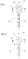
- FIGS. 1 and 2 each show an osteogenic support device 10 for an orthodontic treatment according to the present invention where a screw threading direction differentiates FIG. 1 from FIG. 2.
- FIG. 3 show a lengthwise cross-section of FIG. 1 to detail construction of the osteogenic support device 10 .
- FIGS. 4 and 5 show each an orthodontic application of the support device 10 .
- the osteogenic support device 10 for an orthodontic treatment comprises a platform 12 defined by a top side 14, a bottom side 16 and an outer periphery 18 .
- a lower projection 20 having an end 22 is provided to extend from the bottom side 16 of the platform 12 so as to become pierced in an osteogenic jaw bone structure of an orthodontic patient.
- the osteogenic support device 10 further comprises an extension head 24 having a top surface 26 and a bottom surface 28 where the top surface 26 is substantially recessed to form a top groove 30 across the head 24 where the top groove 30 is defined by side walls 32 and a bed surface 34 .
- the bed surface 34 is substantially perpendicular to each of the side walls 32.
- the bottom surface 28 of the extension head 24 is slightly recessed to form a first bottom groove 36 .
- the support device 10 also comprises a connector 40 linking a central portion 42 of the top side 14 of the platform 12 to a central portion 44 of the bottom surface 28 of the head 24 in adjacency to the first bottom groove 36 .
- the bottom surface 28 of the extension head 24 may be further recessed to form a second bottom groove 38 so that the bottom grooves 36, 38 become partitioned by the connector 40.
- bottom grooves 36, 38 are substantially parallel to each other.
- the bottom grooves 36, 38 are substantially parallel to the top groove 30.
- the bottom grooves 36, 38 are each surfaced in a dome format across the bottom surface 28.
- the osteogenic support device 10 further comprises a substantially rectangular wire 46 to fit in the top groove 30 whereas the extension head 24 is holed from the side walls 32 through an outer periphery 48 of the extension head 24 to form through-holes 50 .
- the through-holes 50 are each substantially perpendicular to the top groove 30 .
- An additional aid such as a tension spring and elastic hook may be employed to become hooked in the through-holes 50 for additional force being applied to the target teeth 52.
- the lower projection 20 is substantially threaded to either right or left direction to form right or left threads 58
- the connector 40 is cylindrical in shape to allow a source for an additional force that can be further applied to the target teeth 52 .
- brackets 54 are detachably glued on each outer surface of teeth 52 and an orthodontic wire 46 is aligned along the brackets 54 to become attached to the brackets 54 so as to generate strain for teeth realignment.
- the osteogenic support device 10 is selectively utilized in conjunction with the orthodontic wire 46 in a rectangular formation.
- the orthodontic wire 46 may have elasticity within allowance of the orthodontic treatment requirements.
- the device 10 with a screw formation is partially planted in upper or lower jaw bone through a selected area of a gum 53 of the patient during the orthodontic treatment.
- an elastic member 56 selected from a rubber ring, a plastic string, a fabric string and other string type connection materials. So the combination of the rectangular wire 46 and the rubber ring 56 enables facilitates an aerial or three-dimensional control of the target teeth 52.
- a three-dimensional displacement by the application of the support device 10 is implemented in three-way combination a first displacement along a teeth alignment ( x ), a second displacement along a vertical alignment ( y ) perpendicular to the teeth alignment, and a third displacement along a cross-teeth alignment ( z ) perpendicular to the teeth and vertical alignments, thereby realizing aerial or three-dimensional teeth displacement.
- the lower projection 20 is substantially threaded to facilitate its planting in the osteogenic jaw bone structure through the gum 53 . Also, it is preferred that the lower projection 20 ranges between about 5.0 mm and 8.0 mm in length.
- the platform 12 is formed in a multi-sided alignment.
- the outer periphery 18 of the platform 12 may be formed in a six-sided peripheral alignment to facilitate the partial planting of the osteogenic support device 10 in a target portion of the orthodontic patient's jaw bone structure.
- the outer periphery 18 of the platform 12 may be substantially surface-piled to facilitate manipulation of the support device 10 to plant the lower projection 20 in the jaw bone structure and remove the planting after completion of the orthodontic treatment.
- an advantage of the osteogenic support device 10 is that the bottom grooves 36, 38 parallel to the top groove 30 enables aerial or three-dimensional displacement of target teeth being treated for orthodontic purposes by providing stable and sufficient seats for the rectangular wire 46 and the rubber band 56 , thereby improving efficiency of orthodontic treatment.
- the osteogenic support device 10 combines into the aerial or three-dimensional force the top groove 30 for receiving the rectangular wire 46 , bottom grooves 36, 38 for being hooked by the rubber band 56 and the holes 50 for allowing application of an additional restraining aid such as a hook, thereby generating manageably enhanced orthodontic force for optimal orthodontic treatment.
- the top groove 30 , bottom grooves 36, 38 and holes 50 in the support device 10 are formed in a supplemental format such that an orthodontic specialist can easily elect and apply respective merits depending on orthodontic patients and treatment requirements, thereby maximizing product reliability.
Landscapes
- Health & Medical Sciences (AREA)
- Oral & Maxillofacial Surgery (AREA)
- Dentistry (AREA)
- Epidemiology (AREA)
- Life Sciences & Earth Sciences (AREA)
- Animal Behavior & Ethology (AREA)
- General Health & Medical Sciences (AREA)
- Public Health (AREA)
- Veterinary Medicine (AREA)
- Orthopedic Medicine & Surgery (AREA)
- Dental Tools And Instruments Or Auxiliary Dental Instruments (AREA)
Applications Claiming Priority (2)
| Application Number | Priority Date | Filing Date | Title |
|---|---|---|---|
| KR1020030078813A KR20050044214A (ko) | 2003-11-07 | 2003-11-07 | 브라켓 헤드 타입의 치열 교정용 스크류 |
| KR2003078813T | 2003-11-07 |
Publications (2)
| Publication Number | Publication Date |
|---|---|
| EP1529499A2 true EP1529499A2 (fr) | 2005-05-11 |
| EP1529499A3 EP1529499A3 (fr) | 2005-12-14 |
Family
ID=34545798
Family Applications (1)
| Application Number | Title | Priority Date | Filing Date |
|---|---|---|---|
| EP04105480A Withdrawn EP1529499A3 (fr) | 2003-11-07 | 2004-11-03 | Dispositif support destiné à être implanté dans l'os pour traitement orthodontique |
Country Status (4)
| Country | Link |
|---|---|
| US (1) | US20050100854A1 (fr) |
| EP (1) | EP1529499A3 (fr) |
| KR (1) | KR20050044214A (fr) |
| TW (1) | TWI285545B (fr) |
Cited By (1)
| Publication number | Priority date | Publication date | Assignee | Title |
|---|---|---|---|---|
| WO2008045909A1 (fr) * | 2006-10-10 | 2008-04-17 | Ormco Corporation | Plaquette de fixation à une dent présentant des parties de retenue du fil, et procédés associés |
Families Citing this family (12)
| Publication number | Priority date | Publication date | Assignee | Title |
|---|---|---|---|---|
| US20060199138A1 (en) * | 2003-11-25 | 2006-09-07 | Leonardo Corti | Orthodontic microscrew |
| KR100727095B1 (ko) | 2005-05-17 | 2007-06-13 | 조선대학교산학협력단 | 임플랜트와 이를 이용한 치열 교정용 고정장치 |
| JP2007111317A (ja) * | 2005-10-21 | 2007-05-10 | Kazuhiro Ueki | 矯正歯科治療用埋込具 |
| KR100671540B1 (ko) * | 2006-02-28 | 2007-01-25 | 김종완 | 치열교정용 스크류 |
| JP2007244676A (ja) * | 2006-03-16 | 2007-09-27 | Univ Nihon | アバットメント |
| EP2010094B1 (fr) * | 2006-04-25 | 2015-07-22 | D B Orthodontics Ltd | Appareil d'implant orthodontique |
| ITPR20060040A1 (it) * | 2006-04-28 | 2007-10-29 | Antonio Costa | Dispositivo ortodontico a vite e filo e procedimento di assemblaggio del suddetto dispositivo ortodontico tramite un dispositivo ortodontico a filo ed un dispositivo ortodontico a vite. |
| US7806686B2 (en) * | 2006-08-24 | 2010-10-05 | Toads Llc | Anchor apparatus and method for orthodontic appliances |
| CA2713050A1 (fr) * | 2008-02-01 | 2009-08-06 | Synthes Usa, Llc | Plaque d'ancrage d'os orthodontique avec tampon a mailles |
| TWM360687U (en) * | 2008-07-10 | 2009-07-11 | nai-chang Yu | Orthodontic temporary anchorage device |
| IT1400805B1 (it) * | 2010-07-02 | 2013-07-02 | Vigolo | Vite di ancoraggio ortodontico e procedimento per la sua realizzazione |
| BR202018003759U2 (pt) * | 2018-02-26 | 2019-09-10 | Nagassawa Eduardo | disposição construtiva introduzida em mini-implante para ancoragem ortodôntica |
Family Cites Families (10)
| Publication number | Priority date | Publication date | Assignee | Title |
|---|---|---|---|---|
| DE3220240A1 (de) * | 1982-05-07 | 1983-12-01 | Winfried Dr. 8000 München Schütz | Einrichtung zur kieferorthopaedischen zahnregulierung |
| US5697779A (en) * | 1995-06-07 | 1997-12-16 | Ormco Corporation | Temporary implant for use as an anchor in the mouth |
| US6193509B1 (en) * | 1998-04-02 | 2001-02-27 | John Devincenzo | Bony anchor extender |
| KR200183865Y1 (ko) * | 1999-12-31 | 2000-06-01 | 경희문 | 치열교정용 간접접착 브라켓 포지셔너 |
| KR200207524Y1 (ko) * | 2000-07-12 | 2000-12-15 | 박영철 | 교정틀 고정구 |
| KR200230655Y1 (ko) * | 2000-12-29 | 2001-07-03 | 경희문 | 치열교정용 간접접착 브라켓 포지셔너 |
| KR200233786Y1 (ko) * | 2001-03-07 | 2001-09-26 | 박효상 | 치열 교정용 스크류 |
| DE10132088B4 (de) * | 2001-07-05 | 2005-09-29 | Altatec Medizintechnische Elemente Gmbh & Co. Kg | Kieferorthopädisches Implantatsystem zur Zahnmobilisierung |
| TW532144U (en) * | 2002-06-04 | 2003-05-11 | Jeng-Yi Lin | Screw device for jaw correction |
| US7172416B2 (en) * | 2003-12-11 | 2007-02-06 | Cheng-Yi Lin | Screw device for orthodontic treatment |
-
2003
- 2003-11-07 KR KR1020030078813A patent/KR20050044214A/ko not_active Ceased
-
2004
- 2004-11-03 EP EP04105480A patent/EP1529499A3/fr not_active Withdrawn
- 2004-11-03 US US10/904,314 patent/US20050100854A1/en not_active Abandoned
- 2004-11-08 TW TW093133952A patent/TWI285545B/zh not_active IP Right Cessation
Cited By (1)
| Publication number | Priority date | Publication date | Assignee | Title |
|---|---|---|---|---|
| WO2008045909A1 (fr) * | 2006-10-10 | 2008-04-17 | Ormco Corporation | Plaquette de fixation à une dent présentant des parties de retenue du fil, et procédés associés |
Also Published As
| Publication number | Publication date |
|---|---|
| KR20050044214A (ko) | 2005-05-12 |
| TWI285545B (en) | 2007-08-21 |
| EP1529499A3 (fr) | 2005-12-14 |
| US20050100854A1 (en) | 2005-05-12 |
| TW200520732A (en) | 2005-07-01 |
Similar Documents
| Publication | Publication Date | Title |
|---|---|---|
| US6575742B2 (en) | Osteogenic support device for orthodontic treatment | |
| KR101841345B1 (ko) | 저작성 치아 교정기 | |
| JP6751712B2 (ja) | 再位置決め顎エレメントを有する歯科器具 | |
| JP5611343B2 (ja) | 歯科インプラントアセンブリ | |
| US7234934B2 (en) | Computer configured appliance for orthodontic correction of malocclusions | |
| US20050100854A1 (en) | Osteogenic support device for orthodontic treatment | |
| US20210369417A1 (en) | Bracket attachment system | |
| JP2005185705A (ja) | 歯科矯正用支持体 | |
| AU713845B2 (en) | Customized dental abutment | |
| JP2016185325A (ja) | 熱成形されたアライナに対するカスタムエクステンションの製造法 | |
| JP2014528310A (ja) | 口腔内装具とその製造方法及び調節方法 | |
| TW201618732A (zh) | 牙齒矯正系統 | |
| JP6854291B2 (ja) | 舌側歯科矯正装具 | |
| JPH11164843A (ja) | 歯科矯正用支持体 | |
| ES2879320T3 (es) | Aparato de ortodoncia para odontología | |
| KR101851106B1 (ko) | 설측용 치열 교정장치 | |
| KR101940741B1 (ko) | 치아교정용 바이트가이드 | |
| ITPD20100207A1 (it) | Vite di ancoraggio ortodontico e procedimento per la sua realizzazione | |
| JP5542516B2 (ja) | 歯列矯正用ブラケット | |
| ES1305971U (es) | Instrumento dental en forma de concha, conjunto de aparato dental en forma de concha, y sistema de ortodoncia dental | |
| JP5728610B1 (ja) | 歯科矯正用インプラント装置 | |
| JPH0141332B2 (fr) | ||
| US11696847B2 (en) | Apparatus and methods to convert dental, oral, orthodontic appliances, retainers, and dentures into a multifunctional oral appliance | |
| JP2002263120A (ja) | 義歯製作装置 | |
| US20060019211A1 (en) | Bracket having .017" x .024" arch slot, wire system and tube system |
Legal Events
| Date | Code | Title | Description |
|---|---|---|---|
| PUAI | Public reference made under article 153(3) epc to a published international application that has entered the european phase |
Free format text: ORIGINAL CODE: 0009012 |
|
| 17P | Request for examination filed |
Effective date: 20041111 |
|
| AK | Designated contracting states |
Kind code of ref document: A2 Designated state(s): AT BE BG CH CY CZ DE DK EE ES FI FR GB GR HU IE IS IT LI LU MC NL PL PT RO SE SI SK TR |
|
| AX | Request for extension of the european patent |
Extension state: AL HR LT LV MK YU |
|
| PUAL | Search report despatched |
Free format text: ORIGINAL CODE: 0009013 |
|
| AK | Designated contracting states |
Kind code of ref document: A3 Designated state(s): AT BE BG CH CY CZ DE DK EE ES FI FR GB GR HU IE IS IT LI LU MC NL PL PT RO SE SI SK TR |
|
| AX | Request for extension of the european patent |
Extension state: AL HR LT LV MK YU |
|
| 17Q | First examination report despatched |
Effective date: 20060713 |
|
| AKX | Designation fees paid |
Designated state(s): AT BE BG CH CY CZ DE DK EE ES FI FR GB GR HU IE IS IT LI LU MC NL PL PT RO SE SI SK TR |
|
| STAA | Information on the status of an ep patent application or granted ep patent |
Free format text: STATUS: THE APPLICATION IS DEEMED TO BE WITHDRAWN |
|
| 18D | Application deemed to be withdrawn |
Effective date: 20070124 |