EP1529472A1 - Elektrisches Haushaltsgerät zur Nahrungszubereitung mit einer lösbar an einem Gehäuse gekoppelten Zusatzvorrichtung - Google Patents
Elektrisches Haushaltsgerät zur Nahrungszubereitung mit einer lösbar an einem Gehäuse gekoppelten Zusatzvorrichtung Download PDFInfo
- Publication number
- EP1529472A1 EP1529472A1 EP04356163A EP04356163A EP1529472A1 EP 1529472 A1 EP1529472 A1 EP 1529472A1 EP 04356163 A EP04356163 A EP 04356163A EP 04356163 A EP04356163 A EP 04356163A EP 1529472 A1 EP1529472 A1 EP 1529472A1
- Authority
- EP
- European Patent Office
- Prior art keywords
- housing
- accessory
- sleeve
- assembly
- appliance according
- Prior art date
- Legal status (The legal status is an assumption and is not a legal conclusion. Google has not performed a legal analysis and makes no representation as to the accuracy of the status listed.)
- Granted
Links
Images


Classifications
-
- A—HUMAN NECESSITIES
- A47—FURNITURE; DOMESTIC ARTICLES OR APPLIANCES; COFFEE MILLS; SPICE MILLS; SUCTION CLEANERS IN GENERAL
- A47J—KITCHEN EQUIPMENT; COFFEE MILLS; SPICE MILLS; APPARATUS FOR MAKING BEVERAGES
- A47J43/00—Implements for preparing or holding food, not provided for in other groups of this subclass
- A47J43/04—Machines for domestic use not covered elsewhere, e.g. for grinding, mixing, stirring, kneading, emulsifying, whipping or beating foodstuffs, e.g. power-driven
- A47J43/06—Machines for domestic use not covered elsewhere, e.g. for grinding, mixing, stirring, kneading, emulsifying, whipping or beating foodstuffs, e.g. power-driven with a plurality of interchangeable working units, e.g. with a single driving-unit
-
- A—HUMAN NECESSITIES
- A47—FURNITURE; DOMESTIC ARTICLES OR APPLIANCES; COFFEE MILLS; SPICE MILLS; SUCTION CLEANERS IN GENERAL
- A47J—KITCHEN EQUIPMENT; COFFEE MILLS; SPICE MILLS; APPARATUS FOR MAKING BEVERAGES
- A47J43/00—Implements for preparing or holding food, not provided for in other groups of this subclass
- A47J43/04—Machines for domestic use not covered elsewhere, e.g. for grinding, mixing, stirring, kneading, emulsifying, whipping or beating foodstuffs, e.g. power-driven
- A47J43/044—Machines for domestic use not covered elsewhere, e.g. for grinding, mixing, stirring, kneading, emulsifying, whipping or beating foodstuffs, e.g. power-driven with tools driven from the top side
- A47J2043/04409—Apparatus of hand held type
- A47J2043/04418—Apparatus of hand held type with housing extending perpendicular, e.g. horizontally, from the tool axis
Definitions
- the present invention relates to the general technical field of apparatus electrical household appliances.
- the present invention relates more particularly the devices comprising an accessory coupled so removable on a housing, the housing and the accessory each having a connecting sleeve provided with a thread allowing the coupling by screwing the accessory on the housing.
- an equipped household appliance of a beater accessory which is removably mounted on a housing of mixer, the accessory and the housing each having an assembly sleeve provided with a thread allowing the coupling by screwing of one on the other.
- a such appliance is also provided with an immobilizing lock the accessory in a specific position relative to the housing, the lock having a lug movably mounted on one of the sleeves engaging on one notch on the other sleeve.
- Such a lock however has the disadvantage of immobilizing the accessory in a determined position which can not, for reasons of tolerances of manufacture, correspond to the screwing position for which the body of the accessory comes in axial support against the housing. It follows that with such device, when the accessory is immobilized by the lock, it results a game between the body of the accessory and the body of the housing that allows the entry into vibration of the body of the accessory relative to the housing during operation of the device. However, such vibrations of the body of the accessory on the housing generate noise that is unpleasant for the user and gives a negative impression on the quality of the device.
- the following invention aims to overcome these disadvantages.
- Such a characteristic has the advantage of eliminating the appearance of parasitic vibrations of the accessory relative to the housing.
- the gear element is movable by relative to the connecting sleeve supporting it, the toothed element being resiliently returned to a locking position in which the teeth of the toothed element protrude from the connecting sleeve
- Such a characteristic makes it possible to produce an effective locking device does not generate significant frictional force between the gear element and the locking ribs when screwing the accessory.
- the gear element is secured to an unlock button to erase the teeth of the element to teeth on the inside of the connecting sleeve supporting it.
- the unlocking button and the toothed element are carried by the same part, the latter integrating a elastic return element of the gear element.
- Such a characteristic makes it possible to simplify the production of the device of locking by limiting the number of pieces.
- the angular distribution of locking ribs and the angular extent of the gear element are such that at least one blocking rib is permanently facing the element to teeth when the accessory is coupled to the housing.
- the threads of the sleeves of assembly consist of quarter-turn threads which allow the coupling of the accessory on the housing according to four different positions, offset from each other by 90 °.
- Such a characteristic has the advantage of offering the choice in the position assembly of the accessory.
- the housing comprises a body comprising an elongate manual grip zone enclosing the engine and has a longitudinal end with the assembly sleeve, the latter having an opening opposite which is arranged a rotary drive driven by the engine.
- the gear element is carried by the assembly sleeve of the housing and the ribs are worn by the connecting sleeve of the accessory.
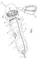
- FIG. 1 represents a household appliance comprising a housing 1 of elongated form, a longitudinal end of which is intended to be coupled to an accessory, such as a drummer accessory 100.
- the housing 1 comprises a body of circular section consisting of two shells 10 made of plastic assembled one on the other and comprises, in the central part of the housing 1, a manual gripping zone having a restricted section.
- the housing 1 encloses a motor 2 connected to a reducer 3 by a transmission shaft, shown in dotted lines on the Figure 1, the gearbox 3 being provided with a rotary drive 31 two-speed arranged opposite an opening made in the partition closing the end Housing 1 to be coupled to the accessory.
- the opposite end of the casing 1 has in turn an opening for the passage of a cord power supply 4.
- the operation of the motor 2 is controlled by a control button 5 disposed at the central portion of the housing 1, the housing body 1 having at this location an impression 11 adapted to the shape of a thumb of which the bottom is formed by the actuating surface of the control knob 5.
- the end of the housing 1 intended to be coupled to the drummer accessory 100 is equipped with an assembly sleeve 1A having a section reduced by relative to the gripping area of the housing 1 so that it results a shoulder 12 serving as an axial stop to the accessory 100 during its assembly on the housing 1.
- the assembly sleeve 1A has four nets 13 quarter of rotation regularly distributed on the periphery of the assembly sleeve 1A, these threads 13 allowing the coupling by screwing the drummer accessory 100 on the housing 1 according to four positions offset from each other by 90 °.
- the beater accessory 100 is provided with a sleeve assembly 100A made of plastic material engaging around the sleeve assembly 1A housing 1 and whose inner periphery has threads quarter turn 101 adapted to cooperate with the nets 13 of the housing 1.
- the assembly sleeve 100A has an outside diameter adapted for continuously extend the body of the housing 1 when the edge of the sleeve 100A is in abutment against the shoulder 12 of the housing 1.
- the beater accessory 100 also comprises an input shaft 102 which comes mate with the rotational drive 31 of the gearbox, this input shaft 102 being connected by means of a gear train to two oriented whips 103 parallel to each other and transversely to the shaft 102.
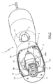
- the immobilization of the accessory drummer 100 in its final position is provided by a locking member 6 comprising a gear element 60 disposed through an opening of the joining sleeve 1A, the gear element 60 having teeth 60A longitudinal elastically projecting outside the body of the housing 1 of to cooperate with locking ribs 104 formed, every 15 ° approximately, on the inner periphery of the assembly sleeve 100A of the drummer accessory 100.
- the locking member 6 also comprises an unlocking button 61 disposed in an opening of the housing body 1, at the edge of the sleeve assembly 1A.
- the front portion of the unlocking button 61 is linked to the toothed element 60 by a connecting element 62, the button of unlocking 61 allowing when depressed, the deletion of teeth 60A to inside the body of the housing 1.
- the locking member 6 comprises also a support tongue 63 extending from the rear part of the unlocking button 61 and whose curved end bears on the body of the gearbox 3 and serves as a pivot point for the locking member 6.
- the elastic return of the gear element 60 in the locking position is provided by an elastic tongue 64 integrated with the locking member 6.
- the elastic tongue 64 extends obliquely under the connecting element 62 and has an end bearing on the body of the gearbox 3, under the gear element 60, the gearbox 3 having at this point a diameter reduced.
- the element teeth 60 extends transversely in a generally arcuate shape. circle that matches the curvature of the body of the housing 1 and preferentially on an angular aperture greater than 15 ° so that at least two locking ribs 104 is permanently engaged on the element to teeth 60 when the accessory 100 is coupled to the housing 1.
- flanks of the teeth 60A of the gear element 60 and locking ribs 104 contacting each other in the direction unscrewing extend substantially radially to the screw axis of to prevent the unscrewing of the accessory 100.
- the flanks teeth 60A of the toothed element 60 and locking ribs 104 coming into contact with each other while screwing the accessory are inclined in order to generate a radial force leading to the automatic erasure of the element 60 with teeth inside the body of the housing during the screwing of the accessory 100.
- the distribution of the teeth 60A on the gear element 60 is as it allows the engagement of a locking rib 104 between two 60A teeth every 5 °.
- Figures 6 and 7 respectively illustrate, by way of examples, the use of the housing with the control knob facing up and to the side.
- the teeth 60A of the element 60 are engaged on the ribs 104 of the sleeve assembly 100A, and the gear element 60 is automatically cleared in the body of the housing 1, by compression of the elastic tongue 64, under stress generated by the inclination of the flanks of the teeth 60A and the ribs 104 which are mutually in contact in the direction of screwing.
- the edge of assembly sleeve 100A of the accessory comes into abutment against the shoulder 12 of the housing 1
- the screwing torque applied by the user generates an axial compressive force of the drummer accessory 100 on the body housing 1 which causes an imperceptible elastic deformation of the joining sleeves 1A, 100A.
- the tight distribution of 60A teeth the toothed element 60 then makes it possible to block the accessory 100 in the final tightening position to within 5 degrees, ie in a position where the assembly sleeve 100A of accessory 100 is applied under stress against the housing 1.
- Such a locking device thus has the advantage of allowing the immobilization of the accessory on the housing in a position where the body of the accessory is in axial support against the body of the housing, which allows to significantly reduce the risk of vibration of the accessory on the housing.
- Such a device also has the advantage of being independent of manufacturing tolerances or wear of the threads.
- the angular distribution of the teeth on the gear element will be preferentially adapted to the value of the thread pitch of the quarter-turn threads used.
- this distribution will be such that the angular fineness of the blockage less than the angle of rotation of the accessory allowed by the deformation elastic material when the body of the accessory comes to bear against the housing and that a usual tightening torque is applied to the accessory.
- the number of ribs on the body of the accessory and the extent angle of the toothed element may be modified so as to vary the number of blocking ribs permanently engaged in the gear element when the accessory is coupled to the housing to ensure a predetermined minimum locking torque.
- the apparatus according to the invention may be used with another type accessory, such as a mixing desk.
- the lock may be worn by the assembly sleeve belonging to the accessory and the locking ribs will then be worn by the sleeve assembly belonging to the housing of the device.
Landscapes
- Engineering & Computer Science (AREA)
- Mechanical Engineering (AREA)
- Food Science & Technology (AREA)
- Food-Manufacturing Devices (AREA)
- Cookers (AREA)
- Gear Transmission (AREA)
Applications Claiming Priority (2)
| Application Number | Priority Date | Filing Date | Title |
|---|---|---|---|
| FR0312915 | 2003-11-04 | ||
| FR0312915A FR2861566B1 (fr) | 2003-11-04 | 2003-11-04 | Appareil electromenager de preparation culinaire comportant un accessoire accouple de maniere amovible sur un boitier |
Publications (2)
| Publication Number | Publication Date |
|---|---|
| EP1529472A1 true EP1529472A1 (de) | 2005-05-11 |
| EP1529472B1 EP1529472B1 (de) | 2007-01-24 |
Family
ID=34429872
Family Applications (1)
| Application Number | Title | Priority Date | Filing Date |
|---|---|---|---|
| EP04356163A Expired - Lifetime EP1529472B1 (de) | 2003-11-04 | 2004-10-08 | Elektrisches Haushaltsgerät zur Nahrungszubereitung mit einer lösbar an einem Gehäuse gekoppelten Zusatzvorrichtung |
Country Status (5)
| Country | Link |
|---|---|
| EP (1) | EP1529472B1 (de) |
| AT (1) | ATE352244T1 (de) |
| DE (1) | DE602004004473D1 (de) |
| ES (1) | ES2278291T3 (de) |
| FR (1) | FR2861566B1 (de) |
Cited By (4)
| Publication number | Priority date | Publication date | Assignee | Title |
|---|---|---|---|---|
| WO2007020143A1 (de) * | 2005-08-17 | 2007-02-22 | BSH Bosch und Siemens Hausgeräte GmbH | Elektromotorisches küchengerät mit elektrischer oder elektronischer verriegelung |
| GB2455892A (en) * | 2007-11-30 | 2009-07-01 | Tsann Kuen | A combined food processor |
| EP2193734A1 (de) * | 2008-12-05 | 2010-06-09 | Koninklijke Philips Electronics N.V. | Kupplungsanordnung, Küchengerät und Handmixer |
| WO2015043921A1 (de) * | 2013-09-30 | 2015-04-02 | BSH Bosch und Siemens Hausgeräte GmbH | Verfahren zur montage eines werkzeugs für ein küchengerät |
Families Citing this family (1)
| Publication number | Priority date | Publication date | Assignee | Title |
|---|---|---|---|---|
| JP5747568B2 (ja) * | 2011-03-07 | 2015-07-15 | タイガー魔法瓶株式会社 | 調理用電動回転装置 |
Citations (4)
| Publication number | Priority date | Publication date | Assignee | Title |
|---|---|---|---|---|
| GB741405A (en) * | 1953-10-26 | 1955-11-30 | Smith & Wellstood Ltd | Combined mincer and mixing machine |
| DE1165819B (de) * | 1960-10-26 | 1964-03-19 | Licentia Gmbh | Kuechenmaschine mit bajonettverschlussartiger federbelasteter Kupplung |
| EP0111300A2 (de) * | 1982-12-09 | 1984-06-20 | Moulinex S.A. | Haushaltsgerät, wie etwa ein Mixer, mit abnehmbarem Rührwerkansatz |
| WO2000048498A1 (en) * | 1999-02-18 | 2000-08-24 | Kenwood Marks Limited | Tool storage arrangements for domestic appliances |
-
2003
- 2003-11-04 FR FR0312915A patent/FR2861566B1/fr not_active Expired - Fee Related
-
2004
- 2004-10-08 DE DE602004004473T patent/DE602004004473D1/de not_active Expired - Lifetime
- 2004-10-08 EP EP04356163A patent/EP1529472B1/de not_active Expired - Lifetime
- 2004-10-08 ES ES04356163T patent/ES2278291T3/es not_active Expired - Lifetime
- 2004-10-08 AT AT04356163T patent/ATE352244T1/de not_active IP Right Cessation
Patent Citations (4)
| Publication number | Priority date | Publication date | Assignee | Title |
|---|---|---|---|---|
| GB741405A (en) * | 1953-10-26 | 1955-11-30 | Smith & Wellstood Ltd | Combined mincer and mixing machine |
| DE1165819B (de) * | 1960-10-26 | 1964-03-19 | Licentia Gmbh | Kuechenmaschine mit bajonettverschlussartiger federbelasteter Kupplung |
| EP0111300A2 (de) * | 1982-12-09 | 1984-06-20 | Moulinex S.A. | Haushaltsgerät, wie etwa ein Mixer, mit abnehmbarem Rührwerkansatz |
| WO2000048498A1 (en) * | 1999-02-18 | 2000-08-24 | Kenwood Marks Limited | Tool storage arrangements for domestic appliances |
Cited By (8)
| Publication number | Priority date | Publication date | Assignee | Title |
|---|---|---|---|---|
| WO2007020143A1 (de) * | 2005-08-17 | 2007-02-22 | BSH Bosch und Siemens Hausgeräte GmbH | Elektromotorisches küchengerät mit elektrischer oder elektronischer verriegelung |
| CN101242764B (zh) * | 2005-08-17 | 2010-10-27 | Bsh博施及西门子家用器具有限公司 | 具有电或电子止锁的电动厨房器具 |
| US8757287B2 (en) | 2005-08-17 | 2014-06-24 | Bsh Bosch Und Siemens Hausgeraete Gmbh | Electric-motor kitchen appliance comprising an electric or electronic control |
| GB2455892A (en) * | 2007-11-30 | 2009-07-01 | Tsann Kuen | A combined food processor |
| EP2193734A1 (de) * | 2008-12-05 | 2010-06-09 | Koninklijke Philips Electronics N.V. | Kupplungsanordnung, Küchengerät und Handmixer |
| WO2015043921A1 (de) * | 2013-09-30 | 2015-04-02 | BSH Bosch und Siemens Hausgeräte GmbH | Verfahren zur montage eines werkzeugs für ein küchengerät |
| CN105578937A (zh) * | 2013-09-30 | 2016-05-11 | Bsh家用电器有限公司 | 用于安装用于厨房用具的工具的方法 |
| RU2658284C2 (ru) * | 2013-09-30 | 2018-06-19 | Бсх Хаусгерете Гмбх | Способ установки инструмента в кухонном приборе |
Also Published As
| Publication number | Publication date |
|---|---|
| FR2861566A1 (fr) | 2005-05-06 |
| ES2278291T3 (es) | 2007-08-01 |
| FR2861566B1 (fr) | 2006-02-24 |
| ATE352244T1 (de) | 2007-02-15 |
| EP1529472B1 (de) | 2007-01-24 |
| DE602004004473D1 (de) | 2007-03-15 |
Similar Documents
| Publication | Publication Date | Title |
|---|---|---|
| EP0567853B1 (de) | Haushaltgerät wie ein Mischgerät mit einer Sicherheitsvorrichtung | |
| EP1529471B1 (de) | Stabmixer und eintauchender Haushaltsmischer mit einem solchen Stabmixer | |
| EP0809457B1 (de) | Elektrisch betriebener handschläger und -rührer | |
| EP1772087B1 (de) | Stabmixer und eintauchender Haushaltsmixer mit einem solchen Stabmixer | |
| CA2780167C (fr) | Dispositif de fixation vissant auto-verrouillable et assemblage ainsi equipe | |
| FR2643845A3 (fr) | Tournevis | |
| EP1191870B1 (de) | Elektrisches handrühr- und -mixgerät mit sicherheitseinrichtung | |
| EP2623000A1 (de) | Haushaltsgerät zur Essenszubereitung, das für das Halten in der Hand konzipiert ist | |
| EP1529472B1 (de) | Elektrisches Haushaltsgerät zur Nahrungszubereitung mit einer lösbar an einem Gehäuse gekoppelten Zusatzvorrichtung | |
| EP1529473B1 (de) | In verschiedenen Positionen haltbares Gehäuse für elektrisches Haushaltsgerät zur Nahrungszubereitung | |
| FR2771784A1 (fr) | Tete de renvoi reglable, notamment pour un accessoire taille-haies | |
| EP2623001B1 (de) | Haushaltsgerät zur Essenszubereitung, das zum Halten in der Hand konzipiert und mit einem aufgesetzten Spritzschutzelement ausgestattet ist | |
| EP1745728B1 (de) | Küchengerät mit rotierendem Werkzeug und spezieller Sicherheitsvorrichtung | |
| EP3989788B1 (de) | Motorisiertes gehäuse für ein tragbares haushaltsgerät | |
| BE1014865A3 (fr) | Dispositif de fixation amovible d'un aviron sur une | |
| EP1835830B1 (de) | Elektrisches haushaltsgerät zur nahrungszubereitung mit einem getriebemechanismus mit bremselementen | |
| FR2912357A1 (fr) | Siege d'automobile comportant un carter de recouvrement d'un element d'armature articule. | |
| EP0111300B1 (de) | Haushaltsgerät, wie etwa ein Mixer, mit abnehmbarem Rührwerkansatz | |
| EP1929195A1 (de) | Träger für bildschirm | |
| FR2929094A1 (fr) | Tete de travail pour appareil electromenager de preparation culinaire prevu pour etre tenu a la main | |
| FR3050150A1 (fr) | Dispositif de bouton rotatif de commande et aerateur comportant un tel dispositif | |
| FR2914442A1 (fr) | Dispositif de commande comportant une poignee | |
| FR2845879A1 (fr) | Dispositif de fixation d'un jouet sur un siege d'enfant, et ensemble comprenant un tel dispositif et au moins un jouet |
Legal Events
| Date | Code | Title | Description |
|---|---|---|---|
| PUAI | Public reference made under article 153(3) epc to a published international application that has entered the european phase |
Free format text: ORIGINAL CODE: 0009012 |
|
| AK | Designated contracting states |
Kind code of ref document: A1 Designated state(s): AT BE BG CH CY CZ DE DK EE ES FI FR GB GR HU IE IT LI LU MC NL PL PT RO SE SI SK TR |
|
| AX | Request for extension of the european patent |
Extension state: AL HR LT LV MK |
|
| 17P | Request for examination filed |
Effective date: 20051108 |
|
| AKX | Designation fees paid |
Designated state(s): AT BE BG CH CY CZ DE DK EE ES FI FR GB GR HU IE IT LI LU MC NL PL PT RO SE SI SK TR |
|
| GRAP | Despatch of communication of intention to grant a patent |
Free format text: ORIGINAL CODE: EPIDOSNIGR1 |
|
| GRAS | Grant fee paid |
Free format text: ORIGINAL CODE: EPIDOSNIGR3 |
|
| GRAA | (expected) grant |
Free format text: ORIGINAL CODE: 0009210 |
|
| AK | Designated contracting states |
Kind code of ref document: B1 Designated state(s): AT BE BG CH CY CZ DE DK EE ES FI FR GB GR HU IE IT LI LU MC NL PL PT RO SE SI SK TR |
|
| PG25 | Lapsed in a contracting state [announced via postgrant information from national office to epo] |
Ref country code: NL Free format text: LAPSE BECAUSE OF FAILURE TO SUBMIT A TRANSLATION OF THE DESCRIPTION OR TO PAY THE FEE WITHIN THE PRESCRIBED TIME-LIMIT Effective date: 20070124 Ref country code: SI Free format text: LAPSE BECAUSE OF FAILURE TO SUBMIT A TRANSLATION OF THE DESCRIPTION OR TO PAY THE FEE WITHIN THE PRESCRIBED TIME-LIMIT Effective date: 20070124 Ref country code: IE Free format text: LAPSE BECAUSE OF FAILURE TO SUBMIT A TRANSLATION OF THE DESCRIPTION OR TO PAY THE FEE WITHIN THE PRESCRIBED TIME-LIMIT Effective date: 20070124 Ref country code: AT Free format text: LAPSE BECAUSE OF FAILURE TO SUBMIT A TRANSLATION OF THE DESCRIPTION OR TO PAY THE FEE WITHIN THE PRESCRIBED TIME-LIMIT Effective date: 20070124 Ref country code: PL Free format text: LAPSE BECAUSE OF FAILURE TO SUBMIT A TRANSLATION OF THE DESCRIPTION OR TO PAY THE FEE WITHIN THE PRESCRIBED TIME-LIMIT Effective date: 20070124 Ref country code: DK Free format text: LAPSE BECAUSE OF FAILURE TO SUBMIT A TRANSLATION OF THE DESCRIPTION OR TO PAY THE FEE WITHIN THE PRESCRIBED TIME-LIMIT Effective date: 20070124 Ref country code: FI Free format text: LAPSE BECAUSE OF FAILURE TO SUBMIT A TRANSLATION OF THE DESCRIPTION OR TO PAY THE FEE WITHIN THE PRESCRIBED TIME-LIMIT Effective date: 20070124 |
|
| REG | Reference to a national code |
Ref country code: GB Ref legal event code: FG4D Free format text: NOT ENGLISH |
|
| REG | Reference to a national code |
Ref country code: CH Ref legal event code: EP |
|
| REG | Reference to a national code |
Ref country code: IE Ref legal event code: FG4D Free format text: LANGUAGE OF EP DOCUMENT: FRENCH |
|
| REF | Corresponds to: |
Ref document number: 602004004473 Country of ref document: DE Date of ref document: 20070315 Kind code of ref document: P |
|
| GBT | Gb: translation of ep patent filed (gb section 77(6)(a)/1977) |
Effective date: 20070319 |
|
| PG25 | Lapsed in a contracting state [announced via postgrant information from national office to epo] |
Ref country code: SE Free format text: LAPSE BECAUSE OF FAILURE TO SUBMIT A TRANSLATION OF THE DESCRIPTION OR TO PAY THE FEE WITHIN THE PRESCRIBED TIME-LIMIT Effective date: 20070424 |
|
| PG25 | Lapsed in a contracting state [announced via postgrant information from national office to epo] |
Ref country code: BG Free format text: LAPSE BECAUSE OF FAILURE TO SUBMIT A TRANSLATION OF THE DESCRIPTION OR TO PAY THE FEE WITHIN THE PRESCRIBED TIME-LIMIT Effective date: 20070425 |
|
| PG25 | Lapsed in a contracting state [announced via postgrant information from national office to epo] |
Ref country code: PT Free format text: LAPSE BECAUSE OF FAILURE TO SUBMIT A TRANSLATION OF THE DESCRIPTION OR TO PAY THE FEE WITHIN THE PRESCRIBED TIME-LIMIT Effective date: 20070625 |
|
| NLV1 | Nl: lapsed or annulled due to failure to fulfill the requirements of art. 29p and 29m of the patents act | ||
| REG | Reference to a national code |
Ref country code: ES Ref legal event code: FG2A Ref document number: 2278291 Country of ref document: ES Kind code of ref document: T3 |
|
| REG | Reference to a national code |
Ref country code: IE Ref legal event code: FD4D |
|
| PG25 | Lapsed in a contracting state [announced via postgrant information from national office to epo] |
Ref country code: SK Free format text: LAPSE BECAUSE OF FAILURE TO SUBMIT A TRANSLATION OF THE DESCRIPTION OR TO PAY THE FEE WITHIN THE PRESCRIBED TIME-LIMIT Effective date: 20070124 |
|
| PLBE | No opposition filed within time limit |
Free format text: ORIGINAL CODE: 0009261 |
|
| STAA | Information on the status of an ep patent application or granted ep patent |
Free format text: STATUS: NO OPPOSITION FILED WITHIN TIME LIMIT |
|
| 26N | No opposition filed |
Effective date: 20071025 |
|
| PG25 | Lapsed in a contracting state [announced via postgrant information from national office to epo] |
Ref country code: RO Free format text: LAPSE BECAUSE OF FAILURE TO SUBMIT A TRANSLATION OF THE DESCRIPTION OR TO PAY THE FEE WITHIN THE PRESCRIBED TIME-LIMIT Effective date: 20070124 Ref country code: CZ Free format text: LAPSE BECAUSE OF FAILURE TO SUBMIT A TRANSLATION OF THE DESCRIPTION OR TO PAY THE FEE WITHIN THE PRESCRIBED TIME-LIMIT Effective date: 20070124 |
|
| PG25 | Lapsed in a contracting state [announced via postgrant information from national office to epo] |
Ref country code: DE Free format text: LAPSE BECAUSE OF FAILURE TO SUBMIT A TRANSLATION OF THE DESCRIPTION OR TO PAY THE FEE WITHIN THE PRESCRIBED TIME-LIMIT Effective date: 20070425 |
|
| BERE | Be: lapsed |
Owner name: SEB S.A. Effective date: 20071031 |
|
| PG25 | Lapsed in a contracting state [announced via postgrant information from national office to epo] |
Ref country code: GR Free format text: LAPSE BECAUSE OF FAILURE TO SUBMIT A TRANSLATION OF THE DESCRIPTION OR TO PAY THE FEE WITHIN THE PRESCRIBED TIME-LIMIT Effective date: 20070425 |
|
| PG25 | Lapsed in a contracting state [announced via postgrant information from national office to epo] |
Ref country code: MC Free format text: LAPSE BECAUSE OF NON-PAYMENT OF DUE FEES Effective date: 20071031 |
|
| PG25 | Lapsed in a contracting state [announced via postgrant information from national office to epo] |
Ref country code: BE Free format text: LAPSE BECAUSE OF NON-PAYMENT OF DUE FEES Effective date: 20071031 |
|
| REG | Reference to a national code |
Ref country code: FR Ref legal event code: ST Effective date: 20080630 |
|
| PG25 | Lapsed in a contracting state [announced via postgrant information from national office to epo] |
Ref country code: EE Free format text: LAPSE BECAUSE OF FAILURE TO SUBMIT A TRANSLATION OF THE DESCRIPTION OR TO PAY THE FEE WITHIN THE PRESCRIBED TIME-LIMIT Effective date: 20070124 |
|
| PG25 | Lapsed in a contracting state [announced via postgrant information from national office to epo] |
Ref country code: FR Free format text: LAPSE BECAUSE OF NON-PAYMENT OF DUE FEES Effective date: 20071031 |
|
| REG | Reference to a national code |
Ref country code: CH Ref legal event code: PL |
|
| PG25 | Lapsed in a contracting state [announced via postgrant information from national office to epo] |
Ref country code: CY Free format text: LAPSE BECAUSE OF FAILURE TO SUBMIT A TRANSLATION OF THE DESCRIPTION OR TO PAY THE FEE WITHIN THE PRESCRIBED TIME-LIMIT Effective date: 20070124 |
|
| PG25 | Lapsed in a contracting state [announced via postgrant information from national office to epo] |
Ref country code: LU Free format text: LAPSE BECAUSE OF NON-PAYMENT OF DUE FEES Effective date: 20071008 |
|
| PG25 | Lapsed in a contracting state [announced via postgrant information from national office to epo] |
Ref country code: TR Free format text: LAPSE BECAUSE OF FAILURE TO SUBMIT A TRANSLATION OF THE DESCRIPTION OR TO PAY THE FEE WITHIN THE PRESCRIBED TIME-LIMIT Effective date: 20070124 Ref country code: HU Free format text: LAPSE BECAUSE OF FAILURE TO SUBMIT A TRANSLATION OF THE DESCRIPTION OR TO PAY THE FEE WITHIN THE PRESCRIBED TIME-LIMIT Effective date: 20070725 |
|
| PG25 | Lapsed in a contracting state [announced via postgrant information from national office to epo] |
Ref country code: LI Free format text: LAPSE BECAUSE OF NON-PAYMENT OF DUE FEES Effective date: 20081031 Ref country code: CH Free format text: LAPSE BECAUSE OF NON-PAYMENT OF DUE FEES Effective date: 20081031 |
|
| PGFP | Annual fee paid to national office [announced via postgrant information from national office to epo] |
Ref country code: GB Payment date: 20131010 Year of fee payment: 10 |
|
| PGFP | Annual fee paid to national office [announced via postgrant information from national office to epo] |
Ref country code: ES Payment date: 20141021 Year of fee payment: 11 |
|
| PGFP | Annual fee paid to national office [announced via postgrant information from national office to epo] |
Ref country code: IT Payment date: 20141021 Year of fee payment: 11 |
|
| GBPC | Gb: european patent ceased through non-payment of renewal fee |
Effective date: 20141008 |
|
| PG25 | Lapsed in a contracting state [announced via postgrant information from national office to epo] |
Ref country code: GB Free format text: LAPSE BECAUSE OF NON-PAYMENT OF DUE FEES Effective date: 20141008 |
|
| PG25 | Lapsed in a contracting state [announced via postgrant information from national office to epo] |
Ref country code: IT Free format text: LAPSE BECAUSE OF NON-PAYMENT OF DUE FEES Effective date: 20151008 |
|
| REG | Reference to a national code |
Ref country code: ES Ref legal event code: FD2A Effective date: 20161125 |
|
| PG25 | Lapsed in a contracting state [announced via postgrant information from national office to epo] |
Ref country code: ES Free format text: LAPSE BECAUSE OF NON-PAYMENT OF DUE FEES Effective date: 20151009 |