EP1529473B1 - In verschiedenen Positionen haltbares Gehäuse für elektrisches Haushaltsgerät zur Nahrungszubereitung - Google Patents
In verschiedenen Positionen haltbares Gehäuse für elektrisches Haushaltsgerät zur Nahrungszubereitung Download PDFInfo
- Publication number
- EP1529473B1 EP1529473B1 EP04356162A EP04356162A EP1529473B1 EP 1529473 B1 EP1529473 B1 EP 1529473B1 EP 04356162 A EP04356162 A EP 04356162A EP 04356162 A EP04356162 A EP 04356162A EP 1529473 B1 EP1529473 B1 EP 1529473B1
- Authority
- EP
- European Patent Office
- Prior art keywords
- housing
- motor
- household electrical
- electrical appliance
- gearbox
- Prior art date
- Legal status (The legal status is an assumption and is not a legal conclusion. Google has not performed a legal analysis and makes no representation as to the accuracy of the status listed.)
- Expired - Lifetime
Links
Images

Classifications
-
- A—HUMAN NECESSITIES
- A47—FURNITURE; DOMESTIC ARTICLES OR APPLIANCES; COFFEE MILLS; SPICE MILLS; SUCTION CLEANERS IN GENERAL
- A47J—KITCHEN EQUIPMENT; COFFEE MILLS; SPICE MILLS; APPARATUS FOR MAKING BEVERAGES
- A47J43/00—Implements for preparing or holding food, not provided for in other groups of this subclass
- A47J43/04—Machines for domestic use not covered elsewhere, e.g. for grinding, mixing, stirring, kneading, emulsifying, whipping or beating foodstuffs, e.g. power-driven
- A47J43/06—Machines for domestic use not covered elsewhere, e.g. for grinding, mixing, stirring, kneading, emulsifying, whipping or beating foodstuffs, e.g. power-driven with a plurality of interchangeable working units, e.g. with a single driving-unit
-
- A—HUMAN NECESSITIES
- A47—FURNITURE; DOMESTIC ARTICLES OR APPLIANCES; COFFEE MILLS; SPICE MILLS; SUCTION CLEANERS IN GENERAL
- A47J—KITCHEN EQUIPMENT; COFFEE MILLS; SPICE MILLS; APPARATUS FOR MAKING BEVERAGES
- A47J43/00—Implements for preparing or holding food, not provided for in other groups of this subclass
- A47J43/04—Machines for domestic use not covered elsewhere, e.g. for grinding, mixing, stirring, kneading, emulsifying, whipping or beating foodstuffs, e.g. power-driven
- A47J43/07—Parts or details, e.g. mixing tools, whipping tools
- A47J43/08—Driving mechanisms
- A47J43/082—Driving mechanisms for machines with tools driven from the upper side
-
- A—HUMAN NECESSITIES
- A47—FURNITURE; DOMESTIC ARTICLES OR APPLIANCES; COFFEE MILLS; SPICE MILLS; SUCTION CLEANERS IN GENERAL
- A47J—KITCHEN EQUIPMENT; COFFEE MILLS; SPICE MILLS; APPARATUS FOR MAKING BEVERAGES
- A47J43/00—Implements for preparing or holding food, not provided for in other groups of this subclass
- A47J43/04—Machines for domestic use not covered elsewhere, e.g. for grinding, mixing, stirring, kneading, emulsifying, whipping or beating foodstuffs, e.g. power-driven
- A47J43/044—Machines for domestic use not covered elsewhere, e.g. for grinding, mixing, stirring, kneading, emulsifying, whipping or beating foodstuffs, e.g. power-driven with tools driven from the top side
- A47J2043/04409—Apparatus of hand held type
- A47J2043/04418—Apparatus of hand held type with housing extending perpendicular, e.g. horizontally, from the tool axis
-
- A—HUMAN NECESSITIES
- A47—FURNITURE; DOMESTIC ARTICLES OR APPLIANCES; COFFEE MILLS; SPICE MILLS; SUCTION CLEANERS IN GENERAL
- A47J—KITCHEN EQUIPMENT; COFFEE MILLS; SPICE MILLS; APPARATUS FOR MAKING BEVERAGES
- A47J43/00—Implements for preparing or holding food, not provided for in other groups of this subclass
- A47J43/04—Machines for domestic use not covered elsewhere, e.g. for grinding, mixing, stirring, kneading, emulsifying, whipping or beating foodstuffs, e.g. power-driven
- A47J43/044—Machines for domestic use not covered elsewhere, e.g. for grinding, mixing, stirring, kneading, emulsifying, whipping or beating foodstuffs, e.g. power-driven with tools driven from the top side
- A47J2043/04409—Apparatus of hand held type
- A47J2043/04427—Apparatus of hand held type with housing extending vertically in line with the tool axis
Definitions
- the present invention relates to the general technical field of household appliances for culinary preparation held by hand.
- the present invention relates more particularly to devices comprising a housing whose one end can be coupled to different types of accessories, such as a mixing stand or a drumming attachment, and for which the housing can be held vertically or horizontally depending on the accessory used.
- Document FR 1 303 638 discloses an appliance with an elongated cylindrical housing incorporating a motor whose output shaft opens at a longitudinal end of the housing that can be interchangeably connected to a mixing stand or a beater accessory.
- Such an apparatus comprises a motor control button which is disposed near the end of the housing opposite the end coupled to the accessory, such an arrangement allowing easy manipulation of the button with the thumb when the housing is used vertically. with the mixing foot.
- a location of the control button is unsuitable for horizontal use of the housing with the mixer accessory, the control knob being then opposite the thumb of the hand holding the device.
- an electrical appliance for culinary preparation comprising an elongate cylindrical housing incorporating a motor and a gearbox, a longitudinal end of which can be coupled to various accessories.
- Such an apparatus comprises a motor control button placed on a protrusion of the housing disposed at the height of the gearbox, near the end of the housing coupled to the accessory.
- a location allows easy manipulation of the control button with the thumb when the housing is held horizontally but is not suitable for vertical use of the housing.
- the location of the control button on a protrusion of the housing causes an uncomfortable thumb position favoring tension.
- the following invention aims to overcome these disadvantages by providing a housing appliance providing great ergonomics of use, particularly in the handling of the engine control button, the housing is held vertically or horizontally.
- the invention also aims to provide an appliance housing providing a good balance of masses relative to the gripping area when the housing is held horizontally.
- the object of the invention is achieved by a household appliance housing for culinary preparation according to claim 1.
- Such a combination of features makes it possible, while maintaining a reduced length of the casing, to provide a longitudinal longitudinal zone of a large grip on either side of the control button, making it easier to grip during vertical or horizontal use of the casing.
- such a characteristic also makes it possible to obtain a good balance of masses with respect to the control button when the casing is used horizontally.
- the body of the housing has a restricted cross section at the location of the control button.
- the motor and the gearbox are arranged at the two opposite longitudinal ends of the housing, the control button being placed substantially in the central zone of the housing.
- Such a feature optimizes the location of the elements in the housing.
- the motor control knob cooperates with a switch placed between the motor and the gearbox.
- Such a characteristic makes it possible to have a reduced diameter casing at the control button while using a conventional switch.
- the motor comprises an output shaft which is connected to a drive shaft of the gear unit by means of a universal joint ensuring a flexible connection between the output shaft of the motor and the drive shaft. gearbox drive.
- Such a feature eliminates the need to have a perfect alignment between the output shaft of the motor and the drive shaft of the reducer.
- the means for coupling with the accessory comprise quarter-turn threads enabling the accessory to be screwed onto the body of the box in four positions, offset from each other by 90 ° , and an automatic locking system comprising an unlocking button to release the accessory.
- Such a feature allows to change the orientation of the control button relative to the accessory and thus gives the opportunity to the user to choose the position that suits him best.
- the motor and the gearbox are cooled by a fan carried by the drive shaft of the gearbox and located between the gearbox and the control button, the fan generating an air flow in the case body creating a depression at the control button.
- Such a characteristic makes it possible to cool the motor and the reducer by circulating a flow of air in the body of the housing without hot air, which can cause burns, escaping at the control button.
- the fan is constituted by a disc having blades on both sides thereof, the housing comprising a flange for guiding the flow of air near the blades facing the motor.
- Such a characteristic makes it possible to control the orientation of the air flow emitted by the fan so as to optimize its efficiency.
- the unlocking button is disposed near the end of the housing provided with means for coupling with the accessory, the air flow generated by the fan escaping through the a game provided between the unlocking button and the body of the housing.
- Such a characteristic has the advantage of ensuring simply and at a lower cost, the evacuation of the hot air flow without risk of burning the user, the unlocking button being manipulated only when the device is stopped .
- the motor is powered by a power cord passing through an opening in the longitudinal end of the housing opposite the end comprising the coupling means with the accessory. and there is a clearance at the junction between the power cord and the body of the housing allowing the admission of air into the housing body during operation of the fan.
- Such a feature has the advantage of creating, at lower cost, a fresh air supply supplying the flow of air flowing in the body of the housing.
- a damping element is interposed between the motor and the body of the casing, this damping element comprising end elements disposed at each of the longitudinal ends of the motor which are interconnected by arms of elastic connection.
- the invention also relates to an electrical household appliance for culinary preparation comprising a housing according to the invention associated with an accessory, such as a mixing stand or a drummer attachment.
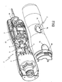
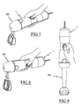
- FIG. 1 shows an appliance housing 1 comprising an elongated body whose longitudinal end is intended to be coupled to an accessory, such as a mixer accessory 100 or a mixing stand 200, shown in FIGS. 7 to 9.
- an accessory such as a mixer accessory 100 or a mixing stand 200, shown in FIGS. 7 to 9.
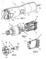
- the casing 1 comprises a body of circular section constituted by two shells 10 assembled one on the other and comprises a manual gripping zone having a maximum section near the longitudinal ends of the casing 1 and a restricted section in the central part of the casing 1.
- the end of the housing 1 intended to be coupled to the accessory has four threads 11 quarter turn regularly distributed over the periphery of the shells 10 which allow the coupling by screwing the accessory in four orientations offset 90 °.
- the locking in position of the accessory on the housing 1 is provided by a locking device 9 having teeth 90 resiliently projecting outside the body of the housing 1, these teeth 90 being intended to cooperate with ribs formed on the housing. 'accessory.
- the locking device 9 also comprises an unlocking button 91 which, when depressed, allows the teeth 90 to be erased inside the body of the casing 1.
- the rear end 1B of the casing for its part, has an opening for the passage of a power cord 12.
- the housing 1 encloses a motor 2 whose output shaft 20 is connected to the drive shaft 30 of a gearbox 3 having at its output a rotary gear train 31 with two speeds arranged opposite an opening 13 made in the partition closing the front end 1A of the housing.
- the motor 2 is disposed in the part of the housing 1 near the rear end 1B, the housing 1 having at this location a diameter slightly greater than the outside diameter of the engine 2 so that there is a slight gap between the engine 2 and the housing body 1 allowing the circulation of a flow of air.
- the motor 2 is arranged along the longitudinal axis of the housing 1 and is held by means of a damping element 4 on lugs 14 of the body of the housing 1, the motor 2 being preferably spaced from the gear 3 by more than 10 mm .
- the damping element 4, shown alone in FIG. 6, consists of two end elements 41 connected to each other by elastic links 42, the two end elements 41 being placed at the ends of the engine 2 and held thereon. by the elastic deformation of connections 41.
- the gearbox 3 is disposed in the part of the housing near the front end 1A, the housing 1 having at this location a diameter slightly greater than the outer diameter of the gearbox 3 so that there is a slight gap between the gearbox 3 and the body of the housing 1 allowing the circulation of a flow of air.
- the immobilization of the gearbox 3 is achieved by lugs 15 of the body of the casing 1 and the drive shaft 30 of the gearbox is preferably connected to the output shaft 20 of the motor by means of a universal joint 5 providing a flexible connection allowing misalignment between the drive shaft 30 of the gearbox and the output shaft 20 of the motor.
- This universal joint 5, shown disassembled in FIG. 5, is for example constituted by a ring 51, integral with the output shaft 20 of the engine, comprising grooves 52 in which are engaged flats 53 carried by the end of the drive shaft 30.
- the operation of the engine 2 is controlled by a switch 6 disposed next to the cardan shaft 5, in the free space existing between the motor 2 and the gearbox 3.
- the switch 6 is actuated by a control button 7 disposed at the level of the central portion of the housing 1 having a restricted section, the housing 1 having at this location an impression 16 adapted to the shape of a thumb whose bottom is formed by the actuating surface 70 of the control knob 7.
- the control button 7 acts on the switch 6 via an actuating member 71 extending laterally above the switch 6 and comprises slideways 72 cooperating with guide rails 17 carried by the one of the shells 10 of the housing 1 for guiding the control knob 7 in translation.
- the housing 1 is provided with a fan 8 integral with the drive shaft 30 of the gearbox 3 and disposed near the reducer 3, downstream of the control button 7.
- the fan 8 consists of a disk 80 provided with blades 81 on its two faces, the blades 81 adjacent to the reducer 3 driving the air around the latter in the direction the front end 1A of the housing, games being provided at the unlocking button 13 to allow the escape of the air flow generated by the fan 8.
- the blades 81 facing the engine 2 are in turn juxtaposed to a flange 18 carried by the shells 10 and cooperate with the flange 18 to suck the air on the side of the engine 2 through a central opening of the flange 18 , thus generating a depression in the central part of the body of the casing 1 and the admission of fresh air through games provided at the junction between a piece overmoulding of the cord 12 and the shells 10 of the casing 1.
- Such an arrangement of the fan 8 has the advantage of generating, inside the casing 1, a flow of air flowing from the overmoulding piece 19 of the cord 12 towards the unlocking button 90 which ensures the cooling of the motor 2 and reducer 3 without hot air delivery at the control knob 7.
- FIGS. 7 and 8 illustrate the ergonomic advantages of use of the housing according to the invention according to the accessory used.
- the housing described above can be comfortably used in a horizontal position while being coupled to a drummer accessory 100.
- the user can adopt an ergonomic position by applying the inch to the height of the control button 7 and placing his hand straddling the central area and the rear part of the housing 1.
- the substantially balanced distribution of the masses around the control knob 7 obtained through the distribution of the engine and the reducer around the control button 7 contributes to the comfort of use.
- FIGS. 7 and 8 respectively illustrate, by way of examples, the use of the housing with the control button facing up and to the side.
- the control button can also be turned down if the user prefers to use the index finger or another finger, to operate the command button.
- Such a device also has the advantage of providing the same ergonomics of use for right-handed and left-handed users.
- the housing according to the invention may also be comfortably used in a vertical position, for example being coupled with a mixing stand 200.
- the housing according to the invention can be used with any type of accessory other than those previously described.
Landscapes
- Engineering & Computer Science (AREA)
- Mechanical Engineering (AREA)
- Food Science & Technology (AREA)
- Food-Manufacturing Devices (AREA)
- Structures Of Non-Positive Displacement Pumps (AREA)
- Cookers (AREA)
- Motor Or Generator Frames (AREA)
- Packages (AREA)
Claims (12)
- Gehäuse (1) für ein Elektrohaushaltsgerät zur Nahrungszubereitung, mit einem Motor (2), der mit einem Reduktionsgetriebe (3) angekoppelt ist, das mit einem drehenden Mitnehmer (31) versehen ist, der gegenüber einer an einem Längsende (1A) des Gehäuses (1) vorgesehenen Öffnung (13) angeordnet ist, wobei das Längsende (1A) mit Mitteln zum Ankoppeln an einem Rührzubehör (100) oder Mixstab (200) versehen ist, wobei das Gehäuse dazu vorgesehen ist, je nach verwendetem Zubehör waagerecht oder senkrecht gehalten zu werden, und einen Körper aufweist, der einen langgestreckten Bereich zum Halten mit der Hand umfasst, wobei der Körper den Motor (2) und das Reduktionsgetriebe (3) einschließt, und der Betrieb des Motors (2) über einen vom Gehäuse (1) getragenen Betätigungsknopf (7) gesteuert wird, dadurch gekennzeichnet, dass der Motor (2) und das Reduktionsgetriebe (3) voneinander beabstandet sind und dass der Betätigungsknopf (7) längs an dem Bereich des Gehäuses (1) liegt, der zwischen dem Motor (2) und dem Reduktionsgetriebe angeordnet ist, so dass auf der einen und anderen Seite des Betätigungsknopf (7) ein Bereich zum Greifen des Gehäuses (1) an dem den Motor (2) und das Reduktionsgetriebe (3) einschließenden Körper eingebracht ist.
- Gehäuse für Elektrohaushaltsgerät nach Anspruch 1, dadurch gekennzeichnet, dass der Körper des Gehäuses (1) einen verringerten Querschnitt an der Stelle aufweist, an der sich der Betätigungsknopf (7) befindet.
- Gehäuse für Elektrohaushaltsgerät nach einem der Ansprüche 1 bi 2, dadurch gekennzeichnet, dass der Motor (2) und das Reduktionsgetriebe (3) an den beiden entgegengesetzten Längsenden (A1, 1B) des Gehäuses (1) angeordnet sind, wobei der Betätigungsknopf (7) im wesentlichen im mittleren Bereich des Gehäuses (1) angeordnet ist.
- Gehäuse für Elektrohaushaltsgerät nach einem der Ansprüche 2 bis 3, dadurch gekennzeichnet, dass der Betätigungsknopf (7) des Motors (2) mit einem Schalter (6) zusammenwirkt, der zwischen dem Motor (2) und dem Reduktionsgetriebe (3) angeordnet ist.
- Gehäuse für Elektrohaushaltsgerät nach einem der Ansprüche 2 bis 4, dadurch gekennzeichnet, dass der Motor (2) eine Abtriebwelle (20) aufweist, die mit einer Antriebswelle (30) des Reduktionsgetriebes (3) mittels eines Kardangelenks (5) verbunden ist, das eine elastische Verbindung zwischen der Abtriebwelle (20) und der Antriebswelle (30) gewährleistet.
- Gehäuse für Elektrohaushaltsgerät nach einem der Ansprüche 1 bis 5, dadurch gekennzeichnet, dass die Mittel zum Ankoppeln an das Zubehör (100; 200) Vierteldrehungsgewinde (11), die das Einschrauben des Zubehörs auf den Körper des Gehäuses (1) entlang vier Stellungen ermöglichen, welche gegeneinander um 90° versetzt sind, sowie ein automatisches (9) Verriegelungssystem (9) aufweisen, das einen Entriegelungsknopf (91) umfasst, um das Zubehör (100; 200) zu lösen.
- Gehäuse für Elektrohaushaltsgerät nach einem der Ansprüche 2 bis 6, dadurch gekennzeichnet, dass der Motor (2) und das Reduktionsgetriebe (3) über einen Lüfter (8) gekühlt sind, der von der Antriebswelle (30) des Reduktionsgetriebes (3) getragen ist und sich zwischen dem Reduktionsgetriebe (3) und dem Betätigungsknopf (7) befindet, wobei der Lüfter (8) im Körper des Gehäuses (1) eine Luftströmung erzeugt, die am Betätigungsknopf einen Unterdruck bildet.
- Gehäuse für Elektrohaushaltsgerät nach Anspruch 7, dadurch gekennzeichnet, dass der Lüfter (8) aus einer Scheibe (80) besteht, die zwei Flügel (81) an ihren beiden Seiten aufweist, und dass das Gehäuse (1) eine Wange (18) zum Leiten des Luftstroms in die Nähe der zum Motor (2) ausgerichteten Flügel (81) aufweist.
- Gehäuse für Elektrohaushaltsgerät nach einem der Ansprüche 6 und 8, dadurch gekennzeichnet, dass der Entriegelungsknopf (91) in der Nähe desjenigen Endes (1A) des Gehäuses angeordnet ist, das mit den Ankopplungsmitteln versehen ist, wobei der vom Lüfter erzeugte Luftstrom durch ein zwischen dem Entriegelungsknopf (91) und dem Körper des Gehäuses (1) vorgesehenes Spiel hindurch entweicht.
- Gehäuse für Elektrohaushaltsgerät nach einem der Ansprüche 7 bis 9, dadurch gekennzeichnet, dass der Motor (2) über eine Netzschnur (12) versorgt wird, die durch eine Öffnung hindurchgeht, die in dem dem Ende (1A) entgegengesetzten Längsende (1B) des Gehäuses eingebracht ist, das die Mittel zum Ankoppeln an das Zubehör aufweist, und dass an der Verbindung zwischen der Netzschnur (12) und dem Körper des Gehäuses (1) ein Spiel vorgesehen ist, das beim Betrieb des Lüfters das Einströmen von Luft in den Körper des Gehäuses (1) ermöglicht.
- Gehäuse für Elektrohaushaltsgerät nach einem der Ansprüche 1 bis 10, dadurch gekennzeichnet, dass ein Dämpfmittel (4) zwischen dem Motor (2) und dem Körper des Gehäuses (1) eingesetzt ist, wobei das Dämpfmittel (4) endseitige Elemente (41) aufweisen, die an jedem Längsende des Motors (2) angeordnet und über elastische Verbindungsarme (42) miteinander verbunden sind.
- Elektrohaushaltsgerät zur Nahrungszubereitung mit einem Motor, dem ein Zubehör, wie ein Mixstab (200) oder ein Rührzubehör (100) zugeordnet ist, dadurch gekennzeichnet, dass es ein Gehäuse (1) nach einem der Ansprüche 1 bis 11 aufweist.
Applications Claiming Priority (2)
| Application Number | Priority Date | Filing Date | Title |
|---|---|---|---|
| FR0312918A FR2861568B1 (fr) | 2003-11-04 | 2003-11-04 | Boitier d'appareil electromenager de preparation culinaire prevu pour etre tenu a la main selon differentes positions |
| FR0312918 | 2003-11-04 |
Publications (2)
| Publication Number | Publication Date |
|---|---|
| EP1529473A1 EP1529473A1 (de) | 2005-05-11 |
| EP1529473B1 true EP1529473B1 (de) | 2007-05-23 |
Family
ID=34429875
Family Applications (1)
| Application Number | Title | Priority Date | Filing Date |
|---|---|---|---|
| EP04356162A Expired - Lifetime EP1529473B1 (de) | 2003-11-04 | 2004-10-08 | In verschiedenen Positionen haltbares Gehäuse für elektrisches Haushaltsgerät zur Nahrungszubereitung |
Country Status (6)
| Country | Link |
|---|---|
| EP (1) | EP1529473B1 (de) |
| CN (1) | CN100531637C (de) |
| AT (1) | ATE362724T1 (de) |
| DE (1) | DE602004006581D1 (de) |
| ES (1) | ES2286576T3 (de) |
| FR (1) | FR2861568B1 (de) |
Cited By (2)
| Publication number | Priority date | Publication date | Assignee | Title |
|---|---|---|---|---|
| US12201242B2 (en) | 2021-02-04 | 2025-01-21 | Black & Decker, Inc. | Modular hand-held kitchen applicance |
| US12262849B2 (en) | 2021-02-04 | 2025-04-01 | Black & Decker, Inc. | Modular hand-held kitchen applicance |
Families Citing this family (9)
| Publication number | Priority date | Publication date | Assignee | Title |
|---|---|---|---|---|
| WO2007007448A1 (ja) * | 2005-07-07 | 2007-01-18 | Matsushita Electric Industrial Co., Ltd. | フードプロセッサー |
| FR2910260B1 (fr) * | 2006-12-22 | 2009-01-23 | Seb Sa | Boite de rangement pour mixer menager de type plongeant. |
| EP2198761A1 (de) * | 2008-12-18 | 2010-06-23 | Koninklijke Philips Electronics N.V. | Abgabesystem für ein Küchenutensil |
| FR2954079B1 (fr) * | 2009-12-18 | 2012-07-27 | Seb Sa | Appareil electromenager de preparation culinaire prevu pour etre tenu a la main muni d'un dispositif de commande particulier |
| FR2977785B1 (fr) * | 2011-07-13 | 2013-07-05 | Seb Sa | Appareil electromenager de preparation culinaire comportant un dispositif presse-puree |
| FR2977784B1 (fr) | 2011-07-13 | 2013-07-12 | Seb Sa | Grille de dispositif presse-puree et appareil electromenager de preparation culinaire comportant une telle grille |
| KR101448464B1 (ko) * | 2013-11-29 | 2014-10-13 | 김순련 | 분리형 핸드믹서 |
| FR3083688B1 (fr) * | 2018-07-13 | 2020-06-19 | Seb S.A. | Systeme de ventilation d'un appareil electro-menager portatif de traitement de preparations alimentaires, de type mixeur / batteur |
| CN112369940A (zh) * | 2020-10-23 | 2021-02-19 | 青岛汉尚电器有限公司 | 一种手持式打蛋装置 |
Family Cites Families (8)
| Publication number | Priority date | Publication date | Assignee | Title |
|---|---|---|---|---|
| US2048455A (en) * | 1934-12-12 | 1936-07-21 | Dominion Electrical Mfg Co | Food mixing device with beater ejector |
| US2707623A (en) * | 1952-11-12 | 1955-05-03 | Dormeyer Corp | Portable food mixer |
| FR1303638A (fr) | 1961-08-04 | 1962-09-14 | Expl Chimie Et Mecanique E C E | Groupe batteur-réducteur adaptable sur mixer |
| FR2537424B1 (fr) * | 1982-12-09 | 1987-07-24 | Moulinex Sa | Appareil electromenager, tel qu'un mixeur, equipe d'un accessoire batteur amovible |
| US4856718A (en) | 1987-12-04 | 1989-08-15 | Better Mousetraps Inc. | Food processor and food cutting devices therefor |
| DE19635223A1 (de) * | 1996-08-30 | 1998-03-05 | Bosch Siemens Hausgeraete | Stabmixer mit Fußteil |
| ES2190714B1 (es) * | 2000-12-05 | 2004-04-01 | Cristobal Lozano Fernandez | Boquilla de limpieza de flujo controlado. |
| CN2520806Y (zh) * | 2001-09-19 | 2002-11-20 | 东莞市联创电器有限公司 | 多功能食物搅拌机 |
-
2003
- 2003-11-04 FR FR0312918A patent/FR2861568B1/fr not_active Expired - Fee Related
-
2004
- 2004-10-08 AT AT04356162T patent/ATE362724T1/de not_active IP Right Cessation
- 2004-10-08 ES ES04356162T patent/ES2286576T3/es not_active Expired - Lifetime
- 2004-10-08 DE DE602004006581T patent/DE602004006581D1/de not_active Expired - Lifetime
- 2004-10-08 EP EP04356162A patent/EP1529473B1/de not_active Expired - Lifetime
- 2004-11-03 CN CNB2004100883627A patent/CN100531637C/zh not_active Expired - Fee Related
Non-Patent Citations (1)
| Title |
|---|
| None * |
Cited By (2)
| Publication number | Priority date | Publication date | Assignee | Title |
|---|---|---|---|---|
| US12201242B2 (en) | 2021-02-04 | 2025-01-21 | Black & Decker, Inc. | Modular hand-held kitchen applicance |
| US12262849B2 (en) | 2021-02-04 | 2025-04-01 | Black & Decker, Inc. | Modular hand-held kitchen applicance |
Also Published As
| Publication number | Publication date |
|---|---|
| CN1613415A (zh) | 2005-05-11 |
| ES2286576T3 (es) | 2007-12-01 |
| EP1529473A1 (de) | 2005-05-11 |
| ATE362724T1 (de) | 2007-06-15 |
| CN100531637C (zh) | 2009-08-26 |
| FR2861568A1 (fr) | 2005-05-06 |
| DE602004006581D1 (de) | 2007-07-05 |
| FR2861568B1 (fr) | 2005-12-30 |
Similar Documents
| Publication | Publication Date | Title |
|---|---|---|
| EP1529473B1 (de) | In verschiedenen Positionen haltbares Gehäuse für elektrisches Haushaltsgerät zur Nahrungszubereitung | |
| WO2000073662A1 (fr) | Ventilateur equipe d'une manche a air | |
| FR2508952A1 (fr) | Appareil de balayage portable | |
| WO2007042635A1 (fr) | Pied de mixage et mixeur menager de type plongeant muni d'un tel pied de mixage | |
| WO2012136906A2 (fr) | Souffleur electroportatif autonome a vitesse de sortie d'air modulable | |
| FR2669850A1 (fr) | Debroussailleuse equipee d'un arbre mene monte dans un tube protecteur entre la tete de coupe et le moteur de commande. | |
| FR3130524A1 (fr) | Appareil de coiffure comprenant un module de soufflerie ameliore a helices contrarotatives | |
| FR3109515A1 (fr) | Unité de nettoyage pour tête d’aspiration | |
| FR2920406A3 (fr) | Appareil de propulsion actionne manuellement | |
| FR3083688A1 (fr) | Systeme de ventilation d'un appareil electro-menager portatif de traitement de preparations alimentaires, de type mixeur / batteur | |
| FR2771784A1 (fr) | Tete de renvoi reglable, notamment pour un accessoire taille-haies | |
| EP3079544B1 (de) | Haushaltsgerät zur lebensmittelzubereitung mit einem unterem arm an einem sockel und einem oberem arm, der über scharniere mit dem unteren arm verbunden ist | |
| CA3200235A1 (fr) | Boitier d'appareil electromenager de preparation culinaire multifonctions tenu a la main | |
| FR2905584A1 (fr) | Mixeur menager de type plongeant comportant un outil de travail presentant la forme d'une vis d'archimede. | |
| EP1529472A1 (de) | Elektrisches Haushaltsgerät zur Nahrungszubereitung mit einer lösbar an einem Gehäuse gekoppelten Zusatzvorrichtung | |
| WO2015086968A1 (fr) | Appareil electromenager de preparation culinaire comportant un socle, un bras inferieur et un bras superieur monte pivotant sur le bras inferieur | |
| FR2945432A1 (fr) | Appareil electromenager de preparation culinaire comportant un recipient de travail en contact thermique avec un element chauffant | |
| EP3079542B1 (de) | Haushaltsgerät zur lebensmittelzubereitung mit einem unterem arm an einem sockel und einem oberem arm, der über scharniere mit dem unteren arm verbunden ist | |
| EP1604598B1 (de) | Haltbares Gehäuse für elektrisches Haushaltsgerät zur Nahrungszubereitung | |
| FR2775921A1 (fr) | Instrument de travail guide manuellement et comportant un arbre de transmission tournant dans un palier lisse d'un tube de protection | |
| FR2910260A1 (fr) | Boite de rangement pour mixer menager de type plongeant. | |
| EP3079543B1 (de) | Haushaltsgerät zur lebensmittelzubereitung mit einem sockel, einem unter arm und einem oberem arm, die über scharniere miteinander verbunden sind | |
| FR2861567A1 (fr) | Appareil electromenager comportant un boitier renfermant un moteur reposant sur le boitier par l'intermediaire d'elements amortisseur | |
| FR3158030A1 (fr) | Appareil de préparation culinaire équipé d’un système de cuisson à air chaud et d’une pale de brassage | |
| FR2686009A1 (fr) | Batteur-mixeur electrique a main. |
Legal Events
| Date | Code | Title | Description |
|---|---|---|---|
| PUAI | Public reference made under article 153(3) epc to a published international application that has entered the european phase |
Free format text: ORIGINAL CODE: 0009012 |
|
| AK | Designated contracting states |
Kind code of ref document: A1 Designated state(s): AT BE BG CH CY CZ DE DK EE ES FI FR GB GR HU IE IT LI LU MC NL PL PT RO SE SI SK TR |
|
| AX | Request for extension of the european patent |
Extension state: AL HR LT LV MK |
|
| 17P | Request for examination filed |
Effective date: 20051108 |
|
| AKX | Designation fees paid |
Designated state(s): AT BE BG CH CY CZ DE DK EE ES FI FR GB GR HU IE IT LI LU MC NL PL PT RO SE SI SK TR |
|
| 17Q | First examination report despatched |
Effective date: 20060406 |
|
| GRAP | Despatch of communication of intention to grant a patent |
Free format text: ORIGINAL CODE: EPIDOSNIGR1 |
|
| GRAS | Grant fee paid |
Free format text: ORIGINAL CODE: EPIDOSNIGR3 |
|
| GRAA | (expected) grant |
Free format text: ORIGINAL CODE: 0009210 |
|
| AK | Designated contracting states |
Kind code of ref document: B1 Designated state(s): AT BE BG CH CY CZ DE DK EE ES FI FR GB GR HU IE IT LI LU MC NL PL PT RO SE SI SK TR |
|
| PG25 | Lapsed in a contracting state [announced via postgrant information from national office to epo] |
Ref country code: FI Free format text: LAPSE BECAUSE OF FAILURE TO SUBMIT A TRANSLATION OF THE DESCRIPTION OR TO PAY THE FEE WITHIN THE PRESCRIBED TIME-LIMIT Effective date: 20070523 |
|
| REG | Reference to a national code |
Ref country code: GB Ref legal event code: FG4D Free format text: NOT ENGLISH |
|
| REG | Reference to a national code |
Ref country code: CH Ref legal event code: EP |
|
| REG | Reference to a national code |
Ref country code: IE Ref legal event code: FG4D Free format text: LANGUAGE OF EP DOCUMENT: FRENCH |
|
| REF | Corresponds to: |
Ref document number: 602004006581 Country of ref document: DE Date of ref document: 20070705 Kind code of ref document: P |
|
| GBT | Gb: translation of ep patent filed (gb section 77(6)(a)/1977) |
Effective date: 20070628 |
|
| PG25 | Lapsed in a contracting state [announced via postgrant information from national office to epo] |
Ref country code: SE Free format text: LAPSE BECAUSE OF FAILURE TO SUBMIT A TRANSLATION OF THE DESCRIPTION OR TO PAY THE FEE WITHIN THE PRESCRIBED TIME-LIMIT Effective date: 20070823 |
|
| NLV1 | Nl: lapsed or annulled due to failure to fulfill the requirements of art. 29p and 29m of the patents act | ||
| PG25 | Lapsed in a contracting state [announced via postgrant information from national office to epo] |
Ref country code: AT Free format text: LAPSE BECAUSE OF FAILURE TO SUBMIT A TRANSLATION OF THE DESCRIPTION OR TO PAY THE FEE WITHIN THE PRESCRIBED TIME-LIMIT Effective date: 20070523 Ref country code: PL Free format text: LAPSE BECAUSE OF FAILURE TO SUBMIT A TRANSLATION OF THE DESCRIPTION OR TO PAY THE FEE WITHIN THE PRESCRIBED TIME-LIMIT Effective date: 20070523 |
|
| REG | Reference to a national code |
Ref country code: ES Ref legal event code: FG2A Ref document number: 2286576 Country of ref document: ES Kind code of ref document: T3 |
|
| REG | Reference to a national code |
Ref country code: IE Ref legal event code: FD4D |
|
| PG25 | Lapsed in a contracting state [announced via postgrant information from national office to epo] |
Ref country code: BG Free format text: LAPSE BECAUSE OF FAILURE TO SUBMIT A TRANSLATION OF THE DESCRIPTION OR TO PAY THE FEE WITHIN THE PRESCRIBED TIME-LIMIT Effective date: 20070823 Ref country code: CZ Free format text: LAPSE BECAUSE OF FAILURE TO SUBMIT A TRANSLATION OF THE DESCRIPTION OR TO PAY THE FEE WITHIN THE PRESCRIBED TIME-LIMIT Effective date: 20070523 Ref country code: NL Free format text: LAPSE BECAUSE OF FAILURE TO SUBMIT A TRANSLATION OF THE DESCRIPTION OR TO PAY THE FEE WITHIN THE PRESCRIBED TIME-LIMIT Effective date: 20070523 Ref country code: PT Free format text: LAPSE BECAUSE OF FAILURE TO SUBMIT A TRANSLATION OF THE DESCRIPTION OR TO PAY THE FEE WITHIN THE PRESCRIBED TIME-LIMIT Effective date: 20071023 Ref country code: DK Free format text: LAPSE BECAUSE OF FAILURE TO SUBMIT A TRANSLATION OF THE DESCRIPTION OR TO PAY THE FEE WITHIN THE PRESCRIBED TIME-LIMIT Effective date: 20070523 Ref country code: IE Free format text: LAPSE BECAUSE OF FAILURE TO SUBMIT A TRANSLATION OF THE DESCRIPTION OR TO PAY THE FEE WITHIN THE PRESCRIBED TIME-LIMIT Effective date: 20070523 Ref country code: SI Free format text: LAPSE BECAUSE OF FAILURE TO SUBMIT A TRANSLATION OF THE DESCRIPTION OR TO PAY THE FEE WITHIN THE PRESCRIBED TIME-LIMIT Effective date: 20070523 |
|
| PG25 | Lapsed in a contracting state [announced via postgrant information from national office to epo] |
Ref country code: SK Free format text: LAPSE BECAUSE OF FAILURE TO SUBMIT A TRANSLATION OF THE DESCRIPTION OR TO PAY THE FEE WITHIN THE PRESCRIBED TIME-LIMIT Effective date: 20070523 |
|
| PLBE | No opposition filed within time limit |
Free format text: ORIGINAL CODE: 0009261 |
|
| STAA | Information on the status of an ep patent application or granted ep patent |
Free format text: STATUS: NO OPPOSITION FILED WITHIN TIME LIMIT |
|
| 26N | No opposition filed |
Effective date: 20080226 |
|
| BERE | Be: lapsed |
Owner name: SEB S.A. Effective date: 20071031 |
|
| PG25 | Lapsed in a contracting state [announced via postgrant information from national office to epo] |
Ref country code: DE Free format text: LAPSE BECAUSE OF FAILURE TO SUBMIT A TRANSLATION OF THE DESCRIPTION OR TO PAY THE FEE WITHIN THE PRESCRIBED TIME-LIMIT Effective date: 20070824 Ref country code: GR Free format text: LAPSE BECAUSE OF FAILURE TO SUBMIT A TRANSLATION OF THE DESCRIPTION OR TO PAY THE FEE WITHIN THE PRESCRIBED TIME-LIMIT Effective date: 20070824 |
|
| PG25 | Lapsed in a contracting state [announced via postgrant information from national office to epo] |
Ref country code: MC Free format text: LAPSE BECAUSE OF NON-PAYMENT OF DUE FEES Effective date: 20071031 Ref country code: RO Free format text: LAPSE BECAUSE OF FAILURE TO SUBMIT A TRANSLATION OF THE DESCRIPTION OR TO PAY THE FEE WITHIN THE PRESCRIBED TIME-LIMIT Effective date: 20070523 |
|
| PG25 | Lapsed in a contracting state [announced via postgrant information from national office to epo] |
Ref country code: BE Free format text: LAPSE BECAUSE OF NON-PAYMENT OF DUE FEES Effective date: 20071031 |
|
| REG | Reference to a national code |
Ref country code: FR Ref legal event code: ST Effective date: 20080630 |
|
| PG25 | Lapsed in a contracting state [announced via postgrant information from national office to epo] |
Ref country code: EE Free format text: LAPSE BECAUSE OF FAILURE TO SUBMIT A TRANSLATION OF THE DESCRIPTION OR TO PAY THE FEE WITHIN THE PRESCRIBED TIME-LIMIT Effective date: 20070523 |
|
| PG25 | Lapsed in a contracting state [announced via postgrant information from national office to epo] |
Ref country code: FR Free format text: LAPSE BECAUSE OF NON-PAYMENT OF DUE FEES Effective date: 20071031 |
|
| REG | Reference to a national code |
Ref country code: CH Ref legal event code: PL |
|
| PG25 | Lapsed in a contracting state [announced via postgrant information from national office to epo] |
Ref country code: CY Free format text: LAPSE BECAUSE OF FAILURE TO SUBMIT A TRANSLATION OF THE DESCRIPTION OR TO PAY THE FEE WITHIN THE PRESCRIBED TIME-LIMIT Effective date: 20070523 |
|
| PG25 | Lapsed in a contracting state [announced via postgrant information from national office to epo] |
Ref country code: LU Free format text: LAPSE BECAUSE OF NON-PAYMENT OF DUE FEES Effective date: 20071008 |
|
| PG25 | Lapsed in a contracting state [announced via postgrant information from national office to epo] |
Ref country code: TR Free format text: LAPSE BECAUSE OF FAILURE TO SUBMIT A TRANSLATION OF THE DESCRIPTION OR TO PAY THE FEE WITHIN THE PRESCRIBED TIME-LIMIT Effective date: 20070523 Ref country code: HU Free format text: LAPSE BECAUSE OF FAILURE TO SUBMIT A TRANSLATION OF THE DESCRIPTION OR TO PAY THE FEE WITHIN THE PRESCRIBED TIME-LIMIT Effective date: 20071124 |
|
| PG25 | Lapsed in a contracting state [announced via postgrant information from national office to epo] |
Ref country code: LI Free format text: LAPSE BECAUSE OF NON-PAYMENT OF DUE FEES Effective date: 20081031 Ref country code: CH Free format text: LAPSE BECAUSE OF NON-PAYMENT OF DUE FEES Effective date: 20081031 |
|
| PGFP | Annual fee paid to national office [announced via postgrant information from national office to epo] |
Ref country code: GB Payment date: 20131010 Year of fee payment: 10 |
|
| PGFP | Annual fee paid to national office [announced via postgrant information from national office to epo] |
Ref country code: ES Payment date: 20131018 Year of fee payment: 10 Ref country code: IT Payment date: 20131014 Year of fee payment: 10 |
|
| GBPC | Gb: european patent ceased through non-payment of renewal fee |
Effective date: 20141008 |
|
| PG25 | Lapsed in a contracting state [announced via postgrant information from national office to epo] |
Ref country code: GB Free format text: LAPSE BECAUSE OF NON-PAYMENT OF DUE FEES Effective date: 20141008 |
|
| PG25 | Lapsed in a contracting state [announced via postgrant information from national office to epo] |
Ref country code: IT Free format text: LAPSE BECAUSE OF NON-PAYMENT OF DUE FEES Effective date: 20141008 |
|
| REG | Reference to a national code |
Ref country code: ES Ref legal event code: FD2A Effective date: 20151126 |
|
| PG25 | Lapsed in a contracting state [announced via postgrant information from national office to epo] |
Ref country code: ES Free format text: LAPSE BECAUSE OF NON-PAYMENT OF DUE FEES Effective date: 20141009 |