EP1529473B1 - Housing for electrical household cooking appliance designed to be hand-held in different positions - Google Patents
Housing for electrical household cooking appliance designed to be hand-held in different positions Download PDFInfo
- Publication number
- EP1529473B1 EP1529473B1 EP04356162A EP04356162A EP1529473B1 EP 1529473 B1 EP1529473 B1 EP 1529473B1 EP 04356162 A EP04356162 A EP 04356162A EP 04356162 A EP04356162 A EP 04356162A EP 1529473 B1 EP1529473 B1 EP 1529473B1
- Authority
- EP
- European Patent Office
- Prior art keywords
- housing
- motor
- household electrical
- electrical appliance
- gearbox
- Prior art date
- Legal status (The legal status is an assumption and is not a legal conclusion. Google has not performed a legal analysis and makes no representation as to the accuracy of the status listed.)
- Not-in-force
Links
Images

Classifications
-
- A—HUMAN NECESSITIES
- A47—FURNITURE; DOMESTIC ARTICLES OR APPLIANCES; COFFEE MILLS; SPICE MILLS; SUCTION CLEANERS IN GENERAL
- A47J—KITCHEN EQUIPMENT; COFFEE MILLS; SPICE MILLS; APPARATUS FOR MAKING BEVERAGES
- A47J43/00—Implements for preparing or holding food, not provided for in other groups of this subclass
- A47J43/04—Machines for domestic use not covered elsewhere, e.g. for grinding, mixing, stirring, kneading, emulsifying, whipping or beating foodstuffs, e.g. power-driven
- A47J43/06—Machines for domestic use not covered elsewhere, e.g. for grinding, mixing, stirring, kneading, emulsifying, whipping or beating foodstuffs, e.g. power-driven with a plurality of interchangeable working units, e.g. with a single driving-unit
-
- A—HUMAN NECESSITIES
- A47—FURNITURE; DOMESTIC ARTICLES OR APPLIANCES; COFFEE MILLS; SPICE MILLS; SUCTION CLEANERS IN GENERAL
- A47J—KITCHEN EQUIPMENT; COFFEE MILLS; SPICE MILLS; APPARATUS FOR MAKING BEVERAGES
- A47J43/00—Implements for preparing or holding food, not provided for in other groups of this subclass
- A47J43/04—Machines for domestic use not covered elsewhere, e.g. for grinding, mixing, stirring, kneading, emulsifying, whipping or beating foodstuffs, e.g. power-driven
- A47J43/07—Parts or details, e.g. mixing tools, whipping tools
- A47J43/08—Driving mechanisms
- A47J43/082—Driving mechanisms for machines with tools driven from the upper side
-
- A—HUMAN NECESSITIES
- A47—FURNITURE; DOMESTIC ARTICLES OR APPLIANCES; COFFEE MILLS; SPICE MILLS; SUCTION CLEANERS IN GENERAL
- A47J—KITCHEN EQUIPMENT; COFFEE MILLS; SPICE MILLS; APPARATUS FOR MAKING BEVERAGES
- A47J43/00—Implements for preparing or holding food, not provided for in other groups of this subclass
- A47J43/04—Machines for domestic use not covered elsewhere, e.g. for grinding, mixing, stirring, kneading, emulsifying, whipping or beating foodstuffs, e.g. power-driven
- A47J43/044—Machines for domestic use not covered elsewhere, e.g. for grinding, mixing, stirring, kneading, emulsifying, whipping or beating foodstuffs, e.g. power-driven with tools driven from the top side
- A47J2043/04409—Apparatus of hand held type
- A47J2043/04418—Apparatus of hand held type with housing extending perpendicular, e.g. horizontally, from the tool axis
-
- A—HUMAN NECESSITIES
- A47—FURNITURE; DOMESTIC ARTICLES OR APPLIANCES; COFFEE MILLS; SPICE MILLS; SUCTION CLEANERS IN GENERAL
- A47J—KITCHEN EQUIPMENT; COFFEE MILLS; SPICE MILLS; APPARATUS FOR MAKING BEVERAGES
- A47J43/00—Implements for preparing or holding food, not provided for in other groups of this subclass
- A47J43/04—Machines for domestic use not covered elsewhere, e.g. for grinding, mixing, stirring, kneading, emulsifying, whipping or beating foodstuffs, e.g. power-driven
- A47J43/044—Machines for domestic use not covered elsewhere, e.g. for grinding, mixing, stirring, kneading, emulsifying, whipping or beating foodstuffs, e.g. power-driven with tools driven from the top side
- A47J2043/04409—Apparatus of hand held type
- A47J2043/04427—Apparatus of hand held type with housing extending vertically in line with the tool axis
Definitions
- the present invention relates to the general technical field of household appliances for culinary preparation held by hand.
- the present invention relates more particularly to devices comprising a housing whose one end can be coupled to different types of accessories, such as a mixing stand or a drumming attachment, and for which the housing can be held vertically or horizontally depending on the accessory used.
- Document FR 1 303 638 discloses an appliance with an elongated cylindrical housing incorporating a motor whose output shaft opens at a longitudinal end of the housing that can be interchangeably connected to a mixing stand or a beater accessory.
- Such an apparatus comprises a motor control button which is disposed near the end of the housing opposite the end coupled to the accessory, such an arrangement allowing easy manipulation of the button with the thumb when the housing is used vertically. with the mixing foot.
- a location of the control button is unsuitable for horizontal use of the housing with the mixer accessory, the control knob being then opposite the thumb of the hand holding the device.
- an electrical appliance for culinary preparation comprising an elongate cylindrical housing incorporating a motor and a gearbox, a longitudinal end of which can be coupled to various accessories.
- Such an apparatus comprises a motor control button placed on a protrusion of the housing disposed at the height of the gearbox, near the end of the housing coupled to the accessory.
- a location allows easy manipulation of the control button with the thumb when the housing is held horizontally but is not suitable for vertical use of the housing.
- the location of the control button on a protrusion of the housing causes an uncomfortable thumb position favoring tension.
- the following invention aims to overcome these disadvantages by providing a housing appliance providing great ergonomics of use, particularly in the handling of the engine control button, the housing is held vertically or horizontally.
- the invention also aims to provide an appliance housing providing a good balance of masses relative to the gripping area when the housing is held horizontally.
- the object of the invention is achieved by a household appliance housing for culinary preparation according to claim 1.
- Such a combination of features makes it possible, while maintaining a reduced length of the casing, to provide a longitudinal longitudinal zone of a large grip on either side of the control button, making it easier to grip during vertical or horizontal use of the casing.
- such a characteristic also makes it possible to obtain a good balance of masses with respect to the control button when the casing is used horizontally.
- the body of the housing has a restricted cross section at the location of the control button.
- the motor and the gearbox are arranged at the two opposite longitudinal ends of the housing, the control button being placed substantially in the central zone of the housing.
- Such a feature optimizes the location of the elements in the housing.
- the motor control knob cooperates with a switch placed between the motor and the gearbox.
- Such a characteristic makes it possible to have a reduced diameter casing at the control button while using a conventional switch.
- the motor comprises an output shaft which is connected to a drive shaft of the gear unit by means of a universal joint ensuring a flexible connection between the output shaft of the motor and the drive shaft. gearbox drive.
- Such a feature eliminates the need to have a perfect alignment between the output shaft of the motor and the drive shaft of the reducer.
- the means for coupling with the accessory comprise quarter-turn threads enabling the accessory to be screwed onto the body of the box in four positions, offset from each other by 90 ° , and an automatic locking system comprising an unlocking button to release the accessory.
- Such a feature allows to change the orientation of the control button relative to the accessory and thus gives the opportunity to the user to choose the position that suits him best.
- the motor and the gearbox are cooled by a fan carried by the drive shaft of the gearbox and located between the gearbox and the control button, the fan generating an air flow in the case body creating a depression at the control button.
- Such a characteristic makes it possible to cool the motor and the reducer by circulating a flow of air in the body of the housing without hot air, which can cause burns, escaping at the control button.
- the fan is constituted by a disc having blades on both sides thereof, the housing comprising a flange for guiding the flow of air near the blades facing the motor.
- Such a characteristic makes it possible to control the orientation of the air flow emitted by the fan so as to optimize its efficiency.
- the unlocking button is disposed near the end of the housing provided with means for coupling with the accessory, the air flow generated by the fan escaping through the a game provided between the unlocking button and the body of the housing.
- Such a characteristic has the advantage of ensuring simply and at a lower cost, the evacuation of the hot air flow without risk of burning the user, the unlocking button being manipulated only when the device is stopped .
- the motor is powered by a power cord passing through an opening in the longitudinal end of the housing opposite the end comprising the coupling means with the accessory. and there is a clearance at the junction between the power cord and the body of the housing allowing the admission of air into the housing body during operation of the fan.
- Such a feature has the advantage of creating, at lower cost, a fresh air supply supplying the flow of air flowing in the body of the housing.
- a damping element is interposed between the motor and the body of the casing, this damping element comprising end elements disposed at each of the longitudinal ends of the motor which are interconnected by arms of elastic connection.
- the invention also relates to an electrical household appliance for culinary preparation comprising a housing according to the invention associated with an accessory, such as a mixing stand or a drummer attachment.
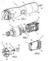
- FIG. 1 shows an appliance housing 1 comprising an elongated body whose longitudinal end is intended to be coupled to an accessory, such as a mixer accessory 100 or a mixing stand 200, shown in FIGS. 7 to 9.
- an accessory such as a mixer accessory 100 or a mixing stand 200, shown in FIGS. 7 to 9.
- the casing 1 comprises a body of circular section constituted by two shells 10 assembled one on the other and comprises a manual gripping zone having a maximum section near the longitudinal ends of the casing 1 and a restricted section in the central part of the casing 1.
- the end of the housing 1 intended to be coupled to the accessory has four threads 11 quarter turn regularly distributed over the periphery of the shells 10 which allow the coupling by screwing the accessory in four orientations offset 90 °.
- the locking in position of the accessory on the housing 1 is provided by a locking device 9 having teeth 90 resiliently projecting outside the body of the housing 1, these teeth 90 being intended to cooperate with ribs formed on the housing. 'accessory.
- the locking device 9 also comprises an unlocking button 91 which, when depressed, allows the teeth 90 to be erased inside the body of the casing 1.
- the rear end 1B of the casing for its part, has an opening for the passage of a power cord 12.
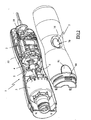
- the housing 1 encloses a motor 2 whose output shaft 20 is connected to the drive shaft 30 of a gearbox 3 having at its output a rotary gear train 31 with two speeds arranged opposite an opening 13 made in the partition closing the front end 1A of the housing.
- the motor 2 is disposed in the part of the housing 1 near the rear end 1B, the housing 1 having at this location a diameter slightly greater than the outside diameter of the engine 2 so that there is a slight gap between the engine 2 and the housing body 1 allowing the circulation of a flow of air.
- the motor 2 is arranged along the longitudinal axis of the housing 1 and is held by means of a damping element 4 on lugs 14 of the body of the housing 1, the motor 2 being preferably spaced from the gear 3 by more than 10 mm .
- the damping element 4, shown alone in FIG. 6, consists of two end elements 41 connected to each other by elastic links 42, the two end elements 41 being placed at the ends of the engine 2 and held thereon. by the elastic deformation of connections 41.
- the gearbox 3 is disposed in the part of the housing near the front end 1A, the housing 1 having at this location a diameter slightly greater than the outer diameter of the gearbox 3 so that there is a slight gap between the gearbox 3 and the body of the housing 1 allowing the circulation of a flow of air.
- the immobilization of the gearbox 3 is achieved by lugs 15 of the body of the casing 1 and the drive shaft 30 of the gearbox is preferably connected to the output shaft 20 of the motor by means of a universal joint 5 providing a flexible connection allowing misalignment between the drive shaft 30 of the gearbox and the output shaft 20 of the motor.
- This universal joint 5, shown disassembled in FIG. 5, is for example constituted by a ring 51, integral with the output shaft 20 of the engine, comprising grooves 52 in which are engaged flats 53 carried by the end of the drive shaft 30.
- the operation of the engine 2 is controlled by a switch 6 disposed next to the cardan shaft 5, in the free space existing between the motor 2 and the gearbox 3.
- the switch 6 is actuated by a control button 7 disposed at the level of the central portion of the housing 1 having a restricted section, the housing 1 having at this location an impression 16 adapted to the shape of a thumb whose bottom is formed by the actuating surface 70 of the control knob 7.
- the control button 7 acts on the switch 6 via an actuating member 71 extending laterally above the switch 6 and comprises slideways 72 cooperating with guide rails 17 carried by the one of the shells 10 of the housing 1 for guiding the control knob 7 in translation.
- the housing 1 is provided with a fan 8 integral with the drive shaft 30 of the gearbox 3 and disposed near the reducer 3, downstream of the control button 7.
- the fan 8 consists of a disk 80 provided with blades 81 on its two faces, the blades 81 adjacent to the reducer 3 driving the air around the latter in the direction the front end 1A of the housing, games being provided at the unlocking button 13 to allow the escape of the air flow generated by the fan 8.
- the blades 81 facing the engine 2 are in turn juxtaposed to a flange 18 carried by the shells 10 and cooperate with the flange 18 to suck the air on the side of the engine 2 through a central opening of the flange 18 , thus generating a depression in the central part of the body of the casing 1 and the admission of fresh air through games provided at the junction between a piece overmoulding of the cord 12 and the shells 10 of the casing 1.
- Such an arrangement of the fan 8 has the advantage of generating, inside the casing 1, a flow of air flowing from the overmoulding piece 19 of the cord 12 towards the unlocking button 90 which ensures the cooling of the motor 2 and reducer 3 without hot air delivery at the control knob 7.
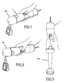
- FIGS. 7 and 8 illustrate the ergonomic advantages of use of the housing according to the invention according to the accessory used.
- the housing described above can be comfortably used in a horizontal position while being coupled to a drummer accessory 100.
- the user can adopt an ergonomic position by applying the inch to the height of the control button 7 and placing his hand straddling the central area and the rear part of the housing 1.
- the substantially balanced distribution of the masses around the control knob 7 obtained through the distribution of the engine and the reducer around the control button 7 contributes to the comfort of use.
- FIGS. 7 and 8 respectively illustrate, by way of examples, the use of the housing with the control button facing up and to the side.
- the control button can also be turned down if the user prefers to use the index finger or another finger, to operate the command button.
- Such a device also has the advantage of providing the same ergonomics of use for right-handed and left-handed users.
- the housing according to the invention may also be comfortably used in a vertical position, for example being coupled with a mixing stand 200.
- the housing according to the invention can be used with any type of accessory other than those previously described.
Abstract
Description
La présente invention concerne le domaine technique général des appareils électroménagers de préparation culinaire tenus à la main. La présente invention concerne plus particulièrement les appareils comportant un boîtier dont une extrémité peut être accouplée à différents types d'accessoires, tels qu'un pied de mixage ou un accessoire batteur, et pour lesquels le boîtier peut être tenu verticalement ou horizontalement en fonction de l'accessoire utilisé.The present invention relates to the general technical field of household appliances for culinary preparation held by hand. The present invention relates more particularly to devices comprising a housing whose one end can be coupled to different types of accessories, such as a mixing stand or a drumming attachment, and for which the housing can be held vertically or horizontally depending on the accessory used.
Il est connu, du document FR 1 303 638, un appareil électroménager comportant un boîtier cylindrique allongé intégrant un moteur dont l'arbre de sortie débouche à une extrémité longitudinale du boîtier pouvant indifféremment être accouplée à un pied de mixage ou à un accessoire batteur. Un tel appareil comporte un bouton de commande du moteur qui est disposé à proximité de l'extrémité du boîtier opposée à l'extrémité accouplée à l'accessoire, une telle disposition permettant une manipulation aisée du bouton avec le pouce lorsque le boîtier est utilisé verticalement avec le pied de mixage. Cependant, un tel emplacement du bouton de commande est inadapté à une utilisation horizontale du boîtier avec l'accessoire batteur, le bouton de commande se trouvant alors à l'opposé du pouce de la main tenant l'appareil.
Il est connu, du document US 4 856 718, un appareil électroménager de préparation culinaire comportant un boîtier cylindrique allongé intégrant un moteur et un réducteur dont une extrémité longitudinale peut être accouplée à différents accessoires. Un tel appareil comporte un bouton de commande du moteur placé sur une excroissance du boîtier disposé à hauteur du réducteur, à proximité de l'extrémité du boîtier accouplée à l'accessoire. Un tel emplacement permet une manipulation aisée du bouton de commande avec le pouce lorsque le boîtier est tenu horizontalement mais n'est pas adapté à une utilisation verticale du boîtier. De plus, l'emplacement du bouton de commande sur une excroissance du boîtier entraîne une position du pouce peu confortable favorisant la crispation.It is known from document US Pat. No. 4,856,718, an electrical appliance for culinary preparation comprising an elongate cylindrical housing incorporating a motor and a gearbox, a longitudinal end of which can be coupled to various accessories. Such an apparatus comprises a motor control button placed on a protrusion of the housing disposed at the height of the gearbox, near the end of the housing coupled to the accessory. Such a location allows easy manipulation of the control button with the thumb when the housing is held horizontally but is not suitable for vertical use of the housing. In addition, the location of the control button on a protrusion of the housing causes an uncomfortable thumb position favoring tension.
L'invention qui suit vise à pallier ces inconvénients en proposant un boîtier d'appareil électroménager procurant une grande ergonomie d'utilisation, en particulier dans la manipulation du bouton de commande du moteur, que le boîtier soit tenu verticalement ou horizontalement. L'invention vise également à proposer un boîtier d'appareil électroménager procurant un bon équilibre des masses par rapport à la zone de préhension lorsque le boîtier est tenu horizontalement.The following invention aims to overcome these disadvantages by providing a housing appliance providing great ergonomics of use, particularly in the handling of the engine control button, the housing is held vertically or horizontally. The invention also aims to provide an appliance housing providing a good balance of masses relative to the gripping area when the housing is held horizontally.
Le but de l'invention est atteint par un boîtier d'appareil électroménager de préparation culinaire selon la revendication 1.The object of the invention is achieved by a household appliance housing for culinary preparation according to
Une telle combinaison de caractéristiques permet, en conservant une longueur réduite du boîtier, de ménager longitudinalement une zone de préhension importante de part et d'autre du bouton de commande, facilitant la saisie lors d'une utilisation verticale ou horizontale du boîtier. De plus, une telle caractéristique permet également d'obtenir un bon équilibre des masses par rapport au bouton de commande lorsque le boîtier est utilisé horizontalement.Such a combination of features makes it possible, while maintaining a reduced length of the casing, to provide a longitudinal longitudinal zone of a large grip on either side of the control button, making it easier to grip during vertical or horizontal use of the casing. In addition, such a characteristic also makes it possible to obtain a good balance of masses with respect to the control button when the casing is used horizontally.
Selon une autre caractéristique de l'invention, le corps du boîtier présente une section transversale restreinte au niveau de l'emplacement du bouton de commande.According to another characteristic of the invention, the body of the housing has a restricted cross section at the location of the control button.
Une telle restriction de section au niveau de l'emplacement du bouton de commande présente l'avantage de procurer une grande ergonomie d'utilisation en permettant une position détendue de la mainSuch a section restriction at the location of the control button has the advantage of providing great ergonomics of use by allowing a relaxed position of the hand
Selon une autre caractéristique de l'invention, le moteur et le réducteur sont disposés aux deux extrémités longitudinales opposées du boîtier, le bouton de commande étant placé sensiblement dans la zone centrale du boîtier.According to another characteristic of the invention, the motor and the gearbox are arranged at the two opposite longitudinal ends of the housing, the control button being placed substantially in the central zone of the housing.
Une telle caractéristique permet d'optimiser l'emplacement des éléments dans le boîtier.Such a feature optimizes the location of the elements in the housing.
Selon une autre caractéristique de l'invention, le bouton de commande du moteur coopère avec un interrupteur placé entre le moteur et le réducteur.According to another characteristic of the invention, the motor control knob cooperates with a switch placed between the motor and the gearbox.
Une telle caractéristique permet d'avoir un boîtier de diamètre réduit au niveau du bouton de commande tout en utilisant un interrupteur conventionnel.Such a characteristic makes it possible to have a reduced diameter casing at the control button while using a conventional switch.
Selon une autre caractéristique de l'invention, le moteur comporte un arbre de sortie qui est relié à un arbre d'entraînement du réducteur au moyen d'un cardan assurant une liaison souple entre l'arbre de sortie du moteur et l'arbre d'entraînement du réducteur.According to another characteristic of the invention, the motor comprises an output shaft which is connected to a drive shaft of the gear unit by means of a universal joint ensuring a flexible connection between the output shaft of the motor and the drive shaft. gearbox drive.
Une telle caractéristique permet de s'affranchir de l'obligation d'avoir un parfait alignement entre l'arbre de sortie du moteur et l'arbre d'entraînement du réducteur.Such a feature eliminates the need to have a perfect alignment between the output shaft of the motor and the drive shaft of the reducer.
Selon une autre caractéristique de l'invention, les moyens d'accouplement avec l'accessoire comportent des filets quart de tour permettant de visser l'accessoire sur le corps du boîtier suivant quatre positions, décalées l'une de l'autre de 90°, et un système de verrouillage automatique comportant un bouton de déverrouillage pour libérer l'accessoire.According to another characteristic of the invention, the means for coupling with the accessory comprise quarter-turn threads enabling the accessory to be screwed onto the body of the box in four positions, offset from each other by 90 ° , and an automatic locking system comprising an unlocking button to release the accessory.
Une telle caractéristique permet de modifier l'orientation du bouton de commande par rapport à l'accessoire et donne ainsi la possibilité à l'utilisateur de choisir la position qui lui convient le mieux.Such a feature allows to change the orientation of the control button relative to the accessory and thus gives the opportunity to the user to choose the position that suits him best.
Selon encore une autre caractéristique de l'invention, le moteur et le réducteur sont refroidis par un ventilateur porté par l'arbre d'entraînement du réducteur et situé entre le réducteur et le bouton de commande, le ventilateur générant un flux d'air dans le corps du boîtier créant une dépression au niveau du bouton de commande.According to yet another characteristic of the invention, the motor and the gearbox are cooled by a fan carried by the drive shaft of the gearbox and located between the gearbox and the control button, the fan generating an air flow in the case body creating a depression at the control button.
Une telle caractéristique permet de refroidir le moteur et le réducteur par circulation d'un flux d'air dans le corps du boîtier sans que de l'air chaud, pouvant provoquer des brûlures, ne s'échappe au niveau du bouton de commande.Such a characteristic makes it possible to cool the motor and the reducer by circulating a flow of air in the body of the housing without hot air, which can cause burns, escaping at the control button.
Selon encore une autre caractéristique de l'invention, le ventilateur est constitué par un disque comportant des pales sur ses deux faces, le boîtier comportant un flasque de guidage du flux d'air à proximité des pales orientées vers le moteur.According to yet another characteristic of the invention, the fan is constituted by a disc having blades on both sides thereof, the housing comprising a flange for guiding the flow of air near the blades facing the motor.
Une telle caractéristique permet de contrôler l'orientation du flux d'air émis par le ventilateur de manière à optimiser son efficacité.Such a characteristic makes it possible to control the orientation of the air flow emitted by the fan so as to optimize its efficiency.
Selon une autre caractéristique de l'invention, le bouton de déverrouillage est disposé à proximité de l'extrémité du boîtier munie des moyens d'accouplement avec l'accessoire, le flux d'air engendré par le ventilateur s'échappant au travers d'un jeu prévu entre le bouton de déverrouillage et le corps du boîtier.According to another characteristic of the invention, the unlocking button is disposed near the end of the housing provided with means for coupling with the accessory, the air flow generated by the fan escaping through the a game provided between the unlocking button and the body of the housing.
Une telle caractéristique présente l'avantage d'assurer simplement, et à moindre coût, l'évacuation du flux d'air chaud sans risque de brûlure de l'utilisateur, le bouton de déverrouillage n'étant manipulé que lorsque l'appareil est arrêté.Such a characteristic has the advantage of ensuring simply and at a lower cost, the evacuation of the hot air flow without risk of burning the user, the unlocking button being manipulated only when the device is stopped .
Selon encore une autre caractéristique de l'invention, le moteur est alimenté par un cordon d'alimentation passant au travers d'une ouverture ménagée dans l'extrémité longitudinale du boîtier opposée à l'extrémité comportant les moyens d'accouplement avec l'accessoire et il est prévu un jeu à la jonction entre le cordon d'alimentation et le corps du boîtier permettant l'admission d'air dans le corps du boîtier lors du fonctionnement du ventilateur.According to yet another characteristic of the invention, the motor is powered by a power cord passing through an opening in the longitudinal end of the housing opposite the end comprising the coupling means with the accessory. and there is a clearance at the junction between the power cord and the body of the housing allowing the admission of air into the housing body during operation of the fan.
Une telle caractéristique présente l'avantage de créer, à moindre coût, une arrivée d'air frais alimentant le flux d'air circulant dans le corps du boîtier.Such a feature has the advantage of creating, at lower cost, a fresh air supply supplying the flow of air flowing in the body of the housing.
Selon encore une autre caractéristique de l'invention, un élément amortisseur est interposé entre le moteur et le corps du boîtier, cet élément amortisseur comportant des éléments d'extrémité disposés à chacune des extrémités longitudinales du moteur qui sont reliés entre eux par des bras de liaison élastiques.According to yet another characteristic of the invention, a damping element is interposed between the motor and the body of the casing, this damping element comprising end elements disposed at each of the longitudinal ends of the motor which are interconnected by arms of elastic connection.
Une telle caractéristique permet d'obtenir un élément amortisseur atténuant les vibrations qui reste solidaire du moteur une fois monté sur ce dernier, ce qui présente l'avantage de simplifier l'opération de montage.Such a characteristic makes it possible to obtain a vibration damping damping element which remains integral with the motor once mounted on the latter, which has the advantage of simplifying the mounting operation.
L'invention concerne également un appareil électroménager de préparation culinaire comportant un boîtier selon l'invention associé à un accessoire, tel un pied de mixage ou un accessoire batteur.The invention also relates to an electrical household appliance for culinary preparation comprising a housing according to the invention associated with an accessory, such as a mixing stand or a drummer attachment.
On comprendra mieux les buts, aspects et avantages de la présente invention, d'après la description donnée ci-après d'un mode particulier de réalisation de l'invention présenté à titre d'exemple non limitatif, en se référant aux dessins annexés dans lesquels :
- la figure 1 est une vue en perspective d'un boîtier d'appareil électroménager selon un mode particulier de réalisation de l'invention ;
- la figure 2 est une vue en perspective partiellement éclatée du boîtier de la figure 1 ;
- la figure 3 est une autre vue en perspective du boîtier de la figure 1 avec sa coquille supérieure démontée;
- la figure 4 représente une vue en perspective des moteur et réducteur intégrés dans le boîtier de la figure 1 ;
- la figure 5 est une vue de détail, en perspective, du cardan assurant la liaison souple entre l'arbre d'entraînement du réducteur et l'arbre de sortie du moteur.
- la figure 6 est une vue de détail de l'élément amortisseur supportant le moteur ;
- les figures 7 à 9 illustrent des exemples de positions ergonomiques d'utilisation du boîtier de l'appareil en adéquation avec l'accessoire utilisé.
- Figure 1 is a perspective view of a household appliance housing according to a particular embodiment of the invention;
- Figure 2 is a partially exploded perspective view of the housing of Figure 1;
- Figure 3 is another perspective view of the housing of Figure 1 with its upper shell disassembled;
- FIG. 4 represents a perspective view of the motor and gearbox integrated in the housing of FIG. 1;
- Figure 5 is a detailed view, in perspective, of the gimbal ensuring the flexible connection between the drive shaft of the gearbox and the output shaft of the motor.
- Figure 6 is a detailed view of the damping element supporting the engine;
- Figures 7 to 9 illustrate examples of ergonomic positions of use of the housing of the device in line with the accessory used.
Seuls les éléments nécessaires à la compréhension de l'invention ont été représentés. Pour faciliter la lecture des dessins, les mêmes éléments portent les mêmes références d'une figure à l'autre.Only the elements necessary for the understanding of the invention have been represented. To facilitate the reading of the drawings, the same elements bear the same references from one figure to another.
La figure 1 représente un boîtier 1 d'appareil électroménager comportant un corps de forme allongée dont une extrémité longitudinale est destinée à être accouplée à un accessoire, tel un accessoire batteur 100 ou un pied de mixage 200, représentés sur les figures 7 à 9.FIG. 1 shows an
Conformément à la figure 1, le boîtier 1 comporte un corps de section circulaire constitué par deux coquilles 10 assemblées l'une sur l'autre et comprend une zone de préhension manuelle comportant une section maximale à proximité des extrémités longitudinales du boîtier 1 et une section restreinte dans la partie centrale du boîtier 1.According to FIG. 1, the
L'extrémité du boîtier 1 destinée à être accouplée à l'accessoire, dite extrémité antérieure 1A, possède quatre filets 11 quart de tour régulièrement répartis sur la périphérie des coquilles 10 qui permettent l'accouplement par vissage de l'accessoire suivant quatre orientations décalées de 90°. Le verrouillage en position de l'accessoire sur le boîtier 1 est assuré par un dispositif de verrouillage 9 comportant des dentures 90 faisant élastiquement saillie à l'extérieur du corps du boîtier 1, ces dentures 90 étant destinées à coopérer avec des nervures formées sur l'accessoire. Le dispositif de verrouillage 9 comporte également un bouton de déverrouillage 91 qui, lorsqu'il est enfoncé, permet d'effacer les dentures 90 à l'intérieur du corps du boîtier 1. L'extrémité postérieure 1B du boîtier comporte quant à elle une ouverture pour le passage d'un cordon d'alimentation électrique 12.The end of the
Conformément aux figures 2 et 3, le boîtier 1 renferme un moteur 2 dont l'arbre de sortie 20 est relié à l'arbre d'entraînement 30 d'un réducteur 3 comportant en sortie un entraîneur rotatif 31 à deux vitesses agencé en regard d'une ouverture 13 pratiquée dans la cloison fermant l'extrémité antérieur 1A du boîtier.According to FIGS. 2 and 3, the
Le moteur 2 est disposé dans la partie du boîtier 1 proche de l'extrémité postérieure 1B, le boîtier 1 présentant à cet endroit un diamètre légèrement supérieur au diamètre extérieur du moteur 2 de sorte qu'il résulte un léger espace entre le moteur 2 et le corps du boîtier 1 permettant la circulation d'un flux d'air. Le moteur 2 est agencé selon l'axe longitudinal du boîtier 1 et est maintenu par l'intermédiaire d'un élément amortisseur 4 sur des pattes 14 du corps du boîtier 1, le moteur 2 étant préférentiellement espacé du réducteur 3 de plus de 10 mm. L'élément amortisseur 4, représenté seul sur la figure 6, est constitué par deux éléments d'extrémité 41 reliés entre eux par des liaisons élastiques 42, les deux éléments d'extrémité 41 étant placés aux extrémités du moteur 2 et maintenus sur ces dernières par la déformation élastique des liaisons 41.The
Le réducteur 3 est disposé dans la partie du boîtier proche de l'extrémité antérieure 1A, le boîtier 1 présentant à cet endroit un diamètre légèrement supérieur au diamètre extérieur du réducteur 3 de sorte qu'il résulte un léger espace entre le réducteur 3 et le corps du boîtier 1 permettant la circulation d'un flux d'air.The
L'immobilisation du réducteur 3 est réalisée par des pattes 15 du corps du boîtier 1 et l'arbre d'entraînement 30 du réducteur est préférentiellement relié à l'arbre de sortie 20 du moteur au moyen d'un cardan 5 assurant une liaison souple autorisant un mauvais alignement entre l'arbre d'entraînement 30 du réducteur et l'arbre de sortie 20 du moteur.The immobilization of the
Ce cardan 5, représenté démonté sur la figure 5, est par exemple constitué d'une bague 51, solidaire de l'arbre de sortie 20 du moteur, comprenant des rainures 52 dans lesquelles viennent s'engager des méplats 53 portés par l'extrémité de l'arbre d'entraînement 30.This
Le fonctionnement du moteur 2 est contrôlé par un interrupteur 6 disposé à côté du cardan 5, dans l'espace libre existant entre le moteur 2 et le réducteur 3. L'interrupteur 6 est actionné par un bouton de commande 7 disposé au niveau de la partie centrale du boîtier 1 présentant une section restreinte, le boîtier 1 comportant à cet endroit une empreinte 16 adaptée à la forme d'un pouce dont le fond est formé par la surface d'actionnement 70 du bouton de commande 7.The operation of the
Le bouton de commande 7 agit sur l'interrupteur 6 par l'intermédiaire d'un organe d'actionnement 71 s'étendant latéralement au-dessus de l'interrupteur 6 et comporte des glissières 72 coopérant avec des rails de guidage 17 portés par l'une des coquilles 10 du boîtier 1 pour assurer le guidage en translation du bouton de commande 7.The
Afin d'éviter l'échauffement excessif du moteur 2 et du réducteur 3 lors du fonctionnement de l'appareil, le boîtier 1 est muni d'un ventilateur 8 solidaire de l'arbre d'entraînement 30 du réducteur 3 et disposé à proximité du réducteur 3, en aval du bouton de commande 7.In order to prevent excessive heating of the
Comme on peut le voir plus précisément sur les figures 3 et 5, le ventilateur 8 est constitué d'un disque 80 muni de pales 81 sur ses deux faces, les pales 81 adjacentes au réducteur 3 chassant l'air autour de ce dernier en direction de l'extrémité antérieure 1A du boîtier, des jeux étant prévus au niveau du bouton de déverrouillage 13 pour permettre l'échappement du flux d'air généré par le ventilateur 8.As can be seen more specifically in FIGS. 3 and 5, the
Les pales 81 orientées vers le moteur 2 sont quant à elles juxtaposées à un flasque 18 porté par les coquilles 10 et coopèrent avec ce flasque 18 pour aspirer l'air se trouvant du côté du moteur 2 au travers d'une ouverture centrale du flasque 18, générant ainsi une dépression dans la partie centrale du corps du boîtier 1 et l'admission d'air frais au travers de jeux prévus à la jonction entre une pièce 19 de surmoulage du cordon 12 et les coquilles 10 du boîtier 1.The
Une telle disposition du ventilateur 8 présente l'avantage de générer, à l'intérieur du boîtier 1, un flux d'air circulant de la pièce 19 de surmoulage du cordon 12 vers le bouton de déverrouillage 90 qui assure le refroidissement du moteur 2 et du réducteur 3 sans refoulement d'air chaud au niveau du bouton de commande 7.Such an arrangement of the
Les figures 7 à 9 illustrent les avantages ergonomiques d'utilisation du boîtier selon l'invention en fonction de l'accessoire utilisé. Ainsi, conformément aux figures 7 et 8, le boîtier précédemment décrit pourra être utilisé confortablement dans une position horizontale en étant accouplé à un accessoire batteur 100. En effet, lors d'une telle utilisation l'utilisateur pourra adopter une position ergonomique en appliquant le pouce à hauteur du bouton de commande 7 et en plaçant sa main à cheval sur la zone centrale et la partie postérieure du boîtier 1. Dans cette position, la répartition sensiblement équilibrée des masses autour du bouton de commande 7 obtenue grâce à la répartition du moteur et du réducteur autour du bouton de commande 7 participe au confort d'utilisation.Figures 7 to 9 illustrate the ergonomic advantages of use of the housing according to the invention according to the accessory used. Thus, in accordance with FIGS. 7 and 8, the housing described above can be comfortably used in a horizontal position while being coupled to a
De plus, l'accessoire batteur 100 peut être vissé sur le boîtier suivant quatre positions différentes, décalées de 90°, ce qui permet à l'utilisateur d'orienter le bouton de commande en fonction de sa convenance. Ainsi, les figures 7 et 8 illustrent respectivement, à titre d'exemples, l'utilisation du boîtier avec le bouton de commande orienté vers le haut et sur le côté. Dans une variante d'utilisation non représentée, le bouton de commande pourra également être orienté vers le bas si l'utilisateur préfère utiliser l'index ou un autre doigt, pour actionner le bouton de commande.In addition, the
Un tel appareil présente également l'avantage de procurer la même ergonomie d'utilisation pour les droitiers et les gauchers.Such a device also has the advantage of providing the same ergonomics of use for right-handed and left-handed users.
Conformément à la figure 9, le boîtier selon l'invention pourra aussi être confortablement utilisé dans une position verticale, en étant par exemple accouplé avec un pied de mixage 200.According to Figure 9, the housing according to the invention may also be comfortably used in a vertical position, for example being coupled with a mixing
Bien entendu, l'invention n'est nullement limitée au mode de réalisation décrit et illustré qui n'a été donné qu'à titre d'exemple. Des modifications restent possibles, notamment du point de vue de la constitution des divers éléments ou par substitution d'équivalents techniques, sans sortir pour autant du domaine de protection de l'invention.Of course, the invention is not limited to the embodiment described and illustrated which has been given by way of example. Modifications are possible, particularly from the point of view of the constitution of the various elements or by substitution of technical equivalents, without departing from the scope of protection of the invention.
Ainsi, le boîtier selon l'invention pourra être utilisé avec tout type d'accessoire autre que ceux précédemment décrits.Thus, the housing according to the invention can be used with any type of accessory other than those previously described.
Claims (12)
- A household electrical appliance housing (1) for a household electrical appliance for preparing food, which housing contains a motor (2) coupled to a gearbox (3) provided with a rotary driver (31) arranged to face an opening (13) provided in a longitudinal end (1A) of the housing (1), said longitudinal end (1A) being provided with coupling means for coupling to a beater accessory (100) or to a blender attachment (200), the housing being designed to be held horizontally or vertically as a function of the accessory being used, and having a body including a graspable zone of elongate shape for being held in the hand, said body enclosing the motor (2) and the gearbox (3), operation of the motor (2) being controlled by a control button (7) carried by the housing (1), said household electrical appliance housing being characterized in that the motor (2) and the gearbox (3) are spaced apart from each other, and in that the control button (7) is placed longitudinally on that zone of the housing (1) which is disposed between the motor (2) and the gearbox (3) so as to form longitudinally, on either side of the control button (7) a graspable zone via which the housing (1) can be taken hold of on the body enclosing the motor (2) and the gearbox (3).
- A household electrical appliance housing according to claim 1, characterized in that the body of the housing (1) has a cross-section that is smaller at the location of the control button (7).
- A household electrical appliance housing according to claim 1 or claim 2, characterized in that the motor (2) and the gearbox (3) are disposed at opposite longitudinal ends (1A, 1B) of the housing (1), the control button (7) being placed substantially in the central zone of the housing (1).
- A household electrical appliance housing according to claim 2 or claim 3, characterized in that the control button (7) of the motor (2) co-operates with a switch (6) placed between the motor (2) and the gearbox (3).
- A household electrical appliance housing according to any one of claims 2 to 4, characterized in that the motor (2) has an outlet shaft (20) that is connected to a drive shaft (30) of the gearbox (3) by means of a universal joint (5) providing a flexible link between the outlet shaft (20) and the drive shaft (30).
- A household electrical appliance according to any one of claims 1 to 5, characterized in that the means for coupling to the accessory (100; 200) comprise quarter-turn thread starts (11) making it possible to screw the accessory to the body of the housing (1) in respective ones of four positions that are offset from one another by 90°, and an automatic locking system (9) having an unlocking button (91) for releasing the accessory (100; 200).
- A household electrical appliance housing according to any one of claims 2 to 6, characterized in that the motor (2) and the gearbox (3) are cooled by a fan (8) carried by the drive shaft (30) of the gearbox (3) and situated between the gearbox (3) and the control button (7), said fan (8) generating a flow of air through the body of the housing (1), thereby generating suction at the control button (7).
- A household electrical appliance housing according to claim 7, characterized in that the fan (8) is constituted by a disk (80) provided with paddles (81) on both of its faces, and in that the housing (1) has a flange (18) for guiding the flow air in the vicinity of those paddles (81) which extend towards the motor (2).
- A household electrical appliance housing according to claims 6 and 8, characterized in that the unlocking button (91) is disposed in the vicinity of the end (1A) of the housing that is provided with the coupling means, the flow of air generated by the fan escaping through clearance provided between the unlocking button (91) and the body of the housing (1).
- A household electrical appliance housing according to any one of claims 7 to 9, characterized in that the motor (2) is powered via a power supply cord (12) passing through an opening (12) provided in that longitudinal end (1B) of the housing that is opposite from the end (1A) that is provided with the coupling means for coupling to the accessory and in that clearance is provided where the body of the housing (1) meets the power supply cord (12), which clearance enables air to be taken into the body of the housing (1) while the fan (8) is operating.
- A household electrical appliance housing according to any one of claims 1 to 10, characterized in that a vibration damper element (4) is interposed between the motor (2) and the body of the housing (1), said vibration damper element (4) comprises end elements (41) disposed at respective ones of the longitudinal ends of the motor (2) and interconnected by resilient link means (42).
- A household electrical appliance for preparing food, said appliance including a housing (1) associated with an accessory such as a blender attachment (200) or a beater accessory (100), said household electrical appliance being characterized in that it includes a housing (1) according to any one of claims 1 to 11.
Applications Claiming Priority (2)
| Application Number | Priority Date | Filing Date | Title |
|---|---|---|---|
| FR0312918 | 2003-11-04 | ||
| FR0312918A FR2861568B1 (en) | 2003-11-04 | 2003-11-04 | CULINARY PREPARATION HOUSEHOLD APPLIANCE HOUSING PROVIDED FOR HAND HELD ACCORDING TO DIFFERENT POSITIONS |
Publications (2)
| Publication Number | Publication Date |
|---|---|
| EP1529473A1 EP1529473A1 (en) | 2005-05-11 |
| EP1529473B1 true EP1529473B1 (en) | 2007-05-23 |
Family
ID=34429875
Family Applications (1)
| Application Number | Title | Priority Date | Filing Date |
|---|---|---|---|
| EP04356162A Not-in-force EP1529473B1 (en) | 2003-11-04 | 2004-10-08 | Housing for electrical household cooking appliance designed to be hand-held in different positions |
Country Status (6)
| Country | Link |
|---|---|
| EP (1) | EP1529473B1 (en) |
| CN (1) | CN100531637C (en) |
| AT (1) | ATE362724T1 (en) |
| DE (1) | DE602004006581D1 (en) |
| ES (1) | ES2286576T3 (en) |
| FR (1) | FR2861568B1 (en) |
Families Citing this family (7)
| Publication number | Priority date | Publication date | Assignee | Title |
|---|---|---|---|---|
| WO2007007448A1 (en) * | 2005-07-07 | 2007-01-18 | Matsushita Electric Industrial Co., Ltd. | Food processor |
| FR2910260B1 (en) * | 2006-12-22 | 2009-01-23 | Seb Sa | STORAGE BOX FOR MIXING HOUSEHOLD TYPE OF DIVE. |
| EP2198761A1 (en) | 2008-12-18 | 2010-06-23 | Koninklijke Philips Electronics N.V. | Release system for kitchen utensil |
| FR2954079B1 (en) * | 2009-12-18 | 2012-07-27 | Seb Sa | CULINARY PREPARING ELECTRICAL APPLIANCE APPARATUS PROVIDED FOR HAND-HELDING WITH A PARTICULAR CONTROL DEVICE |
| FR2977784B1 (en) | 2011-07-13 | 2013-07-12 | Seb Sa | PRESS-PUREE DEVICE GRID AND CULINARY PREPARATION ELECTRICAL APPLIANCE COMPRISING SUCH A GRID |
| FR2977785B1 (en) | 2011-07-13 | 2013-07-05 | Seb Sa | CULINARY PREPARATION ELECTRICAL APPLIANCE COMPRISING A PRESS-PUREE DEVICE |
| KR101448464B1 (en) * | 2013-11-29 | 2014-10-13 | 김순련 | Separable handmixer |
Family Cites Families (8)
| Publication number | Priority date | Publication date | Assignee | Title |
|---|---|---|---|---|
| US2048455A (en) * | 1934-12-12 | 1936-07-21 | Dominion Electrical Mfg Co | Food mixing device with beater ejector |
| US2707623A (en) * | 1952-11-12 | 1955-05-03 | Dormeyer Corp | Portable food mixer |
| FR1303638A (en) | 1961-08-04 | 1962-09-14 | Expl Chimie Et Mecanique E C E | Beater-reduction unit adaptable to mixer |
| FR2537424B1 (en) * | 1982-12-09 | 1987-07-24 | Moulinex Sa | HOUSEHOLD APPLIANCE, SUCH AS A MIXER, EQUIPPED WITH A REMOVABLE BATTERY ACCESSORY |
| US4856718A (en) | 1987-12-04 | 1989-08-15 | Better Mousetraps Inc. | Food processor and food cutting devices therefor |
| DE19635223A1 (en) * | 1996-08-30 | 1998-03-05 | Bosch Siemens Hausgeraete | Rod mixer with grip part |
| ES2190714B1 (en) * | 2000-12-05 | 2004-04-01 | Cristobal Lozano Fernandez | CONTROLLED FLOW CLEANING NOZZLE. |
| CN2520806Y (en) * | 2001-09-19 | 2002-11-20 | 东莞市联创电器有限公司 | Multifunction food stirring machine |
-
2003
- 2003-11-04 FR FR0312918A patent/FR2861568B1/en not_active Expired - Fee Related
-
2004
- 2004-10-08 ES ES04356162T patent/ES2286576T3/en active Active
- 2004-10-08 AT AT04356162T patent/ATE362724T1/en not_active IP Right Cessation
- 2004-10-08 EP EP04356162A patent/EP1529473B1/en not_active Not-in-force
- 2004-10-08 DE DE602004006581T patent/DE602004006581D1/en active Active
- 2004-11-03 CN CNB2004100883627A patent/CN100531637C/en not_active Expired - Fee Related
Non-Patent Citations (1)
| Title |
|---|
| None * |
Also Published As
| Publication number | Publication date |
|---|---|
| DE602004006581D1 (en) | 2007-07-05 |
| CN100531637C (en) | 2009-08-26 |
| ES2286576T3 (en) | 2007-12-01 |
| CN1613415A (en) | 2005-05-11 |
| ATE362724T1 (en) | 2007-06-15 |
| FR2861568B1 (en) | 2005-12-30 |
| EP1529473A1 (en) | 2005-05-11 |
| FR2861568A1 (en) | 2005-05-06 |
Similar Documents
| Publication | Publication Date | Title |
|---|---|---|
| EP1772087B1 (en) | Mixing rod and domestic mixing device of the immersing type with such a mixing rod | |
| FR2508952A1 (en) | PORTABLE SCANNING APPARATUS | |
| WO2012136906A2 (en) | Standalone portable electric blower with variable air exit speed | |
| FR2794195A1 (en) | FAN EQUIPPED WITH AIR HANDLE | |
| FR2669850A1 (en) | Scrub-clearing machine equipped with a driven shaft mounted in a protective tube between the cutting head and the operating motor | |
| EP1529473B1 (en) | Housing for electrical household cooking appliance designed to be hand-held in different positions | |
| FR2905584A1 (en) | Household plender i.e. culinary preparation household hand-held plender, for beating egg white, has protecting cover, whose peripheral wall covers half of periphery of working tool to define mixing volume closed around working tool | |
| FR2920406A3 (en) | Drive arrangement comprises a housing containing a drive unit with a vertical drive shaft part, a horizontal drive shaft part, a longitudinal drive shaft part, a flywheel and drive crank elements | |
| FR2801169A1 (en) | PORTABLE TRIMMER WITH INTERNAL COMBUSTION ENGINE | |
| EP3079544B1 (en) | Household food preparation appliance comprising a lower arm borne by a base and an upper arm connected to the lower arm by a hinge means | |
| EP3079545B1 (en) | Household food preparation appliance comprising a base, a lower arm and an upper arm pivotably mounted on the lower arm | |
| EP1935302B1 (en) | Storage case for immersed domestic mixer | |
| EP1529472A1 (en) | Electric household appliance for food processing comprising an accessory removably coupled to a housing | |
| EP3079542B1 (en) | Household food preparation appliance comprising a lower arm borne by a base and an upper arm connected to the lower arm by a hinge means | |
| EP1604598B1 (en) | Housing for household cooking appliance designed to be hand-held | |
| FR3083688A1 (en) | VENTILATION SYSTEM FOR A PORTABLE HOUSEHOLD APPLIANCE FOR PROCESSING FOOD PREPARATIONS, MIXER / BATTER TYPE | |
| FR2775921A1 (en) | MANUALLY GUIDED WORKING INSTRUMENT COMPRISING A TRANSMISSION SHAFT ROTATING IN A SMOOTH BEARING OF A PROTECTIVE TUBE | |
| EP3079543B1 (en) | Household food preparation appliance comprising a base, a lower arm and an upper arm connected to one another by hinge means | |
| FR2945432A1 (en) | CULINARY PREPARATION ELECTRICAL APPLIANCE COMPRISING A WORKING CONTAINER IN THERMAL CONTACT WITH A HEATING ELEMENT | |
| FR2861567A1 (en) | Electric kitchen utensil has motor vibration dampers linked by lengthwise elastic connecting arms to form a single interface assembly | |
| FR3130524A1 (en) | STYLING DEVICE INCLUDING AN IMPROVED BLOWER MODULE WITH CONTRAROTIVE PROPELLERS | |
| FR2929094A1 (en) | Working head for use in hand-held household culinary preparation apparatus for e.g. cutting carrot, has body including handle with gripping zone extended at proximity of supply spout, and pusher including end with tab extended above handle | |
| FR3109138A1 (en) | Double paddle rotating handles | |
| FR3127382A1 (en) | WHISK FOR FOOD PREPARATION APPLIANCE | |
| FR3109515A1 (en) | Suction head cleaning unit |
Legal Events
| Date | Code | Title | Description |
|---|---|---|---|
| PUAI | Public reference made under article 153(3) epc to a published international application that has entered the european phase |
Free format text: ORIGINAL CODE: 0009012 |
|
| AK | Designated contracting states |
Kind code of ref document: A1 Designated state(s): AT BE BG CH CY CZ DE DK EE ES FI FR GB GR HU IE IT LI LU MC NL PL PT RO SE SI SK TR |
|
| AX | Request for extension of the european patent |
Extension state: AL HR LT LV MK |
|
| 17P | Request for examination filed |
Effective date: 20051108 |
|
| AKX | Designation fees paid |
Designated state(s): AT BE BG CH CY CZ DE DK EE ES FI FR GB GR HU IE IT LI LU MC NL PL PT RO SE SI SK TR |
|
| 17Q | First examination report despatched |
Effective date: 20060406 |
|
| GRAP | Despatch of communication of intention to grant a patent |
Free format text: ORIGINAL CODE: EPIDOSNIGR1 |
|
| GRAS | Grant fee paid |
Free format text: ORIGINAL CODE: EPIDOSNIGR3 |
|
| GRAA | (expected) grant |
Free format text: ORIGINAL CODE: 0009210 |
|
| AK | Designated contracting states |
Kind code of ref document: B1 Designated state(s): AT BE BG CH CY CZ DE DK EE ES FI FR GB GR HU IE IT LI LU MC NL PL PT RO SE SI SK TR |
|
| PG25 | Lapsed in a contracting state [announced via postgrant information from national office to epo] |
Ref country code: FI Free format text: LAPSE BECAUSE OF FAILURE TO SUBMIT A TRANSLATION OF THE DESCRIPTION OR TO PAY THE FEE WITHIN THE PRESCRIBED TIME-LIMIT Effective date: 20070523 |
|
| REG | Reference to a national code |
Ref country code: GB Ref legal event code: FG4D Free format text: NOT ENGLISH |
|
| REG | Reference to a national code |
Ref country code: CH Ref legal event code: EP |
|
| REG | Reference to a national code |
Ref country code: IE Ref legal event code: FG4D Free format text: LANGUAGE OF EP DOCUMENT: FRENCH |
|
| REF | Corresponds to: |
Ref document number: 602004006581 Country of ref document: DE Date of ref document: 20070705 Kind code of ref document: P |
|
| GBT | Gb: translation of ep patent filed (gb section 77(6)(a)/1977) |
Effective date: 20070628 |
|
| PG25 | Lapsed in a contracting state [announced via postgrant information from national office to epo] |
Ref country code: SE Free format text: LAPSE BECAUSE OF FAILURE TO SUBMIT A TRANSLATION OF THE DESCRIPTION OR TO PAY THE FEE WITHIN THE PRESCRIBED TIME-LIMIT Effective date: 20070823 |
|
| NLV1 | Nl: lapsed or annulled due to failure to fulfill the requirements of art. 29p and 29m of the patents act | ||
| PG25 | Lapsed in a contracting state [announced via postgrant information from national office to epo] |
Ref country code: AT Free format text: LAPSE BECAUSE OF FAILURE TO SUBMIT A TRANSLATION OF THE DESCRIPTION OR TO PAY THE FEE WITHIN THE PRESCRIBED TIME-LIMIT Effective date: 20070523 Ref country code: PL Free format text: LAPSE BECAUSE OF FAILURE TO SUBMIT A TRANSLATION OF THE DESCRIPTION OR TO PAY THE FEE WITHIN THE PRESCRIBED TIME-LIMIT Effective date: 20070523 |
|
| REG | Reference to a national code |
Ref country code: ES Ref legal event code: FG2A Ref document number: 2286576 Country of ref document: ES Kind code of ref document: T3 |
|
| REG | Reference to a national code |
Ref country code: IE Ref legal event code: FD4D |
|
| PG25 | Lapsed in a contracting state [announced via postgrant information from national office to epo] |
Ref country code: BG Free format text: LAPSE BECAUSE OF FAILURE TO SUBMIT A TRANSLATION OF THE DESCRIPTION OR TO PAY THE FEE WITHIN THE PRESCRIBED TIME-LIMIT Effective date: 20070823 Ref country code: CZ Free format text: LAPSE BECAUSE OF FAILURE TO SUBMIT A TRANSLATION OF THE DESCRIPTION OR TO PAY THE FEE WITHIN THE PRESCRIBED TIME-LIMIT Effective date: 20070523 Ref country code: NL Free format text: LAPSE BECAUSE OF FAILURE TO SUBMIT A TRANSLATION OF THE DESCRIPTION OR TO PAY THE FEE WITHIN THE PRESCRIBED TIME-LIMIT Effective date: 20070523 Ref country code: PT Free format text: LAPSE BECAUSE OF FAILURE TO SUBMIT A TRANSLATION OF THE DESCRIPTION OR TO PAY THE FEE WITHIN THE PRESCRIBED TIME-LIMIT Effective date: 20071023 Ref country code: DK Free format text: LAPSE BECAUSE OF FAILURE TO SUBMIT A TRANSLATION OF THE DESCRIPTION OR TO PAY THE FEE WITHIN THE PRESCRIBED TIME-LIMIT Effective date: 20070523 Ref country code: IE Free format text: LAPSE BECAUSE OF FAILURE TO SUBMIT A TRANSLATION OF THE DESCRIPTION OR TO PAY THE FEE WITHIN THE PRESCRIBED TIME-LIMIT Effective date: 20070523 Ref country code: SI Free format text: LAPSE BECAUSE OF FAILURE TO SUBMIT A TRANSLATION OF THE DESCRIPTION OR TO PAY THE FEE WITHIN THE PRESCRIBED TIME-LIMIT Effective date: 20070523 |
|
| PG25 | Lapsed in a contracting state [announced via postgrant information from national office to epo] |
Ref country code: SK Free format text: LAPSE BECAUSE OF FAILURE TO SUBMIT A TRANSLATION OF THE DESCRIPTION OR TO PAY THE FEE WITHIN THE PRESCRIBED TIME-LIMIT Effective date: 20070523 |
|
| PLBE | No opposition filed within time limit |
Free format text: ORIGINAL CODE: 0009261 |
|
| STAA | Information on the status of an ep patent application or granted ep patent |
Free format text: STATUS: NO OPPOSITION FILED WITHIN TIME LIMIT |
|
| 26N | No opposition filed |
Effective date: 20080226 |
|
| BERE | Be: lapsed |
Owner name: SEB S.A. Effective date: 20071031 |
|
| PG25 | Lapsed in a contracting state [announced via postgrant information from national office to epo] |
Ref country code: DE Free format text: LAPSE BECAUSE OF FAILURE TO SUBMIT A TRANSLATION OF THE DESCRIPTION OR TO PAY THE FEE WITHIN THE PRESCRIBED TIME-LIMIT Effective date: 20070824 Ref country code: GR Free format text: LAPSE BECAUSE OF FAILURE TO SUBMIT A TRANSLATION OF THE DESCRIPTION OR TO PAY THE FEE WITHIN THE PRESCRIBED TIME-LIMIT Effective date: 20070824 |
|
| PG25 | Lapsed in a contracting state [announced via postgrant information from national office to epo] |
Ref country code: MC Free format text: LAPSE BECAUSE OF NON-PAYMENT OF DUE FEES Effective date: 20071031 Ref country code: RO Free format text: LAPSE BECAUSE OF FAILURE TO SUBMIT A TRANSLATION OF THE DESCRIPTION OR TO PAY THE FEE WITHIN THE PRESCRIBED TIME-LIMIT Effective date: 20070523 |
|
| PG25 | Lapsed in a contracting state [announced via postgrant information from national office to epo] |
Ref country code: BE Free format text: LAPSE BECAUSE OF NON-PAYMENT OF DUE FEES Effective date: 20071031 |
|
| REG | Reference to a national code |
Ref country code: FR Ref legal event code: ST Effective date: 20080630 |
|
| PG25 | Lapsed in a contracting state [announced via postgrant information from national office to epo] |
Ref country code: EE Free format text: LAPSE BECAUSE OF FAILURE TO SUBMIT A TRANSLATION OF THE DESCRIPTION OR TO PAY THE FEE WITHIN THE PRESCRIBED TIME-LIMIT Effective date: 20070523 |
|
| PG25 | Lapsed in a contracting state [announced via postgrant information from national office to epo] |
Ref country code: FR Free format text: LAPSE BECAUSE OF NON-PAYMENT OF DUE FEES Effective date: 20071031 |
|
| REG | Reference to a national code |
Ref country code: CH Ref legal event code: PL |
|
| PG25 | Lapsed in a contracting state [announced via postgrant information from national office to epo] |
Ref country code: CY Free format text: LAPSE BECAUSE OF FAILURE TO SUBMIT A TRANSLATION OF THE DESCRIPTION OR TO PAY THE FEE WITHIN THE PRESCRIBED TIME-LIMIT Effective date: 20070523 |
|
| PG25 | Lapsed in a contracting state [announced via postgrant information from national office to epo] |
Ref country code: LU Free format text: LAPSE BECAUSE OF NON-PAYMENT OF DUE FEES Effective date: 20071008 |
|
| PG25 | Lapsed in a contracting state [announced via postgrant information from national office to epo] |
Ref country code: TR Free format text: LAPSE BECAUSE OF FAILURE TO SUBMIT A TRANSLATION OF THE DESCRIPTION OR TO PAY THE FEE WITHIN THE PRESCRIBED TIME-LIMIT Effective date: 20070523 Ref country code: HU Free format text: LAPSE BECAUSE OF FAILURE TO SUBMIT A TRANSLATION OF THE DESCRIPTION OR TO PAY THE FEE WITHIN THE PRESCRIBED TIME-LIMIT Effective date: 20071124 |
|
| PG25 | Lapsed in a contracting state [announced via postgrant information from national office to epo] |
Ref country code: LI Free format text: LAPSE BECAUSE OF NON-PAYMENT OF DUE FEES Effective date: 20081031 Ref country code: CH Free format text: LAPSE BECAUSE OF NON-PAYMENT OF DUE FEES Effective date: 20081031 |
|
| PGFP | Annual fee paid to national office [announced via postgrant information from national office to epo] |
Ref country code: GB Payment date: 20131010 Year of fee payment: 10 |
|
| PGFP | Annual fee paid to national office [announced via postgrant information from national office to epo] |
Ref country code: ES Payment date: 20131018 Year of fee payment: 10 Ref country code: IT Payment date: 20131014 Year of fee payment: 10 |
|
| GBPC | Gb: european patent ceased through non-payment of renewal fee |
Effective date: 20141008 |
|
| PG25 | Lapsed in a contracting state [announced via postgrant information from national office to epo] |
Ref country code: GB Free format text: LAPSE BECAUSE OF NON-PAYMENT OF DUE FEES Effective date: 20141008 |
|
| PG25 | Lapsed in a contracting state [announced via postgrant information from national office to epo] |
Ref country code: IT Free format text: LAPSE BECAUSE OF NON-PAYMENT OF DUE FEES Effective date: 20141008 |
|
| REG | Reference to a national code |
Ref country code: ES Ref legal event code: FD2A Effective date: 20151126 |
|
| PG25 | Lapsed in a contracting state [announced via postgrant information from national office to epo] |
Ref country code: ES Free format text: LAPSE BECAUSE OF NON-PAYMENT OF DUE FEES Effective date: 20141009 |