EP1529472B1 - Elektrisches Haushaltsgerät zur Nahrungszubereitung mit einer lösbar an einem Gehäuse gekoppelten Zusatzvorrichtung - Google Patents
Elektrisches Haushaltsgerät zur Nahrungszubereitung mit einer lösbar an einem Gehäuse gekoppelten Zusatzvorrichtung Download PDFInfo
- Publication number
- EP1529472B1 EP1529472B1 EP04356163A EP04356163A EP1529472B1 EP 1529472 B1 EP1529472 B1 EP 1529472B1 EP 04356163 A EP04356163 A EP 04356163A EP 04356163 A EP04356163 A EP 04356163A EP 1529472 B1 EP1529472 B1 EP 1529472B1
- Authority
- EP
- European Patent Office
- Prior art keywords
- housing
- accessory
- toothed element
- electrical appliance
- household electrical
- Prior art date
- Legal status (The legal status is an assumption and is not a legal conclusion. Google has not performed a legal analysis and makes no representation as to the accuracy of the status listed.)
- Expired - Lifetime
Links
- 238000010168 coupling process Methods 0.000 claims abstract description 9
- 238000005859 coupling reaction Methods 0.000 claims abstract description 9
- 230000008878 coupling Effects 0.000 abstract description 8
- 238000004519 manufacturing process Methods 0.000 description 4
- 230000005489 elastic deformation Effects 0.000 description 2
- 230000003100 immobilizing effect Effects 0.000 description 2
- 239000000463 material Substances 0.000 description 2
- 229920003023 plastic Polymers 0.000 description 2
- 239000004033 plastic Substances 0.000 description 2
- 238000002360 preparation method Methods 0.000 description 2
- 230000005540 biological transmission Effects 0.000 description 1
- 230000000903 blocking effect Effects 0.000 description 1
- 230000006835 compression Effects 0.000 description 1
- 238000007906 compression Methods 0.000 description 1
- 230000000994 depressogenic effect Effects 0.000 description 1
- 230000004048 modification Effects 0.000 description 1
- 238000012986 modification Methods 0.000 description 1
- 230000003071 parasitic effect Effects 0.000 description 1
- 238000005192 partition Methods 0.000 description 1
- 238000006467 substitution reaction Methods 0.000 description 1
- 210000003813 thumb Anatomy 0.000 description 1
Images

Classifications
-
- A—HUMAN NECESSITIES
- A47—FURNITURE; DOMESTIC ARTICLES OR APPLIANCES; COFFEE MILLS; SPICE MILLS; SUCTION CLEANERS IN GENERAL
- A47J—KITCHEN EQUIPMENT; COFFEE MILLS; SPICE MILLS; APPARATUS FOR MAKING BEVERAGES
- A47J43/00—Implements for preparing or holding food, not provided for in other groups of this subclass
- A47J43/04—Machines for domestic use not covered elsewhere, e.g. for grinding, mixing, stirring, kneading, emulsifying, whipping or beating foodstuffs, e.g. power-driven
- A47J43/06—Machines for domestic use not covered elsewhere, e.g. for grinding, mixing, stirring, kneading, emulsifying, whipping or beating foodstuffs, e.g. power-driven with a plurality of interchangeable working units, e.g. with a single driving-unit
-
- A—HUMAN NECESSITIES
- A47—FURNITURE; DOMESTIC ARTICLES OR APPLIANCES; COFFEE MILLS; SPICE MILLS; SUCTION CLEANERS IN GENERAL
- A47J—KITCHEN EQUIPMENT; COFFEE MILLS; SPICE MILLS; APPARATUS FOR MAKING BEVERAGES
- A47J43/00—Implements for preparing or holding food, not provided for in other groups of this subclass
- A47J43/04—Machines for domestic use not covered elsewhere, e.g. for grinding, mixing, stirring, kneading, emulsifying, whipping or beating foodstuffs, e.g. power-driven
- A47J43/044—Machines for domestic use not covered elsewhere, e.g. for grinding, mixing, stirring, kneading, emulsifying, whipping or beating foodstuffs, e.g. power-driven with tools driven from the top side
- A47J2043/04409—Apparatus of hand held type
- A47J2043/04418—Apparatus of hand held type with housing extending perpendicular, e.g. horizontally, from the tool axis
Definitions
- the present invention relates to the general technical field of electrical household appliances for culinary preparation.
- the present invention relates more particularly to devices comprising an accessory removably coupled to a housing, the housing and the accessory each comprising an assembly sleeve provided with a thread allowing the screw coupling of the accessory to the housing. .
- a household appliance equipped with a mixer accessory which is removably mounted on a mixer housing, the accessory and the housing each comprising an assembly sleeve provided with a thread. allowing the coupling by screwing one on the other.
- Such an appliance is also provided with a lock immobilizing the accessory in a specific position relative to the housing, the lock having a lug movably mounted on one of the sleeves engaging a notch formed on the other sleeve.
- Such a lock has the disadvantage of immobilizing the accessory in a specific position which can not, for reasons of manufacturing tolerances, correspond to the screwing position for which the body of the accessory bears axially against the housing. It follows that with such an apparatus, when the accessory is immobilized by the lock, there is a clearance between the body of the accessory and the housing body that allows the vibration of the body of the accessory relative to the housing during operation of the device. However, such vibrations of the body of the accessory on the housing generate noise that are unpleasant for the user and give a negative impression on the quality of the device.
- the following invention aims to overcome these disadvantages.
- the object of the invention is achieved by an electrical appliance for culinary preparation according to claim 1.
- Such a feature has the advantage of eliminating the appearance of parasitic vibrations of the accessory relative to the housing.
- the toothed element is movable relative to the connecting sleeve supporting it, the toothed element being brought elastically into a locking position in which the teeth of the toothed element make protruding from the coupling sleeve
- Such a characteristic makes it possible to produce an effective locking device that does not generate a significant frictional force between the toothed element and the locking ribs when the accessory is screwed on.
- the gear element is secured to an unlocking button for erasing the teeth of the gear element within the assembly sleeve supporting it.
- the unlocking button and the gear element are carried by the same part, the latter integrating an elastic return element of the gear element.
- Such a characteristic makes it possible to simplify the production of the locking device by limiting the number of parts.
- the angular distribution of the locking ribs and the angular extent of the gear element are such that at least one locking rib is permanently facing the gear element when the The accessory is coupled to the housing.
- Such a feature makes it possible to immobilize the accessory on the housing regardless of the position of the accessory.
- the threads of the assembly sleeves are constituted by quarter-turn threads which allow the coupling of the accessory on the housing according to four different positions, offset from each other by 90 °.
- Such a characteristic has the advantage of offering the choice in the assembly position of the accessory.
- the housing comprises a body comprising an elongate manual grip zone enclosing the motor and has a longitudinal end comprising the connecting sleeve, the latter comprising an opening opposite which is disposed a rotary trainer driven by the engine.
- the gear element is carried by the housing of the assembly sleeve and the ribs are carried by the assembly sleeve of the accessory.
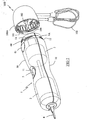
- FIG. 1 shows a household appliance comprising a housing 1 of elongate shape, one longitudinal end of which is intended to be coupled to an accessory, such as a beater accessory 100.
- the housing 1 comprises a body of circular section constituted by two shells 10 of plastics material assembled one on the other and comprises, in the central portion of the housing 1, a manual gripping zone having a restricted section.
- the housing 1 encloses a motor 2 connected to a gearbox 3 by a transmission shaft, shown in dashed lines in FIG. 1, the gearbox 3 being provided with a rotary gearing 31 with two speeds arranged facing each other. an opening in the partition closing the end of the housing 1 to be coupled to the accessory.
- the opposite end of the housing 1 comprises an opening for the passage of a power supply cord 4.
- the operation of the engine 2 is controlled by a control button 5 disposed at the central part of the housing 1, the body of the housing 1 having at this location an impression 11 adapted to the shape of a thumb whose bottom is formed by the actuating surface of the control knob 5.
- the end of the casing 1 intended to be coupled to the beater accessory 100 is provided with an assembly sleeve 1A having a reduced section relative to the gripping zone of the casing 1 so that a shoulder 12 serving axial stop to the accessory 100 when mounted on the housing 1.
- the assembly sleeve 1A comprises four threads 13 quarter turn evenly distributed on the periphery of the coupling sleeve 1A, these threads 13 for coupling by screwing the drummer accessory 100 on the housing 1 in four positions offset from each other by 90 °.
- the beater accessory 100 is provided with a sleeve 100A of plastic assembly engaging around the assembly sleeve 1A of the housing 1 and whose inner periphery comprises quarter-turn threads 101 adapted to cooperate with the threads 13 of the housing 1.
- the assembly sleeve 100A has an outside diameter adapted to continuously extend the body of the housing 1 when the edge of the sleeve 100A abuts against the shoulder 12 of the housing 1.
- the beater accessory 100 also comprises an input shaft 102 which couples with the rotary driver 31 of the gearbox, this input shaft 102 being connected, via a gear train, to two whips 103 oriented parallel to each other and transversely to the shaft 102.
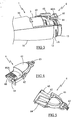
- the immobilization of the beater accessory 100 in its final position is ensured by a locking member 6 comprising a gear element 60 disposed through an opening of the assembly sleeve 1A, the toothed element 60 having longitudinal teeth 60A elastically projecting outside the body of the housing 1 so as to cooperate with locking ribs 104 formed, approximately every 15 °, on the inner periphery of the assembly sleeve 100A of the drummer accessory 100.
- the locking member 6 also comprises an unlocking button 61 disposed in an opening of the body of the casing 1, at the edge of the assembly sleeve 1A.
- the front part of the unlocking button 61 is connected to the gear element 60 by a connecting element 62, the unlocking button 61 allowing when it is depressed, the erasing of the teeth 60A inside the body of the housing 1.
- the locking member 6 also comprises a support tongue 63 extending from the rear part of the unlocking button 61 and whose bent end bears against the body of the gearbox 3 and serves as a pivot point at the locking member 6.
- the elastic return of the toothed element 60 in the locked position is provided by an elastic tongue 64 integrated with the locking member 6.
- the elastic tongue 64 extends obliquely under the connecting element 62 and has a gripping end support on the body of the gearbox 3, under the gear element 60, the gear 3 having at this location a reduced diameter.
- the toothed element 60 extends transversely in a generally circular arc shape that matches the curvature of the body of the casing 1 and preferably on an angular opening greater than 15 ° so that at least two locking ribs 104 are permanently engaged on the gear element 60 when the accessory 100 is coupled to the housing 1.
- flanks of the teeth 60A of the toothed element 60 and the locking ribs 104 coming into contact with each other in the unscrewing direction extend substantially radially to the screw axis in such a way that to prevent the unscrewing of the accessory 100.
- the flanks of the teeth 60A of the gear element 60 and the locking ribs 104 coming into contact with each other when screwing the accessory are inclined so as to generate a radial force leading to the automatic erasure of the gear element 60 inside the housing body during screwing of the accessory 100.
- the distribution of the teeth 60A on the gear element 60 is such that it allows the engagement of a locking rib 104 between two teeth 60A every 5 ° approximately.
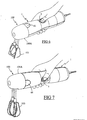
- FIGS. 6 and 7 respectively illustrate, by way of example, the use of the housing with the control button facing upwards and to the side.
- the tight distribution of the teeth 60A of the toothed element 60 then makes it possible to block the accessory 100 in the final tightening position to within 5 degrees, that is to say in a position where the assembly sleeve 100A of the accessory 100 is applied under stress against the housing 1.
- Such a locking device therefore has the advantage of allowing the immobilization of the accessory on the housing in a position where the body of the accessory bears axially against the body of the housing, which considerably reduces the risks. vibration input of the accessory on the housing.
- Such a device has the further advantage of being independent of manufacturing tolerances or wear of the threads.
- the angular distribution of the teeth on the gear element will preferably be adapted to the value of the thread pitch of the quarter-turn threads used.
- this distribution will be such that the angular fineness of the blocking is less than the angle of rotation of the accessory allowed by the elastic deformation of the materials when the body of the accessory comes to bear against the housing and a couple of usual tightening is applied to the accessory.
- the number of ribs on the body of the accessory and the angular extent of the gear element can be modified so as to vary the number of locking ribs permanently engaged on the gear element when the The accessory is coupled to the housing to provide a predetermined minimum locking torque.
- the apparatus according to the invention can be used with another type of accessory, such as a mixing stand.
- the locking member may be carried by the assembly sleeve belonging to the accessory and the locking ribs will then be carried by the assembly sleeve belonging to the housing of the device. .
Landscapes
- Engineering & Computer Science (AREA)
- Mechanical Engineering (AREA)
- Food Science & Technology (AREA)
- Food-Manufacturing Devices (AREA)
- Cookers (AREA)
- Gear Transmission (AREA)
Claims (8)
- Elektrohaushaltsgerät zur Nahrungsmittelzubereitung, mit einem Zubehörteil (100), wie etwa einem Rührzubehörteil, das abnehmbar an ein Gehäuse (1) angekoppelt ist, in welchem ein Antriebsmotor (2) aufgenommen ist, wobei das Gehäuse (1) und das Zubehörteil (100) jeweils eine Verbindungshülse (1A, 100A) aufweisen, die mit einem Gewinde (13, 101) versehen ist, das das Ankoppeln des Zubehörteils (100) an das Gehäuse (1) durch Zusammenschrauben ermöglicht, dadurch gekennzeichnet, dass es eine Verriegelungsvorrichtung aufweist, die ein von einer der Verbindungshülsen (1A, 100A) getragenes verzahntes Element (60) mit dicht verteilten Zähnen aufweist, wobei mindestens einer der Zähne des verzahnten Elements (60) mit mindestens einer von der anderen Verbindungshülse (100A, 1A) getragenen Blockierungsrippe (104) zusammenwirkt, um das Zubehörteil (100) in einer Position am Gehäuse (1) zu blockieren, in der das Zubehörteil (100) axial am Gehäuse (1) anliegt.
- Elektrohaushaltsgerät nach Anspruch 1, dadurch gekennzeichnet, dass das verzahnte Element (60) bezüglich der Verbindungshülse (1 A, 100A), von der es getragen ist, beweglich ist, wobei das verzahnte Element (60) elastisch in eine Verriegelungsposition zurückgestellt wird, in der die Zähne des Elements (60) bezüglich der Verbindungshülse hervorstehen.
- Elektrohaushaltsgerät nach dem vorhergehenden Anspruch, dadurch gekennzeichnet, dass das verzahnte Element (60) mit einem Entriegelungsknopf (61) fest verbunden ist, der die Zähne des verzahnten Elements (60) in das Innere der Verbindungshülse (1A, 100A), von der es getragen ist, einziehen kann.
- Elektrohaushaltsgerät nach Anspruch 3, dadurch gekennzeichnet, dass der Entriegelungsknopf (61) und das verzahnte Element (60) von ein und demselben Teil (6) getragen sind, wobei das Teil (6) ein Element (64) zur elastischen Rückstellung des verzahnten Elements (60) aufweist.
- Elektrohaushaltsgerät nach einem der Ansprüche 1 bis 4, dadurch gekennzeichnet, dass die Winkelverteilung der Blockierungsrippen (104) und die Winkelausdehnung des verzahnten Elements (60) so vorgesehen sind, dass mindestens eine Rippe (104) permanent dem verzahnten Element (60) gegenüberliegt, wenn das Zubehörteil (100) an das Gehäuse (1) angekoppelt ist.
- Elektrohaushaltsgerät nach einem der Ansprüche 1 bis 5, dadurch gekennzeichnet, dass die Gewinde (13, 101) der Verbindungshülsen (1 A, 100A) durch Vierteldrehungsgewindegänge gebildet sind, die das Ankoppeln des Zubehörteils (100) an das Gehäuse (1) in vier verschiedenen, um 90° voneinander versetzten Positionen ermöglichen.
- Elektrohaushaltsgerät nach einem der Ansprüche 1 bis 6, dadurch gekennzeichnet, dass das Gehäuse (1) einen Körper mit einem länglichen Bereich zum manuellen Ergreifen aufweist, der den Motor (2) umschließt, und ein Längsende besitzt, das die Verbindungshülse (1A) aufweist, wobei das mit der Verbindungshülse (1A) versehene Längsende eine Öffnung aufweist, der ein Drehantrieb gegenüberliegt, welcher von dem Motor (2) angetrieben wird.
- Elektrohaushaltsgerät nach einem der Ansprüche 1 bis 7, dadurch gekennzeichnet, dass das verzahnte Element (60) von der Verbindungshülse (1A) des Gehäuses (1) getragen ist und die Rippen (104) von der Verbindungshülse (100A) des Zubehörteils (100) getragen sind.
Applications Claiming Priority (2)
| Application Number | Priority Date | Filing Date | Title |
|---|---|---|---|
| FR0312915 | 2003-11-04 | ||
| FR0312915A FR2861566B1 (fr) | 2003-11-04 | 2003-11-04 | Appareil electromenager de preparation culinaire comportant un accessoire accouple de maniere amovible sur un boitier |
Publications (2)
| Publication Number | Publication Date |
|---|---|
| EP1529472A1 EP1529472A1 (de) | 2005-05-11 |
| EP1529472B1 true EP1529472B1 (de) | 2007-01-24 |
Family
ID=34429872
Family Applications (1)
| Application Number | Title | Priority Date | Filing Date |
|---|---|---|---|
| EP04356163A Expired - Lifetime EP1529472B1 (de) | 2003-11-04 | 2004-10-08 | Elektrisches Haushaltsgerät zur Nahrungszubereitung mit einer lösbar an einem Gehäuse gekoppelten Zusatzvorrichtung |
Country Status (5)
| Country | Link |
|---|---|
| EP (1) | EP1529472B1 (de) |
| AT (1) | ATE352244T1 (de) |
| DE (1) | DE602004004473D1 (de) |
| ES (1) | ES2278291T3 (de) |
| FR (1) | FR2861566B1 (de) |
Cited By (1)
| Publication number | Priority date | Publication date | Assignee | Title |
|---|---|---|---|---|
| JP2012183206A (ja) * | 2011-03-07 | 2012-09-27 | Tiger Vacuum Bottle Co Ltd | 調理用電動回転装置 |
Families Citing this family (4)
| Publication number | Priority date | Publication date | Assignee | Title |
|---|---|---|---|---|
| DE102005038919A1 (de) * | 2005-08-17 | 2007-03-15 | BSH Bosch und Siemens Hausgeräte GmbH | Elektromotorisches Küchengerät mit elektrischer oder elektronischer Verriegelung |
| TWM342130U (en) * | 2007-11-30 | 2008-10-11 | Tsann Kuen Entpr Co Ltd | Compound food-processor |
| EP2193734A1 (de) * | 2008-12-05 | 2010-06-09 | Koninklijke Philips Electronics N.V. | Kupplungsanordnung, Küchengerät und Handmixer |
| DE102013219836A1 (de) * | 2013-09-30 | 2015-04-02 | BSH Bosch und Siemens Hausgeräte GmbH | Verfahren zur Montage eines Werkzeugs für ein Küchengerät |
Family Cites Families (4)
| Publication number | Priority date | Publication date | Assignee | Title |
|---|---|---|---|---|
| GB741405A (en) * | 1953-10-26 | 1955-11-30 | Smith & Wellstood Ltd | Combined mincer and mixing machine |
| DE1165819B (de) * | 1960-10-26 | 1964-03-19 | Licentia Gmbh | Kuechenmaschine mit bajonettverschlussartiger federbelasteter Kupplung |
| FR2537424B1 (fr) * | 1982-12-09 | 1987-07-24 | Moulinex Sa | Appareil electromenager, tel qu'un mixeur, equipe d'un accessoire batteur amovible |
| GB9903775D0 (en) * | 1999-02-18 | 1999-04-14 | Kenwood Marks Ltd | Tool storage arrangements for domestic appliances |
-
2003
- 2003-11-04 FR FR0312915A patent/FR2861566B1/fr not_active Expired - Fee Related
-
2004
- 2004-10-08 ES ES04356163T patent/ES2278291T3/es not_active Expired - Lifetime
- 2004-10-08 DE DE602004004473T patent/DE602004004473D1/de not_active Expired - Lifetime
- 2004-10-08 AT AT04356163T patent/ATE352244T1/de not_active IP Right Cessation
- 2004-10-08 EP EP04356163A patent/EP1529472B1/de not_active Expired - Lifetime
Cited By (1)
| Publication number | Priority date | Publication date | Assignee | Title |
|---|---|---|---|---|
| JP2012183206A (ja) * | 2011-03-07 | 2012-09-27 | Tiger Vacuum Bottle Co Ltd | 調理用電動回転装置 |
Also Published As
| Publication number | Publication date |
|---|---|
| EP1529472A1 (de) | 2005-05-11 |
| FR2861566A1 (fr) | 2005-05-06 |
| FR2861566B1 (fr) | 2006-02-24 |
| ATE352244T1 (de) | 2007-02-15 |
| DE602004004473D1 (de) | 2007-03-15 |
| ES2278291T3 (es) | 2007-08-01 |
Similar Documents
| Publication | Publication Date | Title |
|---|---|---|
| EP0567853B1 (de) | Haushaltgerät wie ein Mischgerät mit einer Sicherheitsvorrichtung | |
| CA2780167C (fr) | Dispositif de fixation vissant auto-verrouillable et assemblage ainsi equipe | |
| FR2643845A3 (fr) | Tournevis | |
| EP1529471A1 (de) | Stabmixer und eintauchender Haushaltsmischer mit einem solchen Stabmixer | |
| FR2820375A1 (fr) | Dispositif de fixation pour accoudoir amovible et dispositif d'assise comportant un tel dispositif de fixation | |
| FR2891449A1 (fr) | Pied de mixage et mixeur menager de type plongeant muni d'un tel pied de mixage | |
| EP1191870B1 (de) | Elektrisches handrühr- und -mixgerät mit sicherheitseinrichtung | |
| EP2623000A1 (de) | Haushaltsgerät zur Essenszubereitung, das für das Halten in der Hand konzipiert ist | |
| EP1529472B1 (de) | Elektrisches Haushaltsgerät zur Nahrungszubereitung mit einer lösbar an einem Gehäuse gekoppelten Zusatzvorrichtung | |
| FR2771784A1 (fr) | Tete de renvoi reglable, notamment pour un accessoire taille-haies | |
| FR2857841A1 (fr) | Dispositif de reglage en continu de la mouture de condiments dans un moulin | |
| EP2623001B1 (de) | Haushaltsgerät zur Essenszubereitung, das zum Halten in der Hand konzipiert und mit einem aufgesetzten Spritzschutzelement ausgestattet ist | |
| EP1745728B1 (de) | Küchengerät mit rotierendem Werkzeug und spezieller Sicherheitsvorrichtung | |
| BE1014865A3 (fr) | Dispositif de fixation amovible d'un aviron sur une | |
| FR2950850A1 (fr) | Systeme de fixation d'un module pour haut de colonne de direction. | |
| EP0832772A1 (de) | Montagevorrichtung für einen drehbaren Knopf für ein Instrumentenbrett | |
| EP0511911A2 (de) | Befestigungsvorrichtung für Spulen von Magnetventilen | |
| EP1835830B1 (de) | Elektrisches haushaltsgerät zur nahrungszubereitung mit einem getriebemechanismus mit bremselementen | |
| EP4436864B1 (de) | Kurbelsatz für ein fahrrad mit abnehmbaren kurbeln | |
| EP1929195A1 (de) | Träger für bildschirm | |
| FR2693284A1 (fr) | Dispositif de transmission entre un bouton de manÓoeuvre et un organe mené. | |
| FR2929094A1 (fr) | Tete de travail pour appareil electromenager de preparation culinaire prevu pour etre tenu a la main | |
| EP1621116B1 (de) | Vorrichtung zur Herstellung einer Lebensmittelemulsion | |
| EP0111300A2 (de) | Haushaltsgerät, wie etwa ein Mixer, mit abnehmbarem Rührwerkansatz | |
| FR2845879A1 (fr) | Dispositif de fixation d'un jouet sur un siege d'enfant, et ensemble comprenant un tel dispositif et au moins un jouet |
Legal Events
| Date | Code | Title | Description |
|---|---|---|---|
| PUAI | Public reference made under article 153(3) epc to a published international application that has entered the european phase |
Free format text: ORIGINAL CODE: 0009012 |
|
| AK | Designated contracting states |
Kind code of ref document: A1 Designated state(s): AT BE BG CH CY CZ DE DK EE ES FI FR GB GR HU IE IT LI LU MC NL PL PT RO SE SI SK TR |
|
| AX | Request for extension of the european patent |
Extension state: AL HR LT LV MK |
|
| 17P | Request for examination filed |
Effective date: 20051108 |
|
| AKX | Designation fees paid |
Designated state(s): AT BE BG CH CY CZ DE DK EE ES FI FR GB GR HU IE IT LI LU MC NL PL PT RO SE SI SK TR |
|
| GRAP | Despatch of communication of intention to grant a patent |
Free format text: ORIGINAL CODE: EPIDOSNIGR1 |
|
| GRAS | Grant fee paid |
Free format text: ORIGINAL CODE: EPIDOSNIGR3 |
|
| GRAA | (expected) grant |
Free format text: ORIGINAL CODE: 0009210 |
|
| AK | Designated contracting states |
Kind code of ref document: B1 Designated state(s): AT BE BG CH CY CZ DE DK EE ES FI FR GB GR HU IE IT LI LU MC NL PL PT RO SE SI SK TR |
|
| PG25 | Lapsed in a contracting state [announced via postgrant information from national office to epo] |
Ref country code: NL Free format text: LAPSE BECAUSE OF FAILURE TO SUBMIT A TRANSLATION OF THE DESCRIPTION OR TO PAY THE FEE WITHIN THE PRESCRIBED TIME-LIMIT Effective date: 20070124 Ref country code: SI Free format text: LAPSE BECAUSE OF FAILURE TO SUBMIT A TRANSLATION OF THE DESCRIPTION OR TO PAY THE FEE WITHIN THE PRESCRIBED TIME-LIMIT Effective date: 20070124 Ref country code: IE Free format text: LAPSE BECAUSE OF FAILURE TO SUBMIT A TRANSLATION OF THE DESCRIPTION OR TO PAY THE FEE WITHIN THE PRESCRIBED TIME-LIMIT Effective date: 20070124 Ref country code: AT Free format text: LAPSE BECAUSE OF FAILURE TO SUBMIT A TRANSLATION OF THE DESCRIPTION OR TO PAY THE FEE WITHIN THE PRESCRIBED TIME-LIMIT Effective date: 20070124 Ref country code: PL Free format text: LAPSE BECAUSE OF FAILURE TO SUBMIT A TRANSLATION OF THE DESCRIPTION OR TO PAY THE FEE WITHIN THE PRESCRIBED TIME-LIMIT Effective date: 20070124 Ref country code: DK Free format text: LAPSE BECAUSE OF FAILURE TO SUBMIT A TRANSLATION OF THE DESCRIPTION OR TO PAY THE FEE WITHIN THE PRESCRIBED TIME-LIMIT Effective date: 20070124 Ref country code: FI Free format text: LAPSE BECAUSE OF FAILURE TO SUBMIT A TRANSLATION OF THE DESCRIPTION OR TO PAY THE FEE WITHIN THE PRESCRIBED TIME-LIMIT Effective date: 20070124 |
|
| REG | Reference to a national code |
Ref country code: GB Ref legal event code: FG4D Free format text: NOT ENGLISH |
|
| REG | Reference to a national code |
Ref country code: CH Ref legal event code: EP |
|
| REG | Reference to a national code |
Ref country code: IE Ref legal event code: FG4D Free format text: LANGUAGE OF EP DOCUMENT: FRENCH |
|
| REF | Corresponds to: |
Ref document number: 602004004473 Country of ref document: DE Date of ref document: 20070315 Kind code of ref document: P |
|
| GBT | Gb: translation of ep patent filed (gb section 77(6)(a)/1977) |
Effective date: 20070319 |
|
| PG25 | Lapsed in a contracting state [announced via postgrant information from national office to epo] |
Ref country code: SE Free format text: LAPSE BECAUSE OF FAILURE TO SUBMIT A TRANSLATION OF THE DESCRIPTION OR TO PAY THE FEE WITHIN THE PRESCRIBED TIME-LIMIT Effective date: 20070424 |
|
| PG25 | Lapsed in a contracting state [announced via postgrant information from national office to epo] |
Ref country code: BG Free format text: LAPSE BECAUSE OF FAILURE TO SUBMIT A TRANSLATION OF THE DESCRIPTION OR TO PAY THE FEE WITHIN THE PRESCRIBED TIME-LIMIT Effective date: 20070425 |
|
| PG25 | Lapsed in a contracting state [announced via postgrant information from national office to epo] |
Ref country code: PT Free format text: LAPSE BECAUSE OF FAILURE TO SUBMIT A TRANSLATION OF THE DESCRIPTION OR TO PAY THE FEE WITHIN THE PRESCRIBED TIME-LIMIT Effective date: 20070625 |
|
| NLV1 | Nl: lapsed or annulled due to failure to fulfill the requirements of art. 29p and 29m of the patents act | ||
| REG | Reference to a national code |
Ref country code: ES Ref legal event code: FG2A Ref document number: 2278291 Country of ref document: ES Kind code of ref document: T3 |
|
| REG | Reference to a national code |
Ref country code: IE Ref legal event code: FD4D |
|
| PG25 | Lapsed in a contracting state [announced via postgrant information from national office to epo] |
Ref country code: SK Free format text: LAPSE BECAUSE OF FAILURE TO SUBMIT A TRANSLATION OF THE DESCRIPTION OR TO PAY THE FEE WITHIN THE PRESCRIBED TIME-LIMIT Effective date: 20070124 |
|
| PLBE | No opposition filed within time limit |
Free format text: ORIGINAL CODE: 0009261 |
|
| STAA | Information on the status of an ep patent application or granted ep patent |
Free format text: STATUS: NO OPPOSITION FILED WITHIN TIME LIMIT |
|
| 26N | No opposition filed |
Effective date: 20071025 |
|
| PG25 | Lapsed in a contracting state [announced via postgrant information from national office to epo] |
Ref country code: RO Free format text: LAPSE BECAUSE OF FAILURE TO SUBMIT A TRANSLATION OF THE DESCRIPTION OR TO PAY THE FEE WITHIN THE PRESCRIBED TIME-LIMIT Effective date: 20070124 Ref country code: CZ Free format text: LAPSE BECAUSE OF FAILURE TO SUBMIT A TRANSLATION OF THE DESCRIPTION OR TO PAY THE FEE WITHIN THE PRESCRIBED TIME-LIMIT Effective date: 20070124 |
|
| PG25 | Lapsed in a contracting state [announced via postgrant information from national office to epo] |
Ref country code: DE Free format text: LAPSE BECAUSE OF FAILURE TO SUBMIT A TRANSLATION OF THE DESCRIPTION OR TO PAY THE FEE WITHIN THE PRESCRIBED TIME-LIMIT Effective date: 20070425 |
|
| BERE | Be: lapsed |
Owner name: SEB S.A. Effective date: 20071031 |
|
| PG25 | Lapsed in a contracting state [announced via postgrant information from national office to epo] |
Ref country code: GR Free format text: LAPSE BECAUSE OF FAILURE TO SUBMIT A TRANSLATION OF THE DESCRIPTION OR TO PAY THE FEE WITHIN THE PRESCRIBED TIME-LIMIT Effective date: 20070425 |
|
| PG25 | Lapsed in a contracting state [announced via postgrant information from national office to epo] |
Ref country code: MC Free format text: LAPSE BECAUSE OF NON-PAYMENT OF DUE FEES Effective date: 20071031 |
|
| PG25 | Lapsed in a contracting state [announced via postgrant information from national office to epo] |
Ref country code: BE Free format text: LAPSE BECAUSE OF NON-PAYMENT OF DUE FEES Effective date: 20071031 |
|
| REG | Reference to a national code |
Ref country code: FR Ref legal event code: ST Effective date: 20080630 |
|
| PG25 | Lapsed in a contracting state [announced via postgrant information from national office to epo] |
Ref country code: EE Free format text: LAPSE BECAUSE OF FAILURE TO SUBMIT A TRANSLATION OF THE DESCRIPTION OR TO PAY THE FEE WITHIN THE PRESCRIBED TIME-LIMIT Effective date: 20070124 |
|
| PG25 | Lapsed in a contracting state [announced via postgrant information from national office to epo] |
Ref country code: FR Free format text: LAPSE BECAUSE OF NON-PAYMENT OF DUE FEES Effective date: 20071031 |
|
| REG | Reference to a national code |
Ref country code: CH Ref legal event code: PL |
|
| PG25 | Lapsed in a contracting state [announced via postgrant information from national office to epo] |
Ref country code: CY Free format text: LAPSE BECAUSE OF FAILURE TO SUBMIT A TRANSLATION OF THE DESCRIPTION OR TO PAY THE FEE WITHIN THE PRESCRIBED TIME-LIMIT Effective date: 20070124 |
|
| PG25 | Lapsed in a contracting state [announced via postgrant information from national office to epo] |
Ref country code: LU Free format text: LAPSE BECAUSE OF NON-PAYMENT OF DUE FEES Effective date: 20071008 |
|
| PG25 | Lapsed in a contracting state [announced via postgrant information from national office to epo] |
Ref country code: TR Free format text: LAPSE BECAUSE OF FAILURE TO SUBMIT A TRANSLATION OF THE DESCRIPTION OR TO PAY THE FEE WITHIN THE PRESCRIBED TIME-LIMIT Effective date: 20070124 Ref country code: HU Free format text: LAPSE BECAUSE OF FAILURE TO SUBMIT A TRANSLATION OF THE DESCRIPTION OR TO PAY THE FEE WITHIN THE PRESCRIBED TIME-LIMIT Effective date: 20070725 |
|
| PG25 | Lapsed in a contracting state [announced via postgrant information from national office to epo] |
Ref country code: LI Free format text: LAPSE BECAUSE OF NON-PAYMENT OF DUE FEES Effective date: 20081031 Ref country code: CH Free format text: LAPSE BECAUSE OF NON-PAYMENT OF DUE FEES Effective date: 20081031 |
|
| PGFP | Annual fee paid to national office [announced via postgrant information from national office to epo] |
Ref country code: GB Payment date: 20131010 Year of fee payment: 10 |
|
| PGFP | Annual fee paid to national office [announced via postgrant information from national office to epo] |
Ref country code: ES Payment date: 20141021 Year of fee payment: 11 |
|
| PGFP | Annual fee paid to national office [announced via postgrant information from national office to epo] |
Ref country code: IT Payment date: 20141021 Year of fee payment: 11 |
|
| GBPC | Gb: european patent ceased through non-payment of renewal fee |
Effective date: 20141008 |
|
| PG25 | Lapsed in a contracting state [announced via postgrant information from national office to epo] |
Ref country code: GB Free format text: LAPSE BECAUSE OF NON-PAYMENT OF DUE FEES Effective date: 20141008 |
|
| PG25 | Lapsed in a contracting state [announced via postgrant information from national office to epo] |
Ref country code: IT Free format text: LAPSE BECAUSE OF NON-PAYMENT OF DUE FEES Effective date: 20151008 |
|
| REG | Reference to a national code |
Ref country code: ES Ref legal event code: FD2A Effective date: 20161125 |
|
| PG25 | Lapsed in a contracting state [announced via postgrant information from national office to epo] |
Ref country code: ES Free format text: LAPSE BECAUSE OF NON-PAYMENT OF DUE FEES Effective date: 20151009 |