EP1529472B1 - Electric household appliance for food processing comprising an accessory removably coupled to a housing - Google Patents
Electric household appliance for food processing comprising an accessory removably coupled to a housing Download PDFInfo
- Publication number
- EP1529472B1 EP1529472B1 EP04356163A EP04356163A EP1529472B1 EP 1529472 B1 EP1529472 B1 EP 1529472B1 EP 04356163 A EP04356163 A EP 04356163A EP 04356163 A EP04356163 A EP 04356163A EP 1529472 B1 EP1529472 B1 EP 1529472B1
- Authority
- EP
- European Patent Office
- Prior art keywords
- housing
- accessory
- toothed element
- electrical appliance
- household electrical
- Prior art date
- Legal status (The legal status is an assumption and is not a legal conclusion. Google has not performed a legal analysis and makes no representation as to the accuracy of the status listed.)
- Expired - Lifetime
Links
- 238000010168 coupling process Methods 0.000 claims abstract description 9
- 238000005859 coupling reaction Methods 0.000 claims abstract description 9
- 230000008878 coupling Effects 0.000 abstract description 8
- 238000004519 manufacturing process Methods 0.000 description 4
- 230000005489 elastic deformation Effects 0.000 description 2
- 230000003100 immobilizing effect Effects 0.000 description 2
- 239000000463 material Substances 0.000 description 2
- 229920003023 plastic Polymers 0.000 description 2
- 239000004033 plastic Substances 0.000 description 2
- 238000002360 preparation method Methods 0.000 description 2
- 230000005540 biological transmission Effects 0.000 description 1
- 230000000903 blocking effect Effects 0.000 description 1
- 230000006835 compression Effects 0.000 description 1
- 238000007906 compression Methods 0.000 description 1
- 230000000994 depressogenic effect Effects 0.000 description 1
- 230000004048 modification Effects 0.000 description 1
- 238000012986 modification Methods 0.000 description 1
- 230000003071 parasitic effect Effects 0.000 description 1
- 238000005192 partition Methods 0.000 description 1
- 238000006467 substitution reaction Methods 0.000 description 1
- 210000003813 thumb Anatomy 0.000 description 1
Images

Classifications
-
- A—HUMAN NECESSITIES
- A47—FURNITURE; DOMESTIC ARTICLES OR APPLIANCES; COFFEE MILLS; SPICE MILLS; SUCTION CLEANERS IN GENERAL
- A47J—KITCHEN EQUIPMENT; COFFEE MILLS; SPICE MILLS; APPARATUS FOR MAKING BEVERAGES
- A47J43/00—Implements for preparing or holding food, not provided for in other groups of this subclass
- A47J43/04—Machines for domestic use not covered elsewhere, e.g. for grinding, mixing, stirring, kneading, emulsifying, whipping or beating foodstuffs, e.g. power-driven
- A47J43/06—Machines for domestic use not covered elsewhere, e.g. for grinding, mixing, stirring, kneading, emulsifying, whipping or beating foodstuffs, e.g. power-driven with a plurality of interchangeable working units, e.g. with a single driving-unit
-
- A—HUMAN NECESSITIES
- A47—FURNITURE; DOMESTIC ARTICLES OR APPLIANCES; COFFEE MILLS; SPICE MILLS; SUCTION CLEANERS IN GENERAL
- A47J—KITCHEN EQUIPMENT; COFFEE MILLS; SPICE MILLS; APPARATUS FOR MAKING BEVERAGES
- A47J43/00—Implements for preparing or holding food, not provided for in other groups of this subclass
- A47J43/04—Machines for domestic use not covered elsewhere, e.g. for grinding, mixing, stirring, kneading, emulsifying, whipping or beating foodstuffs, e.g. power-driven
- A47J43/044—Machines for domestic use not covered elsewhere, e.g. for grinding, mixing, stirring, kneading, emulsifying, whipping or beating foodstuffs, e.g. power-driven with tools driven from the top side
- A47J2043/04409—Apparatus of hand held type
- A47J2043/04418—Apparatus of hand held type with housing extending perpendicular, e.g. horizontally, from the tool axis
Definitions
- the present invention relates to the general technical field of electrical household appliances for culinary preparation.
- the present invention relates more particularly to devices comprising an accessory removably coupled to a housing, the housing and the accessory each comprising an assembly sleeve provided with a thread allowing the screw coupling of the accessory to the housing. .
- a household appliance equipped with a mixer accessory which is removably mounted on a mixer housing, the accessory and the housing each comprising an assembly sleeve provided with a thread. allowing the coupling by screwing one on the other.
- Such an appliance is also provided with a lock immobilizing the accessory in a specific position relative to the housing, the lock having a lug movably mounted on one of the sleeves engaging a notch formed on the other sleeve.
- Such a lock has the disadvantage of immobilizing the accessory in a specific position which can not, for reasons of manufacturing tolerances, correspond to the screwing position for which the body of the accessory bears axially against the housing. It follows that with such an apparatus, when the accessory is immobilized by the lock, there is a clearance between the body of the accessory and the housing body that allows the vibration of the body of the accessory relative to the housing during operation of the device. However, such vibrations of the body of the accessory on the housing generate noise that are unpleasant for the user and give a negative impression on the quality of the device.
- the following invention aims to overcome these disadvantages.
- the object of the invention is achieved by an electrical appliance for culinary preparation according to claim 1.
- Such a feature has the advantage of eliminating the appearance of parasitic vibrations of the accessory relative to the housing.
- the toothed element is movable relative to the connecting sleeve supporting it, the toothed element being brought elastically into a locking position in which the teeth of the toothed element make protruding from the coupling sleeve
- Such a characteristic makes it possible to produce an effective locking device that does not generate a significant frictional force between the toothed element and the locking ribs when the accessory is screwed on.
- the gear element is secured to an unlocking button for erasing the teeth of the gear element within the assembly sleeve supporting it.
- the unlocking button and the gear element are carried by the same part, the latter integrating an elastic return element of the gear element.
- Such a characteristic makes it possible to simplify the production of the locking device by limiting the number of parts.
- the angular distribution of the locking ribs and the angular extent of the gear element are such that at least one locking rib is permanently facing the gear element when the The accessory is coupled to the housing.
- Such a feature makes it possible to immobilize the accessory on the housing regardless of the position of the accessory.
- the threads of the assembly sleeves are constituted by quarter-turn threads which allow the coupling of the accessory on the housing according to four different positions, offset from each other by 90 °.
- Such a characteristic has the advantage of offering the choice in the assembly position of the accessory.
- the housing comprises a body comprising an elongate manual grip zone enclosing the motor and has a longitudinal end comprising the connecting sleeve, the latter comprising an opening opposite which is disposed a rotary trainer driven by the engine.
- the gear element is carried by the housing of the assembly sleeve and the ribs are carried by the assembly sleeve of the accessory.
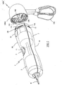
- FIG. 1 shows a household appliance comprising a housing 1 of elongate shape, one longitudinal end of which is intended to be coupled to an accessory, such as a beater accessory 100.
- the housing 1 comprises a body of circular section constituted by two shells 10 of plastics material assembled one on the other and comprises, in the central portion of the housing 1, a manual gripping zone having a restricted section.
- the housing 1 encloses a motor 2 connected to a gearbox 3 by a transmission shaft, shown in dashed lines in FIG. 1, the gearbox 3 being provided with a rotary gearing 31 with two speeds arranged facing each other. an opening in the partition closing the end of the housing 1 to be coupled to the accessory.
- the opposite end of the housing 1 comprises an opening for the passage of a power supply cord 4.
- the operation of the engine 2 is controlled by a control button 5 disposed at the central part of the housing 1, the body of the housing 1 having at this location an impression 11 adapted to the shape of a thumb whose bottom is formed by the actuating surface of the control knob 5.
- the end of the casing 1 intended to be coupled to the beater accessory 100 is provided with an assembly sleeve 1A having a reduced section relative to the gripping zone of the casing 1 so that a shoulder 12 serving axial stop to the accessory 100 when mounted on the housing 1.
- the assembly sleeve 1A comprises four threads 13 quarter turn evenly distributed on the periphery of the coupling sleeve 1A, these threads 13 for coupling by screwing the drummer accessory 100 on the housing 1 in four positions offset from each other by 90 °.
- the beater accessory 100 is provided with a sleeve 100A of plastic assembly engaging around the assembly sleeve 1A of the housing 1 and whose inner periphery comprises quarter-turn threads 101 adapted to cooperate with the threads 13 of the housing 1.
- the assembly sleeve 100A has an outside diameter adapted to continuously extend the body of the housing 1 when the edge of the sleeve 100A abuts against the shoulder 12 of the housing 1.
- the beater accessory 100 also comprises an input shaft 102 which couples with the rotary driver 31 of the gearbox, this input shaft 102 being connected, via a gear train, to two whips 103 oriented parallel to each other and transversely to the shaft 102.
- the immobilization of the beater accessory 100 in its final position is ensured by a locking member 6 comprising a gear element 60 disposed through an opening of the assembly sleeve 1A, the toothed element 60 having longitudinal teeth 60A elastically projecting outside the body of the housing 1 so as to cooperate with locking ribs 104 formed, approximately every 15 °, on the inner periphery of the assembly sleeve 100A of the drummer accessory 100.
- the locking member 6 also comprises an unlocking button 61 disposed in an opening of the body of the casing 1, at the edge of the assembly sleeve 1A.
- the front part of the unlocking button 61 is connected to the gear element 60 by a connecting element 62, the unlocking button 61 allowing when it is depressed, the erasing of the teeth 60A inside the body of the housing 1.
- the locking member 6 also comprises a support tongue 63 extending from the rear part of the unlocking button 61 and whose bent end bears against the body of the gearbox 3 and serves as a pivot point at the locking member 6.
- the elastic return of the toothed element 60 in the locked position is provided by an elastic tongue 64 integrated with the locking member 6.
- the elastic tongue 64 extends obliquely under the connecting element 62 and has a gripping end support on the body of the gearbox 3, under the gear element 60, the gear 3 having at this location a reduced diameter.
- the toothed element 60 extends transversely in a generally circular arc shape that matches the curvature of the body of the casing 1 and preferably on an angular opening greater than 15 ° so that at least two locking ribs 104 are permanently engaged on the gear element 60 when the accessory 100 is coupled to the housing 1.
- flanks of the teeth 60A of the toothed element 60 and the locking ribs 104 coming into contact with each other in the unscrewing direction extend substantially radially to the screw axis in such a way that to prevent the unscrewing of the accessory 100.
- the flanks of the teeth 60A of the gear element 60 and the locking ribs 104 coming into contact with each other when screwing the accessory are inclined so as to generate a radial force leading to the automatic erasure of the gear element 60 inside the housing body during screwing of the accessory 100.
- the distribution of the teeth 60A on the gear element 60 is such that it allows the engagement of a locking rib 104 between two teeth 60A every 5 ° approximately.
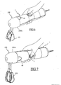
- FIGS. 6 and 7 respectively illustrate, by way of example, the use of the housing with the control button facing upwards and to the side.
- the tight distribution of the teeth 60A of the toothed element 60 then makes it possible to block the accessory 100 in the final tightening position to within 5 degrees, that is to say in a position where the assembly sleeve 100A of the accessory 100 is applied under stress against the housing 1.
- Such a locking device therefore has the advantage of allowing the immobilization of the accessory on the housing in a position where the body of the accessory bears axially against the body of the housing, which considerably reduces the risks. vibration input of the accessory on the housing.
- Such a device has the further advantage of being independent of manufacturing tolerances or wear of the threads.
- the angular distribution of the teeth on the gear element will preferably be adapted to the value of the thread pitch of the quarter-turn threads used.
- this distribution will be such that the angular fineness of the blocking is less than the angle of rotation of the accessory allowed by the elastic deformation of the materials when the body of the accessory comes to bear against the housing and a couple of usual tightening is applied to the accessory.
- the number of ribs on the body of the accessory and the angular extent of the gear element can be modified so as to vary the number of locking ribs permanently engaged on the gear element when the The accessory is coupled to the housing to provide a predetermined minimum locking torque.
- the apparatus according to the invention can be used with another type of accessory, such as a mixing stand.
- the locking member may be carried by the assembly sleeve belonging to the accessory and the locking ribs will then be carried by the assembly sleeve belonging to the housing of the device. .
Landscapes
- Engineering & Computer Science (AREA)
- Mechanical Engineering (AREA)
- Food Science & Technology (AREA)
- Food-Manufacturing Devices (AREA)
- Cookers (AREA)
- Gear Transmission (AREA)
Abstract
Description
La présente invention concerne le domaine technique général des appareils électroménagers de préparation culinaire. La présente invention concerne plus particulièrement les appareils comportant un accessoire accouplé de manière amovible sur un boîtier, le boîtier et l'accessoire comportant chacun un manchon d'assemblage muni d'un filetage permettant l'accouplement par vissage de l'accessoire sur le boîtier.The present invention relates to the general technical field of electrical household appliances for culinary preparation. The present invention relates more particularly to devices comprising an accessory removably coupled to a housing, the housing and the accessory each comprising an assembly sleeve provided with a thread allowing the screw coupling of the accessory to the housing. .
Il est connu, du document EP 0 111 300, un appareil électroménager équipé d'un accessoire batteur qui est monté de manière amovible sur un boîtier de mixeur, l'accessoire et le boîtier comportant chacun un manchon d'assemblage muni d'un filetage permettant l'accouplement par vissage de l'un sur l'autre. Un tel appareil électroménager est également muni d'un verrou immobilisant l'accessoire dans une position déterminée par rapport au boîtier, le verrou comportant un ergot monté mobile sur l'un des manchons venant en prise sur un cran ménagé sur l'autre manchon.It is known, from EP 0 111 300, a household appliance equipped with a mixer accessory which is removably mounted on a mixer housing, the accessory and the housing each comprising an assembly sleeve provided with a thread. allowing the coupling by screwing one on the other. Such an appliance is also provided with a lock immobilizing the accessory in a specific position relative to the housing, the lock having a lug movably mounted on one of the sleeves engaging a notch formed on the other sleeve.
Un tel verrou présente cependant l'inconvénient d'immobiliser l'accessoire dans une position déterminée qui ne peut, pour des questions de tolérances de fabrication, correspondre à la position de vissage pour laquelle le corps de l'accessoire vient en appui axial contre le boîtier. Il s'ensuit qu'avec un tel appareil, lorsque l'accessoire est immobilisé par le verrou, il résulte un jeu entre le corps de l'accessoire et le corps du boîtier qui permet l'entrée en vibration du corps de l'accessoire par rapport au boîtier lors du fonctionnement de l'appareil. Or, de telles vibrations du corps de l'accessoire sur le boîtier génèrent des bruits parasites qui sont désagréables pour l'utilisateur et donnent une impression négative sur la qualité de l'appareil.Such a lock, however, has the disadvantage of immobilizing the accessory in a specific position which can not, for reasons of manufacturing tolerances, correspond to the screwing position for which the body of the accessory bears axially against the housing. It follows that with such an apparatus, when the accessory is immobilized by the lock, there is a clearance between the body of the accessory and the housing body that allows the vibration of the body of the accessory relative to the housing during operation of the device. However, such vibrations of the body of the accessory on the housing generate noise that are unpleasant for the user and give a negative impression on the quality of the device.
L'invention qui suit vise à pallier ces inconvénients.The following invention aims to overcome these disadvantages.
Le but de l'invention est atteint par un appareil électroménager de préparation culinaire selon la revendication 1.The object of the invention is achieved by an electrical appliance for culinary preparation according to
Une telle caractéristique présente l'avantage d'éliminer l'apparition des vibrations parasites de l'accessoire par rapport au boîtier.Such a feature has the advantage of eliminating the appearance of parasitic vibrations of the accessory relative to the housing.
Selon une autre caractéristique de l'invention, l'élément à dentures est mobile par rapport au manchon d'assemblage le supportant, l'élément à dentures étant ramené élastiquement dans une position de verrouillage dans laquelle les dents de l'élément à dentures font saillie par rapport au manchon d'assemblageAccording to another characteristic of the invention, the toothed element is movable relative to the connecting sleeve supporting it, the toothed element being brought elastically into a locking position in which the teeth of the toothed element make protruding from the coupling sleeve
Une telle caractéristique permet de réaliser un dispositif de verrouillage efficace n'engendrant pas d'effort de frottement important entre l'élément à dentures et les nervures de blocage lors du vissage de l'accessoire.Such a characteristic makes it possible to produce an effective locking device that does not generate a significant frictional force between the toothed element and the locking ribs when the accessory is screwed on.
Selon une autre caractéristique de l'invention, l'élément à dentures est solidaire d'un bouton de déverrouillage permettant d'effacer les dents de l'élément à dentures à l'intérieur du manchon d'assemblage le supportant.According to another characteristic of the invention, the gear element is secured to an unlocking button for erasing the teeth of the gear element within the assembly sleeve supporting it.
Une telle caractéristique permet, par une solution simple, de démonter l'accessoire du boîtier sans effort.Such a characteristic makes it possible, by a simple solution, to dismount the accessory from the housing without effort.
Selon une autre caractéristique de l'invention, le bouton de déverrouillage et l'élément à dentures sont portés par une même pièce, cette dernière intégrant un élément de rappel élastique de l'élément à dentures.According to another characteristic of the invention, the unlocking button and the gear element are carried by the same part, the latter integrating an elastic return element of the gear element.
Une telle caractéristique permet de simplifier la réalisation du dispositif de verrouillage en limitant le nombre de pièces.Such a characteristic makes it possible to simplify the production of the locking device by limiting the number of parts.
Selon une autre caractéristique de l'invention, la répartition angulaire des nervures de blocage et l'étendue angulaire de l'élément à dentures sont telles qu'au moins une nervure de blocage est en permanence en regard de l'élément à dentures lorsque l'accessoire est accouplé au boîtier.According to another characteristic of the invention, the angular distribution of the locking ribs and the angular extent of the gear element are such that at least one locking rib is permanently facing the gear element when the The accessory is coupled to the housing.
Une telle caractéristique permet d'assurer une immobilisation de l'accessoire sur le boîtier quelle que soit la position de l'accessoire.Such a feature makes it possible to immobilize the accessory on the housing regardless of the position of the accessory.
Selon une autre caractéristique de l'invention, les filetages des manchons d'assemblage sont constitués par des filets quart de tour qui permettent l'accouplement de l'accessoire sur le boîtier suivant quatre positions différentes, décalées l'une de l'autre de 90°.According to another characteristic of the invention, the threads of the assembly sleeves are constituted by quarter-turn threads which allow the coupling of the accessory on the housing according to four different positions, offset from each other by 90 °.
Une telle caractéristique présente l'avantage d'offrir le choix dans la position d'assemblage de l'accessoire.Such a characteristic has the advantage of offering the choice in the assembly position of the accessory.
Selon encore une autre caractéristique de l'invention, le boîtier comporte un corps comprenant une zone de préhension manuelle de forme allongée renfermant le moteur et présente une extrémité longitudinale comportant le manchon d'assemblage, cette dernière comportant une ouverture en regard de laquelle est disposé un entraîneur rotatif entraîné par le moteur.According to yet another characteristic of the invention, the housing comprises a body comprising an elongate manual grip zone enclosing the motor and has a longitudinal end comprising the connecting sleeve, the latter comprising an opening opposite which is disposed a rotary trainer driven by the engine.
Selon encore une autre caractéristique de l'invention, l'élément à dentures est porté par le manchon d'assemblage du boîtier et les nervures sont portées par le manchon d'assemblage de l'accessoire.According to yet another characteristic of the invention, the gear element is carried by the housing of the assembly sleeve and the ribs are carried by the assembly sleeve of the accessory.
Une telle caractéristique permet d'optimiser les coûts de fabrication des accessoires.Such a characteristic makes it possible to optimize the manufacturing costs of the accessories.
On comprendra mieux les buts, aspects et avantages de la présente invention, d'après la description donnée ci-après d'un mode particulier de réalisation de l'invention présenté à titre d'exemple non limitatif, en se référant aux dessins annexés dans lesquels :
- la figure 1 est une vue en perspective d'un appareil électroménager selon un mode particulier de réalisation de l'invention lorsque l'accessoire batteur est amené en regard du boîtier pour son montage ;
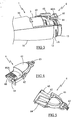
- la figure 2 est une vue en perspective, partiellement arrachée, du boîtier de la figure 1 ;
- la figure 3 est une autre vue en perspective, partiellement arrachée, de la partie avant du boîtier de la figure 1 ;
- les figures 4 et 5 représentent deux vues en perspective de l'organe de verrouillage représenté seul ;
- les figures 6 et 7 illustrent deux exemples d'accouplement de l'accessoire sur le boîtier.
- Figure 1 is a perspective view of an appliance according to a particular embodiment of the invention when the mixer accessory is brought facing the housing for its mounting;
- Figure 2 is a perspective view, partially broken away, of the housing of Figure 1;
- Figure 3 is another perspective view, partially cut away, of the front portion of the housing of Figure 1;
- Figures 4 and 5 show two perspective views of the locking member shown alone;
- Figures 6 and 7 illustrate two examples of coupling of the accessory on the housing.
Seuls les éléments nécessaires à la compréhension de l'invention ont été représentés. Pour faciliter la lecture des dessins les mêmes éléments portent les mêmes références d'une figure à l'autre.Only the elements necessary for the understanding of the invention have been represented. To facilitate the reading of the drawings, the same elements bear the same references from one figure to another.
La figure 1 représente un appareil électroménager comportant un boîtier 1 de forme allongée dont une extrémité longitudinale est destinée à être accouplée à un accessoire, tel un accessoire batteur 100. Le boîtier 1 comporte un corps de section circulaire constitué par deux coquilles 10 en matière plastique assemblées l'une sur l'autre et comprend, dans la partie centrale du boîtier 1, une zone de préhension manuelle présentant une section restreinte.FIG. 1 shows a household appliance comprising a
Conformément aux figures 1 et 2, le boîtier 1 renferme un moteur 2 relié à un réducteur 3 par un arbre de transmission, représentés en pointillés sur la figure 1, le réducteur 3 étant muni d'un entraîneur rotatif 31 à deux vitesses agencé en regard d'une ouverture pratiquée dans la cloison fermant l'extrémité du boîtier 1 destinée à être accouplée à l'accessoire. L'extrémité opposée du boîtier 1 comporte quant à elle une ouverture pour le passage d'un cordon d'alimentation électrique 4.According to FIGS. 1 and 2, the
Le fonctionnement du moteur 2 est contrôlé par un bouton de commande 5 disposé au niveau de la partie centrale du boîtier 1, le corps du boîtier 1 comportant à cet endroit une empreinte 11 adaptée à la forme d'un pouce dont le fond est formé par la surface d'actionnement du bouton de commande 5.The operation of the
L'extrémité du boîtier 1 destinée à être accouplée à l'accessoire batteur 100 est muni d'un manchon d'assemblage 1A présentant une section réduite par rapport à la zone de préhension du boîtier 1 de sorte qu'il résulte un épaulement 12 servant de butée axiale à l'accessoire 100 lors de son montage sur le boîtier 1. Le manchon d'assemblage 1A comporte quatre filets 13 quart de tour régulièrement répartis sur la périphérie du manchon d'assemblage 1A, ces filets 13 permettant l'accouplement par vissage de l'accessoire batteur 100 sur le boîtier 1 suivant quatre positions décalées l'une de l'autre de 90°.The end of the
Conformément à la figure 1, l'accessoire batteur 100 est muni d'un manchon d'assemblage 100A en matière plastique s'engageant autour du manchon d'assemblage 1A du boîtier 1 et dont la périphérie intérieure comporte des filets quart de tour 101 adaptés pour coopérer avec les filets 13 du boîtier 1. Le manchon d'assemblage 100A possède un diamètre extérieur adapté pour prolonger continûment le corps du boîtier 1 lorsque le bord du manchon 100A est en butée contre l'épaulement 12 du boîtier 1.According to FIG. 1, the
L'accessoire batteur 100 comporte également un arbre d'entrée 102 qui vient s'accoupler à l'entraîneur rotatif 31 du réducteur, cet arbre d'entrée 102 étant relié, par l'intermédiaire d'un train d'engrenages, à deux fouets 103 orientés parallèlement l'un à l'autre et transversalement à l'arbre 102.The
Plus particulièrement selon l'invention, l'immobilisation de l'accessoire batteur 100 dans sa position finale est assuré par un organe de verrouillage 6 comprenant un élément à dentures 60 disposé au travers d'une ouverture du manchon d'assemblage 1A, l'élément à dentures 60 comportant des dents 60A longitudinales faisant élastiquement saillie à l'extérieur du corps du boîtier 1 de façon à coopérer avec des nervures de blocage 104 formées, tous les 15° environ, sur la périphérie intérieure du manchon d'assemblage 100A de l'accessoire batteur 100.More particularly according to the invention, the immobilization of the
L'organe de verrouillage 6 comporte également un bouton de déverrouillage 61 disposé dans une ouverture du corps du boîtier 1, en bordure du manchon d'assemblage 1A. La partie avant du bouton de déverrouillage 61 est lié à l'élément à dentures 60 par un élément de liaison 62, le bouton de déverrouillage 61 permettant lorsqu'il est enfoncé, l'effacement des dents 60A à l'intérieur du corps du boîtier 1.The
Conformément aux figures 3 et 5, l'organe de verrouillage 6 comporte également une languette d'appui 63 s'étendant depuis la partie arrière du bouton de déverrouillage 61 et dont l'extrémité recourbée prend appui sur le corps du réducteur 3 et sert de point de pivotement à l'organe de verrouillage 6.According to FIGS. 3 and 5, the
Le rappel élastique de l'élément à dentures 60 en position de verrouillage est assuré par une languette élastique 64 intégrée à l'organe de verrouillage 6. La languette élastique 64 s'étend obliquement sous l'élément de liaison 62 et possède une extrémité prenant appui sur le corps du réducteur 3, sous l'élément à dentures 60, le réducteur 3 présentant à cet endroit un diamètre réduit.The elastic return of the
Comme on peut le voir plus précisément sur les figures 2 ou 4, l'élément à dentures 60 s'étend transversalement suivant une forme générale en arc de cercle qui épouse la courbure du corps du boîtier 1 et préférentiellement sur une ouverture angulaire supérieure à 15° de sorte qu'au moins deux nervures de blocage 104 soit en permanence engagées sur l'élément à dentures 60 lorsque l'accessoire 100 est accouplé au boîtier 1.As can be seen more specifically in FIGS. 2 or 4, the
De manière préférentielle, les flancs des dents 60A de l'élément à dentures 60 et des nervures de blocage 104 venant au contact l'un de l'autre dans le sens du dévissage s'étendent sensiblement radialement à l'axe de vissage de manière à empêcher le dévissage de l'accessoire 100. A l'opposé, les flancs des dents 60A de l'élément à dentures 60 et des nervures de blocage 104 venant au contact l'un de l'autre lors du vissage de l'accessoire sont inclinées de façon à générer un effort radial conduisant à l'effacement automatique de l'élément 60 à dentures à l'intérieur du corps du boîtier lors du vissage de l'accessoire 100.Preferably, the flanks of the
Avantageusement, la répartition des dents 60A sur l'élément à dentures 60 est telle qu'elle permet l'engagement d'une nervure de blocage 104 entre deux dents 60A tous les 5° environ.Advantageously, the distribution of the
Le fonctionnement du dispositif de verrouillage de l'accessoire sur le boîtier va maintenant être décrit.The operation of the locking device of the accessory on the housing will now be described.
Lorsque l'utilisateur souhaite utiliser l'appareil électroménager avec l'accessoire batteur 100, il assemble ce dernier par vissage sur le boîtier 1. Lors de cette opération d'assemblage, l'utilisateur a le choix entre 4 positions de vissage de l'accessoire 100, décalées l'une de l'autre de 90°, ce qui lui permet de choisir l'orientation du bouton de commande 5 qui lui convient le mieux. Ainsi, les figures 6 et 7 illustrent respectivement, à titre d'exemples, l'utilisation du boîtier avec le bouton de commande orienté vers le haut et sur le côté.When the user wishes to use the appliance with the
Lors de l'opération de vissage de l'accessoire 100 sur le boîtier 1, les dents 60A de l'élément 60 viennent s'engager sur les nervures 104 du manchon d'assemblage 100A, et l'élément à dentures 60 s'efface automatiquement dans le corps du boîtier 1, par compression de la languette élastique 64, sous l'effort radial généré par l'inclinaison des flans des dents 60A et des nervures 104 qui sont mutuellement en contact dans le sens du vissage. Lorsque le bord du manchon d'assemblage 100A de l'accessoire arrive en butée contre l'épaulement 12 du boîtier 1, le couple de vissage appliqué par l'utilisateur génère un effort axial de compression de l'accessoire batteur 100 sur le corps du boîtier 1 qui provoque une déformation élastique imperceptible des manchons d'assemblage 1A,100A. La répartition serrée des dents 60A de l'élément à denture 60 permet alors de bloquer l'accessoire 100 dans la position finale de vissage à 5 degrés près, c'est à dire dans une position où le manchon d'assemblage 100A de l'accessoire 100 est appliquée sous contrainte contre le boîtier 1.During the operation of screwing the
Un tel dispositif de verrouillage présente donc l'avantage de permettre l'immobilisation de l'accessoire sur le boîtier dans une position où le corps de l'accessoire est en appui axial contre le corps du boîtier, ce qui permet de réduire considérablement les risques d'entrée en vibration de l'accessoire sur le boîtier. Un tel dispositif présente de plus l'avantage d'être indépendant des tolérances de fabrication ou de l'usure des filetages.Such a locking device therefore has the advantage of allowing the immobilization of the accessory on the housing in a position where the body of the accessory bears axially against the body of the housing, which considerably reduces the risks. vibration input of the accessory on the housing. Such a device has the further advantage of being independent of manufacturing tolerances or wear of the threads.
Bien entendu, la répartition angulaire des dents sur l'élément à dentures sera préférentiellement adaptée à la valeur du pas de vis des filets quart de tour utilisés. Ainsi, cette répartition sera telle que la finesse angulaire du blocage soit inférieure à l'angle de rotation de l'accessoire permis par la déformation élastique des matériaux lorsque le corps de l'accessoire arrive en appui contre le boîtier et qu'un couple de serrage usuel est appliqué sur l'accessoire. De même, le nombre de nervures sur le corps de l'accessoire et l'étendue angulaire de l'élément à dentures pourront être modifiés de manière à faire varier le nombre de nervures de blocage engagées en permanence sur l'élément à dentures lorsque l'accessoire est accouplé au boîtier afin d'assurer un couple de blocage minimum prédéterminé.Of course, the angular distribution of the teeth on the gear element will preferably be adapted to the value of the thread pitch of the quarter-turn threads used. Thus, this distribution will be such that the angular fineness of the blocking is less than the angle of rotation of the accessory allowed by the elastic deformation of the materials when the body of the accessory comes to bear against the housing and a couple of usual tightening is applied to the accessory. Similarly, the number of ribs on the body of the accessory and the angular extent of the gear element can be modified so as to vary the number of locking ribs permanently engaged on the gear element when the The accessory is coupled to the housing to provide a predetermined minimum locking torque.
Bien entendu, l'invention n'est nullement limitée au mode de réalisation décrit et illustré qui n'a été donné qu'à titre d'exemple. Des modifications restent possibles, notamment du point de vue de la constitution des divers éléments ou par substitution d'équivalents techniques, sans sortir pour autant du domaine de protection de l'invention tel que défini dans les revendications.Of course, the invention is not limited to the embodiment described and illustrated which has been given by way of example. Modifications remain possible, particularly from the point of view of the constitution of the various elements or by substitution of technical equivalents, without departing from the scope of protection of the invention as defined in the claims.
Ainsi, l'appareil selon l'invention pourra être utilisé avec un autre type d'accessoire, tel un pied de mixage.Thus, the apparatus according to the invention can be used with another type of accessory, such as a mixing stand.
Ainsi, dans une variante de réalisation non représentée, l'organe de verrouillage pourra être porté par le manchon d'assemblage appartenant à l'accessoire et les nervures de blocage seront alors portées par le manchon d'assemblage appartenant au boîtier de l'appareil.Thus, in a variant embodiment not shown, the locking member may be carried by the assembly sleeve belonging to the accessory and the locking ribs will then be carried by the assembly sleeve belonging to the housing of the device. .
Claims (8)
- A household electrical appliance for preparing food and that comprises an accessory (100), such as a beater accessory, coupled removably to a housing (1) containing a drive motor (2), said housing (1) and said accessory (100) each including an assembly sleeve (1A, 100A) that is provided with a thread (13, 101) enabling the accessory (100) to be coupled to the housing (1) by screw-coupling, said household electrical appliance being characterized in that it includes a locking device including a toothed element (60) whose teeth are distributed close together and that is carried by one of the assembly sleeves (1 A, 100A), at least one of the teeth of said toothed element (60) cooperating with at least one locking rib (104) that is carried by the other assembly sleeve (100A, 1A) so as to hold the accessory (100) stationary on the housing (1) in a position in which the accessory (100) is in axial abutment against the housing (1).
- A household electrical appliance according to claim 1, characterized in that the toothed element (60) is mounted to move relative to the assembly sleeve (1A, 100A) that supports it, said toothed element (60) being urged resiliently back into a locking position in which the teeth of the element (60) project relative to said assembly sleeve.
- A household electrical appliance according to the preceding claim, characterized in that the toothed element (60) is secured to or integral with an unlocking button (61) enabling the teeth of the toothed element (60) to be retracted into the assembly sleeve (1A, 100A) that supports it.
- A household electrical appliance according to claim 3, characterized in that the unlocking button (61) and the toothed element (60) are carried by the same part (6), said part (6) including a resilient return element (64) for resiliently returning the toothed element (60).
- A household electrical appliance according to any one of claims 1 to 4, characterized in that the distribution angle at which the locking ribs (104) are spaced apart and the angle through which the toothed element (60) extends are such that at least one rib (104) is continuously in register with the toothed element (60) when the accessory (100) is coupled to the housing (1).
- A household electrical appliance according to any one of claims 1 to 5, characterized in that the threads (13, 101) of the assembly sleeves (1A, 100A) are constituted by quarter-turn thread starts that enable the accessory (100) to be coupled to the housing (1) in four different positions that are offset from one another by 90°.
- A household electrical appliance according to any one of claims 1 to 6, characterized in that the housing (1) comprises an elongate body enclosing said motor (2) and having a graspable zone for being held in the hand, and has one of its longitudinal ends provided with the assembly sleeve (1A), said longitudinal end that is provided with the assembly sleeve (1A) being provided with an opening disposed facing a rotary chuck that is driven by said motor (2).
- A household electrical appliance according to any one of claims 1 to 7, characterized in that the toothed element (60) is carried by the assembly sleeve (1A) of the housing (1), and in that the ribs (104) are carried by the assembly sleeve (100A) of the accessory (100).
Applications Claiming Priority (2)
| Application Number | Priority Date | Filing Date | Title |
|---|---|---|---|
| FR0312915 | 2003-11-04 | ||
| FR0312915A FR2861566B1 (en) | 2003-11-04 | 2003-11-04 | CULINARY PREPARATION ELECTRICAL APPLIANCE COMPRISING A REMOVABLE COUPLING ACCESSORY ON A HOUSING |
Publications (2)
| Publication Number | Publication Date |
|---|---|
| EP1529472A1 EP1529472A1 (en) | 2005-05-11 |
| EP1529472B1 true EP1529472B1 (en) | 2007-01-24 |
Family
ID=34429872
Family Applications (1)
| Application Number | Title | Priority Date | Filing Date |
|---|---|---|---|
| EP04356163A Expired - Lifetime EP1529472B1 (en) | 2003-11-04 | 2004-10-08 | Electric household appliance for food processing comprising an accessory removably coupled to a housing |
Country Status (5)
| Country | Link |
|---|---|
| EP (1) | EP1529472B1 (en) |
| AT (1) | ATE352244T1 (en) |
| DE (1) | DE602004004473D1 (en) |
| ES (1) | ES2278291T3 (en) |
| FR (1) | FR2861566B1 (en) |
Cited By (1)
| Publication number | Priority date | Publication date | Assignee | Title |
|---|---|---|---|---|
| JP2012183206A (en) * | 2011-03-07 | 2012-09-27 | Tiger Vacuum Bottle Co Ltd | Electrical rotary food processing device |
Families Citing this family (4)
| Publication number | Priority date | Publication date | Assignee | Title |
|---|---|---|---|---|
| DE102005038919A1 (en) | 2005-08-17 | 2007-03-15 | BSH Bosch und Siemens Hausgeräte GmbH | Electric motor kitchen appliance with electrical or electronic interlock |
| TWM342130U (en) * | 2007-11-30 | 2008-10-11 | Tsann Kuen Entpr Co Ltd | Compound food-processor |
| EP2193734A1 (en) * | 2008-12-05 | 2010-06-09 | Koninklijke Philips Electronics N.V. | Coupling assembly, kitchen appliance and hand blender |
| DE102013219836A1 (en) * | 2013-09-30 | 2015-04-02 | BSH Bosch und Siemens Hausgeräte GmbH | Method for assembling a tool for a kitchen appliance |
Family Cites Families (4)
| Publication number | Priority date | Publication date | Assignee | Title |
|---|---|---|---|---|
| GB741405A (en) * | 1953-10-26 | 1955-11-30 | Smith & Wellstood Ltd | Combined mincer and mixing machine |
| DE1165819B (en) * | 1960-10-26 | 1964-03-19 | Licentia Gmbh | Kitchen machine with a bayonet lock-like spring-loaded coupling |
| FR2537424B1 (en) * | 1982-12-09 | 1987-07-24 | Moulinex Sa | HOUSEHOLD APPLIANCE, SUCH AS A MIXER, EQUIPPED WITH A REMOVABLE BATTERY ACCESSORY |
| GB9903775D0 (en) * | 1999-02-18 | 1999-04-14 | Kenwood Marks Ltd | Tool storage arrangements for domestic appliances |
-
2003
- 2003-11-04 FR FR0312915A patent/FR2861566B1/en not_active Expired - Fee Related
-
2004
- 2004-10-08 DE DE602004004473T patent/DE602004004473D1/en not_active Expired - Lifetime
- 2004-10-08 EP EP04356163A patent/EP1529472B1/en not_active Expired - Lifetime
- 2004-10-08 ES ES04356163T patent/ES2278291T3/en not_active Expired - Lifetime
- 2004-10-08 AT AT04356163T patent/ATE352244T1/en not_active IP Right Cessation
Cited By (1)
| Publication number | Priority date | Publication date | Assignee | Title |
|---|---|---|---|---|
| JP2012183206A (en) * | 2011-03-07 | 2012-09-27 | Tiger Vacuum Bottle Co Ltd | Electrical rotary food processing device |
Also Published As
| Publication number | Publication date |
|---|---|
| FR2861566A1 (en) | 2005-05-06 |
| ES2278291T3 (en) | 2007-08-01 |
| FR2861566B1 (en) | 2006-02-24 |
| ATE352244T1 (en) | 2007-02-15 |
| EP1529472A1 (en) | 2005-05-11 |
| DE602004004473D1 (en) | 2007-03-15 |
Similar Documents
| Publication | Publication Date | Title |
|---|---|---|
| EP0567853B1 (en) | Household appliance, like a mixer equipped with a security device | |
| EP1529471B1 (en) | Mixing rod and domestic mixing device of the immersing type with such a mixing rod | |
| CA2780167C (en) | Self-locking screwing attachment device and assembly provided with same | |
| FR2643845A3 (en) | SCREWDRIVER | |
| FR2820375A1 (en) | FIXING DEVICE FOR A REMOVABLE ARMREST AND SEAT DEVICE COMPRISING SUCH A FIXING DEVICE | |
| FR2891449A1 (en) | Plunger-type food mixer has rotating tool attached to holder that locks inside protective cover when tool is fitted to mixer foot | |
| EP1191870B1 (en) | Electric hand-operated rotary beater/mixer comprising a safety device | |
| EP2623000A1 (en) | Household cooking appliance designed to be hand-held | |
| EP1529472B1 (en) | Electric household appliance for food processing comprising an accessory removably coupled to a housing | |
| FR2771784A1 (en) | ADJUSTABLE RETURN HEAD, ESPECIALLY FOR A HEDGE TRIMMER ACCESSORY | |
| FR2857841A1 (en) | Condiment e.g. pepper, grinding adjusting device for use in e.g. electric mill, has metering sleeve whose rotation leads to translation of basin support part having guiding groove preventing part rotation with respect to retaining ring | |
| EP2623001B1 (en) | Household cooking appliance designed to be hand-held comprising an added façade element | |
| EP1745728B1 (en) | Kitchen device with a rotary tool equipped with a special security mechanism | |
| BE1014865A3 (en) | Removable fixing device for rowing on | |
| EP0832772A1 (en) | Mounting device of a turning knob for an instrument panel | |
| EP0511911A2 (en) | Fastening device for solenoid valve coils | |
| EP1835830B1 (en) | Electrical household appliance for culinary preparation, comprising a transmission mechanism provided with braking means | |
| EP4436864B1 (en) | Crankset for a bicycle with removable cranks | |
| EP1929195A1 (en) | Support for display screen | |
| FR2693284A1 (en) | Transmission device between an operating button and a driven member. | |
| FR2929094A1 (en) | Working head for use in hand-held household culinary preparation apparatus for e.g. cutting carrot, has body including handle with gripping zone extended at proximity of supply spout, and pusher including end with tab extended above handle | |
| EP1621116B1 (en) | Device for the production of a food emulsion | |
| EP0111300A2 (en) | Kitchen appliance, such as a mixer, provided with a removable beating accessory | |
| FR2845879A1 (en) | Support and fastening for toy on child's car seat or stroller comprises curved elastic arms with fixing for toy and ends gripping sides of seat | |
| FR2665096A1 (en) | TOOLING OF A PREDETERMINABLE TIGHTENING TORQUE. |
Legal Events
| Date | Code | Title | Description |
|---|---|---|---|
| PUAI | Public reference made under article 153(3) epc to a published international application that has entered the european phase |
Free format text: ORIGINAL CODE: 0009012 |
|
| AK | Designated contracting states |
Kind code of ref document: A1 Designated state(s): AT BE BG CH CY CZ DE DK EE ES FI FR GB GR HU IE IT LI LU MC NL PL PT RO SE SI SK TR |
|
| AX | Request for extension of the european patent |
Extension state: AL HR LT LV MK |
|
| 17P | Request for examination filed |
Effective date: 20051108 |
|
| AKX | Designation fees paid |
Designated state(s): AT BE BG CH CY CZ DE DK EE ES FI FR GB GR HU IE IT LI LU MC NL PL PT RO SE SI SK TR |
|
| GRAP | Despatch of communication of intention to grant a patent |
Free format text: ORIGINAL CODE: EPIDOSNIGR1 |
|
| GRAS | Grant fee paid |
Free format text: ORIGINAL CODE: EPIDOSNIGR3 |
|
| GRAA | (expected) grant |
Free format text: ORIGINAL CODE: 0009210 |
|
| AK | Designated contracting states |
Kind code of ref document: B1 Designated state(s): AT BE BG CH CY CZ DE DK EE ES FI FR GB GR HU IE IT LI LU MC NL PL PT RO SE SI SK TR |
|
| PG25 | Lapsed in a contracting state [announced via postgrant information from national office to epo] |
Ref country code: NL Free format text: LAPSE BECAUSE OF FAILURE TO SUBMIT A TRANSLATION OF THE DESCRIPTION OR TO PAY THE FEE WITHIN THE PRESCRIBED TIME-LIMIT Effective date: 20070124 Ref country code: SI Free format text: LAPSE BECAUSE OF FAILURE TO SUBMIT A TRANSLATION OF THE DESCRIPTION OR TO PAY THE FEE WITHIN THE PRESCRIBED TIME-LIMIT Effective date: 20070124 Ref country code: IE Free format text: LAPSE BECAUSE OF FAILURE TO SUBMIT A TRANSLATION OF THE DESCRIPTION OR TO PAY THE FEE WITHIN THE PRESCRIBED TIME-LIMIT Effective date: 20070124 Ref country code: AT Free format text: LAPSE BECAUSE OF FAILURE TO SUBMIT A TRANSLATION OF THE DESCRIPTION OR TO PAY THE FEE WITHIN THE PRESCRIBED TIME-LIMIT Effective date: 20070124 Ref country code: PL Free format text: LAPSE BECAUSE OF FAILURE TO SUBMIT A TRANSLATION OF THE DESCRIPTION OR TO PAY THE FEE WITHIN THE PRESCRIBED TIME-LIMIT Effective date: 20070124 Ref country code: DK Free format text: LAPSE BECAUSE OF FAILURE TO SUBMIT A TRANSLATION OF THE DESCRIPTION OR TO PAY THE FEE WITHIN THE PRESCRIBED TIME-LIMIT Effective date: 20070124 Ref country code: FI Free format text: LAPSE BECAUSE OF FAILURE TO SUBMIT A TRANSLATION OF THE DESCRIPTION OR TO PAY THE FEE WITHIN THE PRESCRIBED TIME-LIMIT Effective date: 20070124 |
|
| REG | Reference to a national code |
Ref country code: GB Ref legal event code: FG4D Free format text: NOT ENGLISH |
|
| REG | Reference to a national code |
Ref country code: CH Ref legal event code: EP |
|
| REG | Reference to a national code |
Ref country code: IE Ref legal event code: FG4D Free format text: LANGUAGE OF EP DOCUMENT: FRENCH |
|
| REF | Corresponds to: |
Ref document number: 602004004473 Country of ref document: DE Date of ref document: 20070315 Kind code of ref document: P |
|
| GBT | Gb: translation of ep patent filed (gb section 77(6)(a)/1977) |
Effective date: 20070319 |
|
| PG25 | Lapsed in a contracting state [announced via postgrant information from national office to epo] |
Ref country code: SE Free format text: LAPSE BECAUSE OF FAILURE TO SUBMIT A TRANSLATION OF THE DESCRIPTION OR TO PAY THE FEE WITHIN THE PRESCRIBED TIME-LIMIT Effective date: 20070424 |
|
| PG25 | Lapsed in a contracting state [announced via postgrant information from national office to epo] |
Ref country code: BG Free format text: LAPSE BECAUSE OF FAILURE TO SUBMIT A TRANSLATION OF THE DESCRIPTION OR TO PAY THE FEE WITHIN THE PRESCRIBED TIME-LIMIT Effective date: 20070425 |
|
| PG25 | Lapsed in a contracting state [announced via postgrant information from national office to epo] |
Ref country code: PT Free format text: LAPSE BECAUSE OF FAILURE TO SUBMIT A TRANSLATION OF THE DESCRIPTION OR TO PAY THE FEE WITHIN THE PRESCRIBED TIME-LIMIT Effective date: 20070625 |
|
| NLV1 | Nl: lapsed or annulled due to failure to fulfill the requirements of art. 29p and 29m of the patents act | ||
| REG | Reference to a national code |
Ref country code: ES Ref legal event code: FG2A Ref document number: 2278291 Country of ref document: ES Kind code of ref document: T3 |
|
| REG | Reference to a national code |
Ref country code: IE Ref legal event code: FD4D |
|
| PG25 | Lapsed in a contracting state [announced via postgrant information from national office to epo] |
Ref country code: SK Free format text: LAPSE BECAUSE OF FAILURE TO SUBMIT A TRANSLATION OF THE DESCRIPTION OR TO PAY THE FEE WITHIN THE PRESCRIBED TIME-LIMIT Effective date: 20070124 |
|
| PLBE | No opposition filed within time limit |
Free format text: ORIGINAL CODE: 0009261 |
|
| STAA | Information on the status of an ep patent application or granted ep patent |
Free format text: STATUS: NO OPPOSITION FILED WITHIN TIME LIMIT |
|
| 26N | No opposition filed |
Effective date: 20071025 |
|
| PG25 | Lapsed in a contracting state [announced via postgrant information from national office to epo] |
Ref country code: RO Free format text: LAPSE BECAUSE OF FAILURE TO SUBMIT A TRANSLATION OF THE DESCRIPTION OR TO PAY THE FEE WITHIN THE PRESCRIBED TIME-LIMIT Effective date: 20070124 Ref country code: CZ Free format text: LAPSE BECAUSE OF FAILURE TO SUBMIT A TRANSLATION OF THE DESCRIPTION OR TO PAY THE FEE WITHIN THE PRESCRIBED TIME-LIMIT Effective date: 20070124 |
|
| PG25 | Lapsed in a contracting state [announced via postgrant information from national office to epo] |
Ref country code: DE Free format text: LAPSE BECAUSE OF FAILURE TO SUBMIT A TRANSLATION OF THE DESCRIPTION OR TO PAY THE FEE WITHIN THE PRESCRIBED TIME-LIMIT Effective date: 20070425 |
|
| BERE | Be: lapsed |
Owner name: SEB S.A. Effective date: 20071031 |
|
| PG25 | Lapsed in a contracting state [announced via postgrant information from national office to epo] |
Ref country code: GR Free format text: LAPSE BECAUSE OF FAILURE TO SUBMIT A TRANSLATION OF THE DESCRIPTION OR TO PAY THE FEE WITHIN THE PRESCRIBED TIME-LIMIT Effective date: 20070425 |
|
| PG25 | Lapsed in a contracting state [announced via postgrant information from national office to epo] |
Ref country code: MC Free format text: LAPSE BECAUSE OF NON-PAYMENT OF DUE FEES Effective date: 20071031 |
|
| PG25 | Lapsed in a contracting state [announced via postgrant information from national office to epo] |
Ref country code: BE Free format text: LAPSE BECAUSE OF NON-PAYMENT OF DUE FEES Effective date: 20071031 |
|
| REG | Reference to a national code |
Ref country code: FR Ref legal event code: ST Effective date: 20080630 |
|
| PG25 | Lapsed in a contracting state [announced via postgrant information from national office to epo] |
Ref country code: EE Free format text: LAPSE BECAUSE OF FAILURE TO SUBMIT A TRANSLATION OF THE DESCRIPTION OR TO PAY THE FEE WITHIN THE PRESCRIBED TIME-LIMIT Effective date: 20070124 |
|
| PG25 | Lapsed in a contracting state [announced via postgrant information from national office to epo] |
Ref country code: FR Free format text: LAPSE BECAUSE OF NON-PAYMENT OF DUE FEES Effective date: 20071031 |
|
| REG | Reference to a national code |
Ref country code: CH Ref legal event code: PL |
|
| PG25 | Lapsed in a contracting state [announced via postgrant information from national office to epo] |
Ref country code: CY Free format text: LAPSE BECAUSE OF FAILURE TO SUBMIT A TRANSLATION OF THE DESCRIPTION OR TO PAY THE FEE WITHIN THE PRESCRIBED TIME-LIMIT Effective date: 20070124 |
|
| PG25 | Lapsed in a contracting state [announced via postgrant information from national office to epo] |
Ref country code: LU Free format text: LAPSE BECAUSE OF NON-PAYMENT OF DUE FEES Effective date: 20071008 |
|
| PG25 | Lapsed in a contracting state [announced via postgrant information from national office to epo] |
Ref country code: TR Free format text: LAPSE BECAUSE OF FAILURE TO SUBMIT A TRANSLATION OF THE DESCRIPTION OR TO PAY THE FEE WITHIN THE PRESCRIBED TIME-LIMIT Effective date: 20070124 Ref country code: HU Free format text: LAPSE BECAUSE OF FAILURE TO SUBMIT A TRANSLATION OF THE DESCRIPTION OR TO PAY THE FEE WITHIN THE PRESCRIBED TIME-LIMIT Effective date: 20070725 |
|
| PG25 | Lapsed in a contracting state [announced via postgrant information from national office to epo] |
Ref country code: LI Free format text: LAPSE BECAUSE OF NON-PAYMENT OF DUE FEES Effective date: 20081031 Ref country code: CH Free format text: LAPSE BECAUSE OF NON-PAYMENT OF DUE FEES Effective date: 20081031 |
|
| PGFP | Annual fee paid to national office [announced via postgrant information from national office to epo] |
Ref country code: GB Payment date: 20131010 Year of fee payment: 10 |
|
| PGFP | Annual fee paid to national office [announced via postgrant information from national office to epo] |
Ref country code: ES Payment date: 20141021 Year of fee payment: 11 |
|
| PGFP | Annual fee paid to national office [announced via postgrant information from national office to epo] |
Ref country code: IT Payment date: 20141021 Year of fee payment: 11 |
|
| GBPC | Gb: european patent ceased through non-payment of renewal fee |
Effective date: 20141008 |
|
| PG25 | Lapsed in a contracting state [announced via postgrant information from national office to epo] |
Ref country code: GB Free format text: LAPSE BECAUSE OF NON-PAYMENT OF DUE FEES Effective date: 20141008 |
|
| PG25 | Lapsed in a contracting state [announced via postgrant information from national office to epo] |
Ref country code: IT Free format text: LAPSE BECAUSE OF NON-PAYMENT OF DUE FEES Effective date: 20151008 |
|
| REG | Reference to a national code |
Ref country code: ES Ref legal event code: FD2A Effective date: 20161125 |
|
| PG25 | Lapsed in a contracting state [announced via postgrant information from national office to epo] |
Ref country code: ES Free format text: LAPSE BECAUSE OF NON-PAYMENT OF DUE FEES Effective date: 20151009 |