EP1529429A1 - Schutzanordnung - Google Patents
Schutzanordnung Download PDFInfo
- Publication number
- EP1529429A1 EP1529429A1 EP04023863A EP04023863A EP1529429A1 EP 1529429 A1 EP1529429 A1 EP 1529429A1 EP 04023863 A EP04023863 A EP 04023863A EP 04023863 A EP04023863 A EP 04023863A EP 1529429 A1 EP1529429 A1 EP 1529429A1
- Authority
- EP
- European Patent Office
- Prior art keywords
- protective element
- peripheral edge
- end edge
- arrangement according
- protective
- Prior art date
- Legal status (The legal status is an assumption and is not a legal conclusion. Google has not performed a legal analysis and makes no representation as to the accuracy of the status listed.)
- Granted
Links
Images

Classifications
-
- F—MECHANICAL ENGINEERING; LIGHTING; HEATING; WEAPONS; BLASTING
- F16—ENGINEERING ELEMENTS AND UNITS; GENERAL MEASURES FOR PRODUCING AND MAINTAINING EFFECTIVE FUNCTIONING OF MACHINES OR INSTALLATIONS; THERMAL INSULATION IN GENERAL
- F16D—COUPLINGS FOR TRANSMITTING ROTATION; CLUTCHES; BRAKES
- F16D3/00—Yielding couplings, i.e. with means permitting movement between the connected parts during the drive
- F16D3/84—Shrouds, e.g. casings, covers; Sealing means specially adapted therefor
- F16D3/841—Open covers, e.g. guards for agricultural p.t.o. shafts
-
- A—HUMAN NECESSITIES
- A01—AGRICULTURE; FORESTRY; ANIMAL HUSBANDRY; HUNTING; TRAPPING; FISHING
- A01B—SOIL WORKING IN AGRICULTURE OR FORESTRY; PARTS, DETAILS, OR ACCESSORIES OF AGRICULTURAL MACHINES OR IMPLEMENTS, IN GENERAL
- A01B71/00—Construction or arrangement of setting or adjusting mechanisms, of implement or tool drive or of power take-off; Means for protecting parts against dust, or the like; Adapting machine elements to or for agricultural purposes
- A01B71/08—Means for protecting against dust or the like, or for cleaning agricultural implements
-
- Y—GENERAL TAGGING OF NEW TECHNOLOGICAL DEVELOPMENTS; GENERAL TAGGING OF CROSS-SECTIONAL TECHNOLOGIES SPANNING OVER SEVERAL SECTIONS OF THE IPC; TECHNICAL SUBJECTS COVERED BY FORMER USPC CROSS-REFERENCE ART COLLECTIONS [XRACs] AND DIGESTS
- Y10—TECHNICAL SUBJECTS COVERED BY FORMER USPC
- Y10S—TECHNICAL SUBJECTS COVERED BY FORMER USPC CROSS-REFERENCE ART COLLECTIONS [XRACs] AND DIGESTS
- Y10S56/00—Harvesters
- Y10S56/24—Harvester guards
Definitions
- Such protective arrangements serve as shock protection and are connected via connecting means held stationary so that the enclosed by the protective device Can rotate the joint in it.
- the protective device does not rotate and should make contact Avoid persons with rotating components.
- the protection arrangement comprises a first protective element with an annular portion with a first end edge and is on its outer periphery with first attachment means provided in the form of a collar. It is an annular second protection element provided in the form of a connection element. Between the first protection element and the second protection element, a third protection element is arranged is made of an elastomer and hook-like at a first annular end first connection means for connection to the first attachment means in Form of the collar has. At a second annular end of the third Protective element are second connecting means for connection to the second fastening means provided on the connection element.
- the connecting element has a Seat as a second fastening means, on which a third protective element associated collar, which is slotted and reduced in diameter by means of screws can be fixed as a second connection means.
- the third protection element is in the region between the first annular end and the second annular end designed with a fold, wherein the first attachment end and the second attachment end is designed differently in terms of diameter.
- the Fold runs in a radial section with respect to the longitudinal axis and is either ever after bending of the joint stretched on a part of the circumference and on one further part of the circumference compressed.
- the jacket section can also have a lattice structure and forms at least one fold.
- An advantage of this training is that all around a secure bracket between the third protection element and the first protection element on the one hand and the third Protective element and the second protective element is given on the other hand, wherein It also ensures that a release practically only by using tools is possible, so that unintentional removal of the third protective element, the one To provide protection against intrusion, as far as possible avoided and only knowingly with the use of tools can be removed if a repair or Maintenance is to be made on the joint or on components of the protective arrangement.
- the first protective element associated first retaining lugs in their near the first end edge area in Circumferential direction of the outer periphery are formed longer than in the first Front edge removed third peripheral edge portion. This measure causes both in the stretching as well as in the compression of the shell portion of the third Protective element a favorable force.
- the retaining lugs in the first end edge near area in the circumferential direction of the outer periphery of the associated Protective element laterally by parallel and groove-free first peripheral edge portions and then from the front edge away with each other extending second peripheral edge portions are provided with a groove.
- a favorable introduction of force results in particular when the running towards each other second peripheral edge portions through a third peripheral edge portion are connected in the form of a bow portion which also has a groove.
- first protective element or in particular The second protective element associated first or second retaining lugs preferably have an approximately rectangular basic shape in a plan view, wherein the circumferential direction of the outer periphery of the associated protective element parallel peripheral edge portions are formed shorter than those parallel to a circumferential edge regions extending from the associated protective element. It is advantageous if the connection to the holding approaches provided holding sections in the circumferential direction by a respective retaining web include separate breakthroughs. This results in a kind of lattice structure.
- a favorable power distribution is achieved when the first breakthroughs component of circumferentially distributed according to the first holding lugs arranged tab-shaped first holding sections are.
- the first protective element is diameter-moderate larger than the second protection element.
- the third protection element forms in a radial section seen a fold between the first protective element and the second protection element.
- the jacket section of the third protective element Has breakthroughs or a grid structure.
- a preferred embodiment of the invention is schematically in the drawing shown.
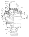
- FIG. 1 a joint in the form of a double universal joint 1 can be seen, wherein the Protection arrangement is shown in the half longitudinal section.
- the double universal joint 1 has a connection fork 2, which via a first spider 3 with the corresponding Fork of a housing 4 is connected.
- This carries another joint fork, which is connected via a second spider 5 with the yoke 6.
- a profile tube 9 connected to that to a displacement arrangement heard and about another profile tube (not shown), which with the Profile tube 9 is connected telescopically and with a further hinge assembly.
- a connection element 7 is attached, which with a Protective tube 8 is connected, which covers the profile tube 9.
- a torque is for example via the connecting fork 2, the housing 4 with the two joint forks and the two spigot 35 on the yoke 6 and from this over the Transfer profile tube to an appropriate arrangement at the other end of the PTO shaft.
- this protective arrangements are provided. These protective arrangements are as resting protection designed, d. H. they are indeed carried by the joint, rotate when driving the same not with this, as they have not shown means be connected to a stationary part of the device.
- the to the protection arrangement belonging components are interconnected so that they are a non-rotatable connection accomplish, so that all components are stationary.
- the protective arrangement according to the invention relates in particular to the cover to be covered Section of a propeller shaft in the region of a joint, for example in Shape of a double universal joint 1.
- the protective arrangement comprises a first protective element 11, for example Plastic that rotates by means of a bearing ring 10 on the housing 4 of the joint 1 is stored. It comprises an annular portion away from the connecting fork 2 12 with the outer periphery 13, the circumferentially distributed first retaining lugs 14 as the first Fasteners are molded.
- Their training is related in the following with the figures 2 and 3 described in more detail.
- connection element 7 There is provided a second protective element 15 which is connected to the connection element 7 is connected or its function may also include.
- the second protection element 15 is provided on its outer circumference 16 with second retaining lugs 17. The training of the same is below with reference to Figures 5 and 6 closer described.
- a third protective element 18 is arranged, which is a first annular End 19 has, with which it to the outer periphery 13 of the first Protective element 11 connects. It has first breakthroughs 20 first Connecting means which are arranged circumferentially distributed about the longitudinal axis X. and cooperate with each of the first holding lugs 14. Their design will be described in more detail in connection with Figure 4 below.
- the third protection element 18 has a second annular end 21 in which second apertures 22 are arranged circumferentially distributed about the longitudinal axis X, the with the second retaining lugs 17 are engaged.
- a skirt portion 23 is provided, which in a radial section, as shown, a fold 23 a forms.
- breakthroughs 24 are distributed beyond.
- the jacket section 23 can also, as in connection with DE 101 53 822 C1, have a lattice structure.
- the openings 24 form Overall, a hole structure.
- the third protection element 18 prevents that between the first protection element 11 and the components of the joint 1 formed free space, for the bending of the joint 1 is required, can be intervened by hand.
- the Hole structure with the apertures 24 is corresponding to prevent such Designed intervention.
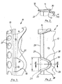
- FIGS 2 to 4 illustrates a part of a development of the annular portion 12.
- the annular portion 12 of the first protection element 11 with the outer periphery 13 terminates in a first end edge 25.
- the outer periphery 13 of this annular Section 12 of the first protective element 11 are circumferentially distributed first retaining lugs 14 formed, which protrude from the outer periphery 13 and in one of the first End edge 25 are arranged near the area.
- the first holding lugs 14 each include a support tabs 26, the over the first end edge 25 protrudes. This has the length L in the circumferential direction. From the support tab 26 extend away, starting from the first end edge 25, first two first peripheral edge portions 27, which are perpendicular to the end edge 25th and extend parallel to each other and extend over the support tabs 26. From each of these go second peripheral edge portions 28 which are consecutive to run and at its end remote from the support tab 26, by an arc section 29 are connected, which forms a third peripheral edge portion. About the second peripheral edge portions 28 and the third peripheral edge portion 29 extends a first groove 30. There are preferably six such retaining lugs 14 provided circumferentially distributed. Of these is only a section with two holding lugs 14 shown in the bend according to Figure 2.
- the first annular end 19 of the third protective element 18 is in FIG Form of a section shown in settlement.
- the third protection element 18 is in rest, so given a sufficient flexibility in bending the joint 1 is made of an elastomer, in particular of a thermoplastic.
- the section shown in Figure 4 comprises two first holding portions 31, the lashing are designed and protrude from the first annular end 19 and in which first openings 20 are provided, the shape of the design the first holding lugs 14 are adjusted.
- the first breakthroughs 32 will be bounded by boundary edge portions 32, 33, with straight portions provided are, with respect to the dimension with the distance L of the mutually parallel first peripheral edge portions 27 of the first retaining lugs 14 arranged are.
- the two boundary edge sections 32 engage in the groove 30.
- Of the Limiting edge portion 33 sits under the support tabs 26 and is located in the assembled state between the bottom of the support tab 26 and the This is the third protective element 18 with the first holding portions 31 held firmly on the first holding lugs 14.
- the parallel first Peripheral edge portions 27 serve to mount the third protection element 18 when engaging the first holding portions 31 with the first holding inserts 14 to facilitate.
- the second protective element 15 is a part of its outer periphery 16 shown as angling or in section.
- the second protection element 15 is also annular and has the second end edge 34, the in the assembled state of the components of the protective arrangement on the hinge 1 of the first End edge 25 is trimmed. This means that the first end edge 25 and the second end edge 34 in the undeflected state of the joint 1 in opposite Directions.
- the outer periphery 16 of the second protective element 15 are a plurality of second retaining lugs 17 formed forming the second fastening means and over the outer circumference 16 are formed protruding outwards.
- the second retaining lugs 17 are provided relatively close to each other on the circumference.
- the second stop approaches 17 are substantially parallel to the end edge 34, but offset from this, each having a first peripheral edge region 35, starting from this between the outer periphery 16 and the first peripheral edge region 35 itself a second groove 36 open in the direction of the second end edge 34 is located.
- a third peripheral edge region is closed 38 and a fourth peripheral edge region 39, from the second Run edge 34 away.
- the associated peripheral portion of the second annular end 21 of the third Protective element 18 forms second holding portions 41, each having a second Breakthrough 22 for each second retaining lug 17 include.
- the second holding sections 41 further comprise between each two circumferentially successive ones second openings 22 a holding web 41 and a peripheral web 42.
- Each second aperture 22 is through parallel boundary edge portions 43 and parallel Limiting edge portions 44 limited to the associated second holding approach 17 are adapted and include a boundary edge portion 43 a, the engages in the groove 36 of the associated second holding lug 17.
- the two boundary edge sections 43 are parallel to each other and are the inner Bounding edge of the second groove 36 and the second peripheral edge region 37, respectively customized.
- the two mutually parallel boundary edge sections 44 cooperate with the third and fourth peripheral edge regions 38, 39.
- the holding webs 41 are between two circumferentially successive second Holding lugs 17 added.
- the peripheral ridge 42 is behind the second Peripheral edge portion 37 of the retaining lugs 17.
- the boundary edge portions 43a in particular secure the seat of the third protective element 18 as well as the boundary edge portion 33 when moving the two End edges 25, 34.
- the other areas secure the seat when tensile forces occur due to an extension of the third protective element 18 in the region of the fold 23a.
Landscapes
- Engineering & Computer Science (AREA)
- General Engineering & Computer Science (AREA)
- Mechanical Engineering (AREA)
- Life Sciences & Earth Sciences (AREA)
- Soil Sciences (AREA)
- Environmental Sciences (AREA)
- Clamps And Clips (AREA)
- Diaphragms And Bellows (AREA)
- Agricultural Machines (AREA)
- Prostheses (AREA)
- Emergency Protection Circuit Devices (AREA)
- Seal Device For Vehicle (AREA)
- Fertilizing (AREA)
Abstract
Description
- ein erstes Schutzelement mit einem ringförmigen Abschnitt mit einer ersten Stirnkante, das auf seinem Außenumfang mit ersten Befestigungsmitteln versehen ist,
- ein ringförmiges zweites Schutzelement, das auf einem Außenumfang zweite Befestigungsmittel und das eine zweite Stirnkante aufweist,
- ein drittes Schutzelement aus einem Elastomer, das an einem ersten ringförmigen Ende erste Verbindungsmittel zur Verbindung mit den ersten Befestigungsmitteln und an einem zweiten ringförmigen Ende zweite Verbindungsmittel zur Verbindung mit den zweiten Befestigungsmitteln und dazwischen einen umlaufenden Mantelabschnitt mit Durchbrüchen oder mit einer Gitterstruktur, der mindestens eine Falte bildet, aufweist.
- die ersten Befestigungsmittel des ersten Schutzelements aus dem Außenumfang des ersten Schutzelements, der ersten Stirnkante nahe, umfangsverteilt angeformten, über den Außenumfang vorstehenden ersten Halteansätzen gebildet sind, welche zumindest über einen der ersten Stirnkante entfernten Umfangsabschnitt eine Nut bilden, und über einen der ersten Stirnkante nahen Umfangskantenabschnitt einen hinterschnittenen Umfangskantenabschnitt oder einen über die erste Stirnkante vorstehenden Stützlappen bilden,
- die zweiten Befestigungsmittel des zweiten Schutzelements aus dem Außenumfang des zweiten Schutzelementes, der zweiten Stirnkante nahe, umfangsverteilt angeformten, über den Außenumfang vorstehenden zweiten Halteansätzen gebildet sind, welche zumindest über einen der zweiten Stirnkante nahen ersten Umfangskantenbereich eine zweite Nut bilden und über einem der zweiten Stirnkante entfernten zweiten Umfangskantenbereich einen hinterschnittenen Abschnitt oder eine Rille bilden,
- die ersten Verbindungsmittel und die zweiten Verbindungsmittel Halteabschnitten zugeordnet sind, die dem dritten Schutzelement endseitig angeformt sind und die eine der Anzahl der ersten Halteansätze und zweiten Halteansätze entsprechende Anzahl von ersten Durchbrüchen und zweiten Durchbrüchen aufweisen, die von den Halteansätzen durchgriffen werden und deren Begrenzungskantenabschnitte jeweils zumindest in die zugehörige Nut eingreifen.
- Figur 1
- ein Gelenk in Form eines Doppelkreuzgelenkes mit einer erfindungsgemäßen Schutzanordnung, die halb in Ansicht und halb im Längsschnitt dargestellt ist,
- Figur 2
- eine Draufsicht auf eine Abwicklung des ringförmigen Abschnittes des ersten Schutzelementes mit zwei ersten Halteansätzen,
- Figur 3
- einen Schnitt III-III von Figur 2,
- Figur 4
- einen zum Abschnitt gemäß Figur 2 passenden Umfangsabschnitt in abgewickelter Form mit zwei zu den ersten Halteansätzen passenden ersten Halteabschnitten mit ersten Durchbrüchen des dritten Schutzelementes,
- Figur 5
- eine Draufsicht auf eine Abwicklung eines Abschnitts des zweiten Schutzelementes mit den zweiten Halteansätzen,
- Figur 6
- einen Schnitt VI-VI gemäß Figur 5 und
- Figur 7
- eine Draufsicht auf eine Abwicklung des zweiten ringförmigen Endes des dritten Schutzelementes mit den zweiten Durchbrüchen in den zweiten Halteabschnitten.
- 1
- Doppelkreuzgelenk
- 2
- Anschlussgabel
- 3
- erstes Zapfenkreuz
- 4
- Gehäuse
- 5
- zweites Zapfen kreuz
- 6
- Gelenkgabel
- 7
- Anschlusselement
- 8
- Schutzrohr
- 9
- Profilrohr
- 10
- Lagerring
- 11
- erstes Schutzelement
- 12
- ringförmiger Abschnitt
- 13
- Außenumfang
- 14
- erste Halteansätze/erste Befestigungsmittel
- 15
- zweites Schutzelement
- 16
- Außenumfang
- 17
- zweite Halteansätze/zweite Befestigungsmittel
- 18
- drittes Schutzelement
- 19
- erstes ringförmiges Ende
- 20
- erster Durchbruch/erste Verbindungsmittel
- 21
- zweites ringförmiges Ende
- 22
- zweiter Durchbruch/zweite Verbindungsmittel
- 23
- Mantelabschnitt
- 23a
- Falte
- 24
- Durchbrüche
- 25
- erste Stirnkante
- 26
- Stützlappen
- 27
- erster Umfangskantenabschnitt
- 28
- zweiter Umfangskantenabschnitt
- 29
- Bogenabschnitt (dritter Umfangskantenabschnitt)
- 30
- erste Nut
- 31
- erste Halteabschnitte
- 32
- Begrenzungskantenabschnitt
- 33
- Begrenzungskantenabschnitt
- 34
- zweite Stirnkante
- 35
- erster Umfangskantenbereich
- 36
- zweite Nut
- 37
- zweiter Umfangskantenbereich
- 38
- dritter Umfangskantenbereich
- 39
- vierter Umfangskantenbereich
- 40
- zweiter Halteabschnitt
- 41
- Haltesteg
- 42
- Umfangssteg
- 43, 43a
- Begrenzungskantenabschnitt
- 44
- Begrenzungskantenabschnitt
Claims (10)
- Schutzanordnung für ein Gelenk, insbesondere Doppelkreuzgelenk (1), für den Antrieb von oder Antriebe in landwirtschaftlichen Geräten und Arbeitsmaschinen umfassenddadurch gekennzeichnet, dassein erstes Schutzelement (11) mit einem ringförmigen Abschnitt (12) mit einer ersten Stirnkante (25), das auf seinem Außenumfang (13) mit ersten Befestigungsmitteln (14) versehen ist,ein ringförmiges zweites Schutzelement (15 ), das auf einem Außenumfang (16) zweite Befestigungsmittel (17) und das eine zweite Stirnkante (34 ) aufweist,ein drittes Schutzelement (18) aus einem Elastomer, das an einem ersten ringförmigen Ende (19) erste Verbindungsmittel (20) zur Verbindung mit den ersten Befestigungsmitteln (14) und an einem zweiten ringförmigen Ende (21) zweite Verbindungsmittel (22) zur Verbindung mit den zweiten Befestigungsmitteln (17) und dazwischen einen umlaufenden Mantelabschnitt (23) mit Durchbrüchen (24) oder mit einer Gitterstruktur, der mindestens eine Falte (23a) bildet, aufweist,die ersten Befestigungsmittel des ersten Schutzelements (11) aus dem Außenumfang (13) des ersten Schutzelements (11), der ersten Stirnkante (25) nahe, umfangsverteilt angeformten, über den Außenumfang (13) vorstehenden ersten Halteansätzen (14) gebildet welche zumindest über einen der ersten Stirnkante (25) entfernten Umfangsabschnitt (29) eine Nut (30) bilden, und über einen der ersten Stirnkante (25) nahen Umfangskantenabschnitt einen hinterschnittenen Umfangskantenabschnitt oder einen über die erste Stirnkante (25 ) vorstehenden Stützlappen (26 ) bilden,die zweiten Befestigungsmittel des zweiten Schutzelements (15) aus dem Außenumfang (16) des zweiten Schutzelementes (15), der zweiten Stirnkante (34) nahe, umfangsverteilt angeformten, über den Außenumfang (16) vorstehenden zweiten Halteansätzen (17) gebildet sind, welche zumindest über einen der zweiten Stirnkante (34) nahen ersten Umfangskantenbereich (35) eine zweite Nut (36) bilden und über einem der zweiten Stirnkante (34) entfernten zweiten Umfangskantenbereich (37) einen hinterschnittenen Abschnitt oder eine Rille bilden,die ersten Verbindungsmittel (20) und die zweiten Verbindungsmittel (22) Halteabschnitten (31, 40) zugeordnet sind, die dem dritten Schutzelement (18) endseitig angeformt sind und die eine der Anzahl der ersten Halteansätze (14) und zweiten Halteansätze (17) entsprechende Anzahl von ersten Durchbrüchen (20) und zweiten Durchbrüchen (22) aufweisen, die von den Halteansätzen (14, 17) durchgriffen werden und deren Begrenzungskantenabschnitte (32, 43a, 44) jeweils zumindest in die zugehörige Nut (30 bzw. 36) eingreifen.
- Schutzanordnung nach Anspruch 1,
dadurch gekennzeichnet, dass die dem ersten Schutzelement (11) zugehörigen ersten Halteansätze (14) in ihrem der ersten Stirnkante (25) nahen Bereich in Umfangsrichtung des Außenumfangs länger ausgebildet sind als in dem der ersten Stirnkante (25) entfernten dritten Umfangskantenabschnitt (29). - Schutzanordnung nach einem der Ansprüche 1 oder 2,
dadurch gekennzeichnet, dass die Halteansätze (14) im der ersten Stirnkante (25) nahen Bereich in Umfangsrichtung des Außenumfangs (13) des zugehörigen Schutzelements (11) seitlich durch parallele und nutenfreie erste Umfangskantenabschnitte (27) und daran anschließend von der ersten Stirnkante (25) weg mit aufeinander zu verlaufenden zweiten Umfangskantenabschnitten (28 ) mit einer Nut (30 ) versehen sind. - Schutzanordnung nach Anspruch 3,
dadurch gekennzeichnet, dass die aufeinander zu verlaufenden zweiten Umfangskantenabschnitte (28) durch einen dritten Umfangskantenabschnitt in Form eines Bogenabschnitts (29) verbunden sind, der ebenfalls eine Nut (30) aufweist. - Schutzanordnung nach Anspruch 1,
dadurch gekennzeichnet, dass die dem ersten Schutzelement oder zweiten Schutzelement (14) zugehörigen ersten oder zweiten Halteansätze (17) in einer Draufsicht eine annähernd rechteckige Grundform aufweisen, wobei die in Umfangsrichtung des Außenumfangs (16) des zugehörigen Schutzelements (14) parallelen Umfangskantenbereiche (35, 37) kürzer ausgebildet sind als die parallel zu einer von dem zugehörigen Schutzelement (15) gebildeten Längsachse (X) verlaufenden Umfangskantenbereiche (38, 39). - Schutzanordnung nach Anspruch 5,
dadurch gekennzeichnet, dass die zur Verbindung mit den Halteansätzen (17) vorgesehenen Halteabschnitte (40) in Umfangsrichtung durch jeweils einen Haltesteg (41 ) getrennte Durchbrüche (22) umfassen. - Schutzanordnung nach Anspruch 1,
dadurch gekennzeichnet, dass die ersten Durchbrüche (20) Bestandteil von entsprechend den ersten Halteansätzen (14) umfangsverteilt angeordneten laschenförmigen ersten Halteabschnitten (31) sind. - Schutzanordnung nach einem der Ansprüche 1 bis 7,
dadurch gekennzeichnet, dass das erste Schutzelement (11) durchmessermäßig größer bemessen ist als das zweite Schutzelement (14) und dass das dritte Schutzelement (18) in einem Radialschnitt gesehen eine Falte (23a) zwischen dem ersten Schutzelement (11) und dem zweiten Schutzelement (14) bildet. - Schutzanordnung nach Anspruch 1,
dadurch gekennzeichnet, dass die erste Stirnkante (25) und die zweite Stirnkante (34) im ungebeugten Zustand des Gelenkes (1 ) in entgegengesetzte Richtungen weisen. - Schutzanordnung nach Anspruch 1,
dadurch gekennzeichnet, dass der Mantelabschnitt (23) des dritten Schutzelementes (18) Durchbrüche (24) oder eine Gitterstruktur aufweist.
Applications Claiming Priority (2)
| Application Number | Priority Date | Filing Date | Title |
|---|---|---|---|
| DE10352162 | 2003-11-05 | ||
| DE10352162A DE10352162B3 (de) | 2003-11-05 | 2003-11-05 | Schutzanordnung |
Publications (2)
| Publication Number | Publication Date |
|---|---|
| EP1529429A1 true EP1529429A1 (de) | 2005-05-11 |
| EP1529429B1 EP1529429B1 (de) | 2006-06-28 |
Family
ID=34428615
Family Applications (1)
| Application Number | Title | Priority Date | Filing Date |
|---|---|---|---|
| EP04023863A Expired - Lifetime EP1529429B1 (de) | 2003-11-05 | 2004-10-07 | Schutzanordnung |
Country Status (7)
| Country | Link |
|---|---|
| US (1) | US7144327B2 (de) |
| EP (1) | EP1529429B1 (de) |
| JP (1) | JP3949683B2 (de) |
| AT (1) | ATE331429T1 (de) |
| DE (1) | DE10352162B3 (de) |
| DK (1) | DK1529429T3 (de) |
| ES (1) | ES2268560T3 (de) |
Cited By (1)
| Publication number | Priority date | Publication date | Assignee | Title |
|---|---|---|---|---|
| EP2146107A3 (de) * | 2008-07-18 | 2010-12-15 | GKN Walterscheid GmbH | Schutzanordnung für ein Doppelkreuzgelenk |
Citations (5)
| Publication number | Priority date | Publication date | Assignee | Title |
|---|---|---|---|---|
| DE3223864A1 (de) * | 1981-07-14 | 1983-02-03 | Edi Suzzara Mantova Bondioli | Schutzvorrichtung fuer die aeussere gelenkgabel einer kardanwelle, insbesondere fuer landwirtschaftliche maschinen |
| EP0802342A1 (de) * | 1996-04-17 | 1997-10-22 | BENZI & DI TERLIZZI s.n.c. | Schutzvorrichtung für ein Antriebsgelenk in einem landwirtschaftlichen Fahrzeug |
| US5971858A (en) * | 1996-11-08 | 1999-10-26 | Eurocardan S.P.A. | Protective casing with ring for shafts, in particular cardan shafts |
| WO2001016501A1 (en) * | 1999-09-02 | 2001-03-08 | Agritrans B.V. | A shaft between a driving and a driven implement, provided with a safety cover |
| DE10153822C1 (de) * | 2001-11-05 | 2003-04-24 | Walterscheid Gmbh Gkn | Schutzanordnung für ein Gelenk, insbesondere Doppelkreuzgelenk |
Family Cites Families (2)
| Publication number | Priority date | Publication date | Assignee | Title |
|---|---|---|---|---|
| IT1167912B (it) * | 1981-06-05 | 1987-05-20 | Edi Bondioli | Protezione ad elementi componibili per alberi di trasmissione cardanici |
| IT1207810B (it) * | 1987-06-12 | 1989-06-01 | Trw Italia Spa | Cuffia di protezione a soffietto particolarmente per meccanismi sterzanti di autoveicoli. |
-
2003
- 2003-11-05 DE DE10352162A patent/DE10352162B3/de not_active Expired - Lifetime
-
2004
- 2004-10-07 EP EP04023863A patent/EP1529429B1/de not_active Expired - Lifetime
- 2004-10-07 DK DK04023863T patent/DK1529429T3/da active
- 2004-10-07 ES ES04023863T patent/ES2268560T3/es not_active Expired - Lifetime
- 2004-10-07 AT AT04023863T patent/ATE331429T1/de not_active IP Right Cessation
- 2004-11-05 US US10/981,849 patent/US7144327B2/en not_active Expired - Lifetime
- 2004-11-05 JP JP2004322298A patent/JP3949683B2/ja not_active Expired - Fee Related
Patent Citations (5)
| Publication number | Priority date | Publication date | Assignee | Title |
|---|---|---|---|---|
| DE3223864A1 (de) * | 1981-07-14 | 1983-02-03 | Edi Suzzara Mantova Bondioli | Schutzvorrichtung fuer die aeussere gelenkgabel einer kardanwelle, insbesondere fuer landwirtschaftliche maschinen |
| EP0802342A1 (de) * | 1996-04-17 | 1997-10-22 | BENZI & DI TERLIZZI s.n.c. | Schutzvorrichtung für ein Antriebsgelenk in einem landwirtschaftlichen Fahrzeug |
| US5971858A (en) * | 1996-11-08 | 1999-10-26 | Eurocardan S.P.A. | Protective casing with ring for shafts, in particular cardan shafts |
| WO2001016501A1 (en) * | 1999-09-02 | 2001-03-08 | Agritrans B.V. | A shaft between a driving and a driven implement, provided with a safety cover |
| DE10153822C1 (de) * | 2001-11-05 | 2003-04-24 | Walterscheid Gmbh Gkn | Schutzanordnung für ein Gelenk, insbesondere Doppelkreuzgelenk |
Cited By (2)
| Publication number | Priority date | Publication date | Assignee | Title |
|---|---|---|---|---|
| EP2146107A3 (de) * | 2008-07-18 | 2010-12-15 | GKN Walterscheid GmbH | Schutzanordnung für ein Doppelkreuzgelenk |
| US8202171B2 (en) | 2008-07-18 | 2012-06-19 | Gkn Walterscheid Gmbh | Safety guard for a double universal joint |
Also Published As
| Publication number | Publication date |
|---|---|
| DK1529429T3 (da) | 2006-10-30 |
| ES2268560T3 (es) | 2007-03-16 |
| US7144327B2 (en) | 2006-12-05 |
| JP3949683B2 (ja) | 2007-07-25 |
| DE10352162B3 (de) | 2005-06-30 |
| JP2005140332A (ja) | 2005-06-02 |
| EP1529429B1 (de) | 2006-06-28 |
| US20050124424A1 (en) | 2005-06-09 |
| ATE331429T1 (de) | 2006-07-15 |
Similar Documents
| Publication | Publication Date | Title |
|---|---|---|
| DE3120271C2 (de) | Vorrichtung zum Verbinden eines Geschwindigkeitsmessers mit einer flexiblen Welle | |
| EP2590840B1 (de) | Befestigungsanordnung zum befestigen von kraftfahrzeugbauteilen | |
| EP3077684B1 (de) | Ringförmige steckkupplung sowie ein herstellungs- und ein verbindungsverfahren dafür | |
| EP3963217B1 (de) | Befestigungsanordnung mit dämpfungswirkung und bauteilverbindung mit der befestigungsanordnung | |
| DE10058935B4 (de) | Vorrichtung zur Befestigung einer Ventilatorschraube an einer Antriebswelle | |
| DE69722576T2 (de) | Befestigungseinrichtung für eine Lagereinheit einer Radnabe in einer Radaufhängung eines Kraftfahrzeugs | |
| DE19925701B4 (de) | Elastisches Wellengelenk | |
| EP1015782B1 (de) | Elastischer gelenkkörper | |
| DE112008000810B4 (de) | Hydraulische Steckverbindung | |
| DE102015103435A1 (de) | Toilettendeckel mit einem leicht demontierbaren Kindersitzring | |
| WO2015144471A1 (de) | Schutzvorrichtung für einen stossdämpfer | |
| DE102010009685B4 (de) | Gleichlaufgelenk | |
| EP2422998B1 (de) | Befestigungselement zur Fixierung eines Rads an einer Radachse | |
| EP0618393B1 (de) | Kupplungseinrichtung für Schlauch- und/oder Rohrleitungen | |
| DE3624280C2 (de) | ||
| EP1308076B1 (de) | Schutzanordnung für ein Gelenk, insbesondere Doppelkreuzgelenk | |
| EP1529429B1 (de) | Schutzanordnung | |
| EP1384923B1 (de) | Dichtring zur Abdichtung eines Längenausgleichs einer Gelenkwelle | |
| EP0627570A1 (de) | Anschlussteil für einen Betätigungszug | |
| DE102017011703B4 (de) | Elastisches Lagerelement | |
| DE102010053691B4 (de) | Elastisches Kupplungselement zur Verbindung von zwei Antriebswellen | |
| DE10338065A1 (de) | Sicherheitsvorrichtung | |
| DE3809627A1 (de) | Montagemodul fuer geblaese | |
| DE9405633U1 (de) | Dichtelement für die Durchführung der Lenksäule durch die Spritzwand eines Kraftfahrzeuges | |
| DE10141672C1 (de) | Anordnung aus einem Halter und einem zylindrischen Bauteil |
Legal Events
| Date | Code | Title | Description |
|---|---|---|---|
| PUAI | Public reference made under article 153(3) epc to a published international application that has entered the european phase |
Free format text: ORIGINAL CODE: 0009012 |
|
| AK | Designated contracting states |
Kind code of ref document: A1 Designated state(s): AT BE BG CH CY CZ DE DK EE ES FI FR GB GR HU IE IT LI LU MC NL PL PT RO SE SI SK TR |
|
| AX | Request for extension of the european patent |
Extension state: AL HR LT LV MK |
|
| 17P | Request for examination filed |
Effective date: 20050924 |
|
| AKX | Designation fees paid |
Designated state(s): AT BE BG CH CY CZ DE DK EE ES FI FR GB GR HU IE IT LI LU MC NL PL PT RO SE SI SK TR |
|
| AXX | Extension fees paid |
Extension state: LV Payment date: 20050924 Extension state: LT Payment date: 20050924 |
|
| GRAP | Despatch of communication of intention to grant a patent |
Free format text: ORIGINAL CODE: EPIDOSNIGR1 |
|
| GRAS | Grant fee paid |
Free format text: ORIGINAL CODE: EPIDOSNIGR3 |
|
| GRAA | (expected) grant |
Free format text: ORIGINAL CODE: 0009210 |
|
| AK | Designated contracting states |
Kind code of ref document: B1 Designated state(s): AT DK ES FR GB IE IT NL |
|
| AX | Request for extension of the european patent |
Extension state: LT LV |
|
| PG25 | Lapsed in a contracting state [announced via postgrant information from national office to epo] |
Ref country code: IT Free format text: LAPSE BECAUSE OF FAILURE TO SUBMIT A TRANSLATION OF THE DESCRIPTION OR TO PAY THE FEE WITHIN THE PRESCRIBED TIME-LIMIT;WARNING: LAPSES OF ITALIAN PATENTS WITH EFFECTIVE DATE BEFORE 2007 MAY HAVE OCCURRED AT ANY TIME BEFORE 2007. THE CORRECT EFFECTIVE DATE MAY BE DIFFERENT FROM THE ONE RECORDED. Effective date: 20060628 |
|
| REG | Reference to a national code |
Ref country code: GB Ref legal event code: FG4D Free format text: NOT ENGLISH |
|
| REG | Reference to a national code |
Ref country code: IE Ref legal event code: FG4D Free format text: LANGUAGE OF EP DOCUMENT: GERMAN |
|
| GBT | Gb: translation of ep patent filed (gb section 77(6)(a)/1977) |
Effective date: 20060816 |
|
| PGFP | Annual fee paid to national office [announced via postgrant information from national office to epo] |
Ref country code: AT Payment date: 20061023 Year of fee payment: 3 |
|
| PGFP | Annual fee paid to national office [announced via postgrant information from national office to epo] |
Ref country code: ES Payment date: 20061025 Year of fee payment: 3 |
|
| REG | Reference to a national code |
Ref country code: DK Ref legal event code: T3 |
|
| PGFP | Annual fee paid to national office [announced via postgrant information from national office to epo] |
Ref country code: DK Payment date: 20061124 Year of fee payment: 3 |
|
| ET | Fr: translation filed | ||
| REG | Reference to a national code |
Ref country code: ES Ref legal event code: FG2A Ref document number: 2268560 Country of ref document: ES Kind code of ref document: T3 |
|
| PLBE | No opposition filed within time limit |
Free format text: ORIGINAL CODE: 0009261 |
|
| STAA | Information on the status of an ep patent application or granted ep patent |
Free format text: STATUS: NO OPPOSITION FILED WITHIN TIME LIMIT |
|
| 26N | No opposition filed |
Effective date: 20070329 |
|
| LTLA | Lt: lapse of european patent or patent extension |
Effective date: 20071007 |
|
| REG | Reference to a national code |
Ref country code: DK Ref legal event code: EBP |
|
| PG25 | Lapsed in a contracting state [announced via postgrant information from national office to epo] |
Ref country code: AT Free format text: LAPSE BECAUSE OF NON-PAYMENT OF DUE FEES Effective date: 20071007 |
|
| PG25 | Lapsed in a contracting state [announced via postgrant information from national office to epo] |
Ref country code: DK Free format text: LAPSE BECAUSE OF NON-PAYMENT OF DUE FEES Effective date: 20071031 |
|
| REG | Reference to a national code |
Ref country code: ES Ref legal event code: FD2A Effective date: 20071008 |
|
| PG25 | Lapsed in a contracting state [announced via postgrant information from national office to epo] |
Ref country code: ES Free format text: LAPSE BECAUSE OF NON-PAYMENT OF DUE FEES Effective date: 20071008 |
|
| REG | Reference to a national code |
Ref country code: FR Ref legal event code: PLFP Year of fee payment: 12 |
|
| REG | Reference to a national code |
Ref country code: FR Ref legal event code: PLFP Year of fee payment: 13 |
|
| REG | Reference to a national code |
Ref country code: FR Ref legal event code: PLFP Year of fee payment: 14 |
|
| REG | Reference to a national code |
Ref country code: FR Ref legal event code: PLFP Year of fee payment: 15 |
|
| PGFP | Annual fee paid to national office [announced via postgrant information from national office to epo] |
Ref country code: NL Payment date: 20231023 Year of fee payment: 20 |
|
| PGFP | Annual fee paid to national office [announced via postgrant information from national office to epo] |
Ref country code: GB Payment date: 20231025 Year of fee payment: 20 |
|
| PGFP | Annual fee paid to national office [announced via postgrant information from national office to epo] |
Ref country code: IT Payment date: 20231031 Year of fee payment: 20 Ref country code: IE Payment date: 20231019 Year of fee payment: 20 Ref country code: FR Payment date: 20231023 Year of fee payment: 20 |
|
| REG | Reference to a national code |
Ref country code: NL Ref legal event code: MK Effective date: 20241006 |
|
| REG | Reference to a national code |
Ref country code: GB Ref legal event code: PE20 Expiry date: 20241006 |
|
| REG | Reference to a national code |
Ref country code: IE Ref legal event code: MK9A |
|
| PG25 | Lapsed in a contracting state [announced via postgrant information from national office to epo] |
Ref country code: GB Free format text: LAPSE BECAUSE OF EXPIRATION OF PROTECTION Effective date: 20241006 |
|
| PG25 | Lapsed in a contracting state [announced via postgrant information from national office to epo] |
Ref country code: IE Free format text: LAPSE BECAUSE OF EXPIRATION OF PROTECTION Effective date: 20241007 |
|
| PG25 | Lapsed in a contracting state [announced via postgrant information from national office to epo] |
Ref country code: IE Free format text: LAPSE BECAUSE OF EXPIRATION OF PROTECTION Effective date: 20241007 Ref country code: GB Free format text: LAPSE BECAUSE OF EXPIRATION OF PROTECTION Effective date: 20241006 |