EP1529169B1 - Dispositif pour produire des tourbillons et procede pour faire fonctionner ledit dispositif - Google Patents
Dispositif pour produire des tourbillons et procede pour faire fonctionner ledit dispositif Download PDFInfo
- Publication number
- EP1529169B1 EP1529169B1 EP03790717A EP03790717A EP1529169B1 EP 1529169 B1 EP1529169 B1 EP 1529169B1 EP 03790717 A EP03790717 A EP 03790717A EP 03790717 A EP03790717 A EP 03790717A EP 1529169 B1 EP1529169 B1 EP 1529169B1
- Authority
- EP
- European Patent Office
- Prior art keywords
- flow
- profile
- profiles
- flow medium
- medium
- Prior art date
- Legal status (The legal status is an assumption and is not a legal conclusion. Google has not performed a legal analysis and makes no representation as to the accuracy of the status listed.)
- Expired - Lifetime
Links
Images



Classifications
-
- B—PERFORMING OPERATIONS; TRANSPORTING
- B01—PHYSICAL OR CHEMICAL PROCESSES OR APPARATUS IN GENERAL
- B01F—MIXING, e.g. DISSOLVING, EMULSIFYING OR DISPERSING
- B01F25/00—Flow mixers; Mixers for falling materials, e.g. solid particles
- B01F25/40—Static mixers
- B01F25/42—Static mixers in which the mixing is affected by moving the components jointly in changing directions, e.g. in tubes provided with baffles or obstructions
- B01F25/43—Mixing tubes, e.g. wherein the material is moved in a radial or partly reversed direction
- B01F25/431—Straight mixing tubes with baffles or obstructions that do not cause substantial pressure drop; Baffles therefor
- B01F25/4311—Straight mixing tubes with baffles or obstructions that do not cause substantial pressure drop; Baffles therefor the baffles being adjustable
-
- F—MECHANICAL ENGINEERING; LIGHTING; HEATING; WEAPONS; BLASTING
- F15—FLUID-PRESSURE ACTUATORS; HYDRAULICS OR PNEUMATICS IN GENERAL
- F15D—FLUID DYNAMICS, i.e. METHODS OR MEANS FOR INFLUENCING THE FLOW OF GASES OR LIQUIDS
- F15D1/00—Influencing flow of fluids
- F15D1/10—Influencing flow of fluids around bodies of solid material
-
- G—PHYSICS
- G06—COMPUTING OR CALCULATING; COUNTING
- G06F—ELECTRIC DIGITAL DATA PROCESSING
- G06F30/00—Computer-aided design [CAD]
- G06F30/20—Design optimisation, verification or simulation
- G06F30/23—Design optimisation, verification or simulation using finite element methods [FEM] or finite difference methods [FDM]
-
- B—PERFORMING OPERATIONS; TRANSPORTING
- B01—PHYSICAL OR CHEMICAL PROCESSES OR APPARATUS IN GENERAL
- B01F—MIXING, e.g. DISSOLVING, EMULSIFYING OR DISPERSING
- B01F2215/00—Auxiliary or complementary information in relation with mixing
- B01F2215/04—Technical information in relation with mixing
- B01F2215/0409—Relationships between different variables defining features or parameters of the apparatus or process
-
- G—PHYSICS
- G06—COMPUTING OR CALCULATING; COUNTING
- G06F—ELECTRIC DIGITAL DATA PROCESSING
- G06F2111/00—Details relating to CAD techniques
- G06F2111/10—Numerical modelling
Definitions
- the invention relates to a device for generating and / or destruction of vortices in a flow medium, which comprises one or more profiles arranged in a flow channel and provided for flow around the flow medium. It further relates to a particularly suitable method for operating the device.
- vortices contain rotational energy and thus can both absorb and release energy, they can be used for the targeted transfer of energy from a flow-around profile onto the flow medium or into a boundary layer or for the exchange of energy, in particular also heat, or substances between different regions of a flow become.
- an arrangement for transporting a fluid is known that is based on the principle of the wing beat of bees and imitates this movement.
- a number of profiled blades are arranged on a rigid, movable axis within a transport channel, wherein one end of the axle can be driven via a camshaft and the other end of the axis along a rail, which extends transversely to the main flow direction of the fluid in the channel, is displaceable. Due to the rotation of the camshaft, the profiles rigidly attached to the axle are pivoted both transverse to the main flow direction and also opposite to it.
- a particularly quiet fan for a channel is known, in which a flutter elastic element for conveying the air flowing through the channel is arranged.
- vortex generators in the flow channel can also impose velocity fluctuations on a flow medium.
- speed fluctuations which are generated for example by shock waves generated by vortex generators, increase both the heat and the mass transfer in the flow medium transversely to the flow direction considerably.
- the targeted attachment of vortex generators in the flow channel thus an enhanced cooling effect of the flow can be achieved on thermally highly stressed components.
- the vortex generators should be positioned and dimensioned such that the heat transfer coefficient relating to the pressure loss which the flow medium undergoes along the system of vortex generators is as large as possible.
- cooling air can be saved, for example, by using the system of vortex generators in a gas turbine, both in the area of the combustion chamber and in the area of the turbine blades, and thus reduce their NO x emissions while simultaneously increasing the efficiency of the gas turbine.
- the increased mass transfer transverse to the flow direction in a flow medium with velocity fluctuations can be used for increased mixing of the flow medium.
- the particularly thorough mixing of fuel gas and air in a gas turbine plant can achieve complete combustion of the fuel gas and thus reduce its NO x emissions.
- vortex generators or killers require great interest in the theoretical calculation of the formation and evolution of vortices. They are particularly necessary to optimally shape and position turbulizers and killers with respect to their effect on a flow medium.
- the calculation of turbulent flows usually takes place either explicitly through the solution of the Navier-Stokes equation of the problem, a procedure that is too complex and too expensive, especially in three-dimensional applications, or via corresponding models of classical wing theory.
- turbulent flows can be fixed to rigid, ie passively flowed around and not accelerated, describe components.
- the classical wing theory fails with active, ie accelerated moving components. It presupposes the smooth outflow of the flow medium at the trailing edge of the flow-around profile, the so-called Kutta condition, as well as a finite flow velocity and a quasi-static, linear treatment.
- a detachment of the flow from the flow around profile and a rolling up of resulting vortexes, as happens in unsteady flow processes on accelerated moving profiles, can not be treated within the framework of theory.
- passively flowed around vortex generators are used, which can be described by means of classical aerodynamics. Passively flowing vortex generators, however, have comparatively high dynamic resistances. If they are placed in a flow channel, the result is an undesirably large pressure drop in the flow medium.
- the invention is therefore based on the object of specifying a device for generating vortices in a flow medium of the above type, can be generated in a flow medium vortex in a particularly simple manner and with very little energy consumption at the lowest possible pressure drop. Furthermore, a method particularly suitable for operating the device should be specified.
- profiles can be provided any suitable sized and contoured internals in the flow channel, in particular with regard to their design to the interpretive condition in the flow channel expected flow conditions are adjusted.
- the invention is based on the consideration that for a high efficiency of the vortex generator, the average flow rate of flow medium should be as large as possible based on the pressure loss along the flow channel. In order to keep the pressure loss low, the transfer of energy from the vortex generator to the flow medium should be consistently improved. Better transmission of energy can be achieved by increasing the energy content of the generated vortex. It has been found that with active, ie accelerated, vortex generators in both laminar and turbulent flows, higher energy contents can be achieved by accelerating the vortex before its detachment from the profile of the vortex generator. Therefore, vortex generators should be accelerated relative to the flow channel for a particularly high efficiency. A uniform vortex generation that meets these requirements, can be achieved in a particularly simple manner by a periodic oscillation of the vortex generator.
- a vortex generated and detached from such a vortex generator can be well described by a spatially limited vortex with a rigid core, a so-called “finite eddy vortex”.
- a vortex is filled immediately after its formation at the trailing edge of the flow around the profile by flowing to its center flow medium until its time course in the future as a constant assumed radius a. This causes the vortex to rotate and its rotational speed continues to increase during the subsequent "adhesion phase".
- the vortex experiences a net flow with flow medium and the component of the flow from the direction of the profile trailing edge increases up to a maximum value.
- the vortex after having reached its stable size, adheres to the profile until this maximum value is reached, and then detaches.
- sheath flow While the vortex still adheres to the profile, its rotation induces a tangential flow along the profile surface, the so-called "sheath flow".
- the aerodynamic interaction of the sheath flow with the flow of the flow medium on the profile generates an orthogonal couple of forces, the propulsion and the resistance.
- the character of the interaction between flow medium and profile changes. For example, when the profile is moved at a comparatively high frequency, the propulsive nature of the interaction is dominant and energy is transferred from the vortex generator to the flow medium, while in a low frequency motion the resistance character dominates and energy passes from the flow medium to the vortex generator.
- the Reynolds number of the maximum edge flow is the product of maximum flow velocity at the profile trailing edge and longitudinal extent of the flow-around profile divided by the kinematic viscosity of the flow medium defines the reduced frequency as the product of angular frequency of the periodic oscillation movement and linear expansion of the flow-around profile divided by the flow rate over a moving period of the profile averaged over the average cross section of the profile and the Strouhal number as the frequency of the periodic motion and linear expansion of the flow-around profile divided by the flow rate averaged over a movement period of the profile with respect to the average cross section of the profile.
- the parameters mentioned are used instead of the external, constant profile inflow velocity used in classical aerodynamics and allow a much more differentiated and more realistic characterization of the resulting flow.
- the shape, number and size of the profiles are selected such that in the operating case of the vortex generator, the quotient of the averaged over a period of movement of the profile flow velocity based on the average cross section of the profile to the maximum flow velocity at the profile trailing edge has a predetermined value.
- this value can be chosen so that, depending on the type of technical application, a flow with a resistance character or with a tunneling character results.
- the vortex generator is advantageously followed by a device for destruction of vortices on the flow medium side.
- low-power active vortex generators are able to transfer energy and materials in a particularly efficient manner, they can be used in a large number of technical fields.
- the aim is to achieve the highest possible mass flow with a simultaneous low pressure loss in the flow medium.
- a desired increase in the flow rate of the flow medium at low pressure loss can be achieved just with the help of an active vortex generator. Therefore, in the flow channel of a conveyor line advantageously a device for the active generation of vortices is arranged, which comprises a number of vortex generators, which perform a periodic movement with the same angular frequency ⁇ and the same phase.
- the phase of the vortex generator can also be opposite, ie offset by 180 degrees against each other.
- Grid flows are used to maximize the average efficiency of an axial grid while minimizing pressure loss.
- vanes upstream of the rotor blades of a gas turbine flow medium side for example, vanes upstream of the rotor blades of a gas turbine flow medium side.
- an apparatus for the active generation of vortices is advantageously connected upstream of the axial grating, which comprises a number of profiles which perform a periodic movement with the same angular frequency ⁇ and the same phase.
- periodic flow pulses can be generated in this way, which are tuned in their period and length optimally to the also periodic actual lattice flow.
- clocking effect which increases the efficiency of the grating and is theoretically not fully understood, can be used, which comes into play when individual grids that move relative to one another interact with one another.
- Velocity fluctuations imposed on a flow medium can be used for particularly efficient cooling of thermally heavily loaded components. Such speed fluctuations can be generated in a particularly efficient manner by active vortex generators and increase both the heat and the mass transfer in the flow medium across the flow direction considerably. By the targeted attachment of active vortex generators in the flow channel thus an efficient cooling of particularly thermally stressed components can be achieved.
- a cooling device advantageously comprises a flow channel, a cooling flow conducted through the flow channel, and a device arranged within the flow channel, for active generation of vertebrae has one or more periodically moving profiles.
- Velocity fluctuations imposed on a flow medium also increase the mass transfer across the flow direction. This effect can be used specifically for increased mixing of a flow medium.
- a particularly high mixing quality with simultaneously low pressure loss can be achieved by using active vortex generators to generate the speed fluctuations.
- an active vortex generator can be in a particularly efficient manner with low pressure drop within the flow medium produce and / or enhance, for example, when mixing fuel gas and air in a compressor or in the cooling of thermally highly stressed components. Therefore, the active vortex generator is advantageously used in a gas turbine.
- the use of active vortex generators makes it possible to generate and / or enhance material flows and energy flows particularly efficiently and with comparatively low pressure drop within the flow medium. Therefore, the method for generating vortices by active vortex generators is particularly suitable for various technical applications, for example for transporting or mixing of flow media, for increasing the efficiency of lattice flows and for cooling thermally highly stressed components.
- the advantages achieved by the invention are in particular that can be generated by the now proposed use periodically moving vortex generator vortex with relatively little energy expenditure.
- the periodic Movement of the profiles can be technically relatively simple implement by the use of an external mechanical, electrical or electro-hydraulic drive.
- active in contrast to the passive vortex generator can produce and / or effectively increase in a flow medium material and energy flows at the same time particularly low pressure losses within the flow medium.
- the low pressure loss can be attributed to the fact that active vortex generators are characterized by very low resistances.
- Active vortex generators have a variety of applications due to the mentioned favorable technical properties.
- the grid flow in the compressor of a gas turbine can be made more efficient and the clocking effect can be used more intensively.
- the cooling of thermally loaded components can be improved by active vortex generators and thus cooling air can be saved.
- a more thorough mixture, for example, of fuel gas and air prior to combustion to reduce the NO x emissions made possible by the use of active vortex generators.
- an increase in the efficiency of the gas turbine and a reduction in their emissions can be achieved with relatively little technical effort.
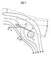
- FIG. 1 shows a device for generating vortices with a flow around of a flow medium S profile 1, for example, in an in FIG. 1 Can not be located flow channel.
- the flow direction of the flow medium S is indicated by the arrows 2 in the manner of streamlines.
- the profile 1 is characterized by a in FIG. 1 not shown outer drive movable, wherein the movement is generally composed of a displacement of the profile 1 by a distance x and a rotation of the profile 1 by an angle ⁇ . The movement takes place periodically with an angular frequency ⁇ .
- the forming vortices can be described relatively realistically with the help of the "Finite eddy model".
- vortexes forming at the trailing edge 4 of the profile 1 are not described as ideal vortexes but as vortexes with sharply defined radius and rigidly rotating core.
- FIG. 1 is such, so-called “Finite eddy vertebrae” 6 shown.
- the finite edge vortex 6 is filled immediately after its formation at the trailing edge 4 of the flow-around profile 1 by flowing to its center flow medium S up to its radius a and set in rotation.
- the relatively simple "finite eddy model" allows in contrast to the classical wing theory, the description of the flow around an accelerated moving profile 1.
- An accelerated moving profile 1 in contrast to a rigid on a much lower dynamic resistance.
- a moving profile 1 causes a considerably lower pressure loss within the flow medium S than a rigid one. It can thus be used, for example, for the efficient transporting or mixing of flow media S, wherein due to the low dynamic resistance of the profile 1, a comparatively high throughput of flow medium is achieved with a simultaneous low pressure loss.
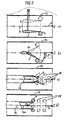
- FIG. 2 shows various possibilities of the periodic movement of the profile 1 relative to the flow medium S.
- the flow medium S flows in the direction indicated by the arrow 2 a flow channel 12.
- a finite edge vortex 6 can be produced in the flow medium S by periodically displacing a profile 1 perpendicular to the flow direction by a distance x according to the invention, that is to say carrying out a pure translational movement.
- FIG. 2b shows another possibility of periodic movement of the profile 1, in which the profile 1 performs a pure rotational movement about an axis of rotation 14 perpendicular to the flow direction by an angle ⁇ .
- the use of combinations of translational and rotational movements may be advantageous.
- several profiles 1 are used to generate vertebrae. With a constellation like in 2c in which a pair of profiles 1 at the output of a further flow channel arranged in the flow channel 12 oscillates 16 in push-pull or common mode, for example two flow media flowing in the flow channel 12 and subsequently flow channel 16 efficiently mix and / or transport.
- a further flow channel 16 is arranged here within a flow channel 12, which is flowed through by a flow medium S. However, flows through the flow medium S of the further flow channel 16 with a periodic variation of its mass flow m. At the outlet 22 of the further flow channel, a pair of finite edge vertebrae 6 forms in each period, which separates off after the adhesion phase and forms a wake 18 in the flow channel 12.
- the profiles 1 should follow certain rules in their shape and dimensioning.
- the profiles 1 should have a very long but sharp trailing edge 4, so that the maximum flow velocity at the trailing edge 4 is as high as possible and the resulting finite edge vortex 6 has a comparatively small radius.
- a harmonic oscillation shape of the profile 1 is not desirable in each case, in order to achieve a long adhesion phase of the finite edge vortex 6 and a high propulsion.
- the position of the rotation axis 14 in a rotation and the general shape of the profile 1 must be optimized so that with minimal external drive and low pressure drop an optimal energy transfer between profile 1 and flow medium S.
- FIG. 3 shows a route for transporting a flow medium, comprising a device for generating finite eddy 6.
- a plurality of, for example three, profiles 1 are arranged in a flow channel 12, which perform a periodic movement in common mode.
- the periodic movement may consist in a rotation about the angle ⁇ about a rotation axis 14 or also in a combination of the rotation with a periodic displacement of the profile 1.
- profiles 1 arise in each period two finite eddy 6.
- the energy transferred from the profiles 1 by the vortex formation on the flow medium S energy is used for the transport of the flow medium S through the flow channel 12. If the profiles 1 perform a pure rotational movement, they can be moved by the in FIG. 3b be shown external drive driven.
- the profiles 1 are mounted in the region of their trailing edge 4 on a connecting rod 23 which is connected via a hinge lever 24 with a crank drive 26. In the operating case of the vortex generator, the crank drive 26 moves the connecting rod 23 up and down and thus drives the rotation of the profiles 1 about their respective axis of rotation 14.
- the drive device shown comprises a connecting rod 23 to which the one or more profiles 1 are mounted in its rear region and a further connecting rod 30 which connects the profiles 1 in their front region with each other.
- Both the connecting rod 23 and the further connecting rod 30 perform in the operating case of the device a periodic movement in the upward and downward direction, which is effected by an electromagnetic drive 27 and via a further electromagnetic drive 28.
- the electromagnetic work Drive 27 and the further electromagnetic drive 28 is not in phase. Instead, the electromagnetic drive 27 may have a phase advance of 90 degrees relative to the further electromagnetic drive 28.
- the profiles 12 thus perform a combination of a translational movement about the distance x and a rotational movement by the angle ⁇ within the flow channel 12.
- the flow medium S can be particularly efficiently transported through a flow channel 12. Namely, as calculations have shown in the context of the "finite edge vortex model", the periodic movement of the profiles 1 ensures that energy is transferred from the profiles 1 to the flow medium S in a particularly efficient manner. In particular, the throughput of flow medium S related to the pressure loss through the flow channel 12 can be maximized in this way.
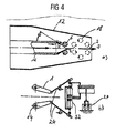
- FIG. 4a shows an alternative route for efficiently transporting a flow medium S.
- a further flow channel 16 is arranged concentrically, for example, at the outlet of a pair of profiles 1 is arranged, each performing periodic rotational movements. They swing in push-pull, ie with a phase shift of 180 degrees and generate at their trailing edge 4 per period two finite edge vortices 6, which detach after their adhesion phase of the trailing edge 4 and generate a wake 18 in the flow channel.
- the profiles 1 flow medium side in FIG. 4 not shown vortex killers downstream.
- the drive comprises an electromagnetic drive 27, which drives a hydraulically operating working cylinder 32, and two articulated levers 24, which are attached to the profiles 1 and bring about their caused by the working cylinder 32 movement of the profiles 1 about their respective axis of rotation 14.
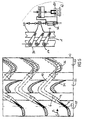
- FIG. 5 represents the principle of the application of active vortex generators to increase the efficiency of a lattice flow.
- an axial lattice in FIG. 5a represented by a cylindrical, unrolled in the plane section upstream of a number of active vortex generators.
- FIG. 5a shows a number of vanes 34 comprising Leitschaufelsch 33 of a gas turbine, the flow medium side of a number of blades 36 comprising blade row 35 is connected downstream.
- the guide blade row 34 and the blade row 35 are arranged in a flow channel, not shown, which is flowed through by the flow medium S in the direction indicated by the arrow 2 direction.
- the guide vane row 34 is preceded by a vortex generator row 38 on the flow medium side, which comprises a number of profiles 1.
- the profiles 1 are designed so that they are rotated by an outer drive about their respective axis of rotation 14.
- each profile 1 generates at its trailing edge 4 two finite edge vortices 6, which detach after the adhesion phase and move on the path indicated by the arrow 40 through the flow channel.
- the finite eddies 6 move through the profiles transferred to them from the profiles 1 on their path around the vanes 34 and meet the guide vanes 34 flow medium side downstream blades 36 to which they give their energy.
- the on this Flow pulses generated in one way increase the efficiency of the lattice flow, inter alia, by using the not yet fully understood so-called "clocking effect", an effect that is based on the aerodynamic interaction of different lattices and which comes into play when the lattice defines a well-defined one Position each other.
- the clocking effect already used in the positioning of the guide vanes 34 relative to the moving blades 36 is further enhanced by the production of continuous flow pulses in the duration and frequency for moving the moving blades 36 through the profiles 1. It increases the efficiency of the lattice flow measurably and can therefore contribute to increasing the efficiency of, for example, a gas turbine and thus to reducing their emissions.
- FIG. 5b is a possible driver for the in FIG. 5a shown profiles 1 shown.
- the profiles 1 are mounted in the region of their trailing edge 4 on a common connecting rod 23 and mounted rotatably in their front region on a further connecting rod 30 about their respective axis of rotation 14.
- the electromagnetic drive 27 moves the connecting rod 23 upwards or downwards via the hydraulically operating working cylinder 32. The result is an in-phase rotation of the profiles 1 about their respective axis of rotation 14th
- FIG. 6 shows an arrangement in which generated by the profiles 1 finite edge vortex 6 can be used to cool thermally stressed components.
- a flow channel 12 for example a gas turbine
- the connecting rod 23 can be moved by an external drive in the direction indicated by the arrow 42 periodically upward and then down again.
- the drive of the connecting rod 23 may be mechanical as in 6a or alternatively, electromagnetically as in FIG. 6b respectively.
- the profiles 1 perform in the case of operation due to the external drive a translational movement about the distance x within the flow channel 12 and thereby characterize the flow medium S on the velocity profile p.
- the resulting at the moving trailing edges 4 of the profiles 1 and 5 detached from the profiles fin edged vertebrae 6 in turn shape the velocity profile p periodic speed fluctuations, which increase the heat exchange across the flow direction significantly and thus contribute to the desired improvement in the cooling of the wall 44.
- the improvement in the cooling effect of the flow is due to the upstream displacement of the laminar-turbulent transition point of the flow through the use of the vortex generator. This significantly increases the heat transfer coefficient and improves the cooling effect.
- flow medium S can be saved or, with the same expenditure of flow medium S, a power and efficiency increase of the gas turbine can be achieved.
- the increased through the use of a vortex generator mass transfer transverse to the flow direction can also be used for mixing of flow media together.
- a profile 1 which is moved periodically by an external drive.
- the drive takes place as in FIG. 7b represented, mechanically via a crank loop.
- the periodically moving profile 1 generates during each period two finite edge vortices 4, which arise at its trailing edge 4 and detach after the adhesion phase.
- the on this Way selectively generated turbulence ensured efficient mixing of the flow medium S, which may for example consist of several components such as air and fuel gas or light fuel oil and water to be mixed together.
- the profile 1 for generating vortices can flow medium side in FIG. 7 not shown profile for the destruction of vortices downstream, if a turbulent flow in the course is not desired.
Landscapes
- Engineering & Computer Science (AREA)
- Physics & Mathematics (AREA)
- Theoretical Computer Science (AREA)
- Chemical & Material Sciences (AREA)
- General Engineering & Computer Science (AREA)
- Mechanical Engineering (AREA)
- Evolutionary Computation (AREA)
- Geometry (AREA)
- General Physics & Mathematics (AREA)
- Computer Hardware Design (AREA)
- Fluid Mechanics (AREA)
- Dispersion Chemistry (AREA)
- Chemical Kinetics & Catalysis (AREA)
- Structures Of Non-Positive Displacement Pumps (AREA)
- Turbine Rotor Nozzle Sealing (AREA)
Claims (14)
- Dispositif de production et/ou de suppression de tourbillons dans un fluide (S) en écoulement, qui comprend un canal (12) d'écoulement et un ou plusieurs profilés (1) disposés dans le canal (12) d'écoulement et prévus pour être contournés par le fluide (S) en écoulement, un entraînement extérieur appartenant au dispositif et conçu pour la production d'un mouvement d'oscillation périodique du profilé (1) respectif par rapport au fluide (S) en écoulement ayant une pulsation ω étant associé au profilé ou à chaque profilé (1),
caractérisé en ce que
le mouvement périodique d'oscillation est constitué d'un déplacement en translation pure des profilés (1) perpendiculairement à une direction d'écoulement du fluide (S) en écoulement. - Dispositif suivant la revendication 1, dans lequel la forme et la dimension des profilés (1) sont choisies de façon à ce que, en fonctionnement, le quotient de la vitesse d'écoulement, en moyenne sur une période d'oscillation, du profilé (1), rapportée à la section transversale médiane du profilé (1), à la vitesse maximum d'écoulement sur le bord (4) arrière du profilé ait une valeur prescrite.
- Dispositif suivant l'une des revendication 1 à 2, en aval duquel peut être monté du côté du fluide en écoulement un dispositif de suppression de tourbillons.
- Voie de transport d'un fluide (S) en écoulement, comprenant un dispositif suivant l'une des revendications 1 à 3, qui comporte un certain nombre de profilés (1) qui exécutent un mouvement périodique d'oscillation de même pulsation ω et de même phase.
- Grille axiale de passage d'un fluide (S) en écoulement, comprenant un dispositif suivant l'une des revendications 1 à 3, qui est monté en amont du côté fluide en écoulement de la grille axiale et qui comprend un certain nombre de profilés (1) qui exécutent un mouvement périodique d'oscillation de même pulsation ω et de même phase.
- Dispositif de refroidissement pour refroidir des éléments sollicités thermiquement, qui comprend un canal (12) d'écoulement, un courant de refroidissement passant dans le canal (12) d'écoulement ainsi qu'un dispositif suivant l'une des revendications 1 à 3 disposé dans le canal (12) d'écoulement.
- Voie de mélange pour mélanger un ou plusieurs fluides (S) en écoulement entre eux, qui comprend un canal (12) d'écoulement, dans lequel les fluides (S) en écoulement peuvent passer, ainsi qu'un dispositif suivant l'une des revendications 1 à 3.
- Turbine à gaz ayant un dispositif suivant l'une des revendications 1 à 7.
- Procédé de production de tourbillons dans un fluide (S) en écoulement par un profilé (1) ou par un certain nombre de profilés (1) disposés dans un canal (12) d'écoulement et prévus pour être contournés par le fluide en écoulement, dans lequel le profilé (1) ou les profilés (1) sont mis en oscillation périodiquement à la pulsation w par un entraînement extérieur,
caractérisé en ce que
pour transmettre de l'énergie au fluide en écoulement, le quotient de la vitesse d'écoulement, en moyenne sur une période d'oscillation, du profilé (1), rapportée à la section transversale médiane du profilé (1), à la vitesse d'écoulement maximum sur le bord (4) arrière du profilé (1) est compris entre 0,2 et 0,5 et/ou pour la transmission d'énergie au profilé (1) le quotient est supérieur à 0,5. - Procédé suivant la revendication 9,
dans lequel on supprime à nouveau, en tout ou en partie, les tourbillons produits en aval de la position dans le canal (12) d'écoulement où ils ont été produits. - Procédé suivant l'une des revendications 9 à 10,
que l'on utilise pour le transport d'un fluide (S) en écoulement dans un canal (12) d'écoulement. - Procédé suivant l'une des revendications 9 à 11,
que l'on utilise pour augmenter l'efficacité d'un écoulement du fluide (S) en écoulement à travers une grille disposée dans le canal (12) d'écoulement. - Procédé suivant l'une des revendications 9 à 11,
que l'on utilise pour le refroidissement par un fluide (S) en écoulement d'éléments sollicités thermiquement. - Procédé suivant l'une des revendications 9 à 11,
que l'on utilise pour le mélange d'un ou de plusieurs fluides (S) en écoulement dans un canal (12) d'écoulement.
Applications Claiming Priority (3)
| Application Number | Priority Date | Filing Date | Title |
|---|---|---|---|
| DE10237341A DE10237341A1 (de) | 2002-08-14 | 2002-08-14 | Modell, Berechnung und Anwendung periodisch erzeugter Kantenwirbel im Turbomaschinenbau |
| DE10237341 | 2002-08-14 | ||
| PCT/DE2003/002721 WO2004020841A1 (fr) | 2002-08-14 | 2003-08-12 | Dispositif pour produire des tourbillons et procede pour faire fonctionner ledit dispositif |
Publications (2)
| Publication Number | Publication Date |
|---|---|
| EP1529169A1 EP1529169A1 (fr) | 2005-05-11 |
| EP1529169B1 true EP1529169B1 (fr) | 2009-07-01 |
Family
ID=30775289
Family Applications (1)
| Application Number | Title | Priority Date | Filing Date |
|---|---|---|---|
| EP03790717A Expired - Lifetime EP1529169B1 (fr) | 2002-08-14 | 2003-08-12 | Dispositif pour produire des tourbillons et procede pour faire fonctionner ledit dispositif |
Country Status (6)
| Country | Link |
|---|---|
| US (1) | US7431244B2 (fr) |
| EP (1) | EP1529169B1 (fr) |
| CN (1) | CN1325807C (fr) |
| DE (2) | DE10237341A1 (fr) |
| ES (1) | ES2326219T3 (fr) |
| WO (1) | WO2004020841A1 (fr) |
Families Citing this family (10)
| Publication number | Priority date | Publication date | Assignee | Title |
|---|---|---|---|---|
| DE10341960B4 (de) * | 2003-09-11 | 2008-02-07 | Glunz Ag | Mischverfahren und statischer Mischer, insbesondere zur Beleimung von lignocellulosehaltigen Fasern mit einem Bindemittel |
| EP1724440B1 (fr) * | 2005-05-10 | 2008-08-06 | MTU Aero Engines GmbH | Procédé pour optimiser l'écoulement dans des turbomachines multi-étages |
| EP2025868A1 (fr) * | 2007-08-10 | 2009-02-18 | Siemens Aktiengesellschaft | Aube de turbine avec turbulateur à l'entrée d'air de refroidissement |
| FR2925106B1 (fr) * | 2007-12-14 | 2010-01-22 | Snecma | Procede de conception d'une turbine multi-etages de turbomachine |
| EP2577071B1 (fr) | 2010-06-01 | 2017-12-20 | Esg Mbh | Canal à surface de guidage d'écoulement |
| CN103062138A (zh) * | 2013-01-15 | 2013-04-24 | 上海大学 | 一种流动分离控制装置 |
| CA2899238A1 (fr) * | 2013-01-25 | 2014-07-31 | Peter Ireland | Ameliorations en termes d'efficacite energetique pour une turbomachine |
| CN109441554B (zh) * | 2018-10-29 | 2021-01-19 | 中国民航大学 | 一种适用于航空发动机的涡轮叶片 |
| WO2020114763A1 (fr) * | 2018-12-06 | 2020-06-11 | Asml Netherlands B.V. | Restriction de débit, ensemble de restriction de débit et appareil lithographique |
| CN109859311B (zh) * | 2019-01-29 | 2021-05-18 | 河海大学 | 基于Liutex-Omega涡识别理论的模拟方法 |
Family Cites Families (21)
| Publication number | Priority date | Publication date | Assignee | Title |
|---|---|---|---|---|
| DE215155C (fr) | ||||
| DE900526C (de) | 1951-06-16 | 1953-12-28 | Walter Ernst | Foerderklappe fuer Fluessigkeiten |
| US2813708A (en) * | 1951-10-08 | 1957-11-19 | Frey Kurt Paul Hermann | Devices to improve flow pattern and heat transfer in heat exchange zones of brick-lined furnaces |
| US2740596A (en) * | 1953-08-19 | 1956-04-03 | United Aircraft Corp | Vortex generator |
| GB763359A (en) * | 1954-01-21 | 1956-12-12 | Lucas Industries Ltd | Combustion chambers for jet propulsion engines, gas turbines or other apparatus |
| US2878831A (en) * | 1957-02-04 | 1959-03-24 | Farnham Rex Couvelas | Fluid control means |
| US3241771A (en) * | 1963-09-18 | 1966-03-22 | Gen Electric | Thrust deflector and reverser |
| US3475108A (en) * | 1968-02-14 | 1969-10-28 | Siemens Ag | Blade structure for turbines |
| US3986787A (en) * | 1974-05-07 | 1976-10-19 | Mouton Jr William J | River turbine |
| US4058141A (en) * | 1975-08-20 | 1977-11-15 | The United States Of America As Represented By The Secretary Of The Air Force | Supersonic flow diffuser with energy redistribution |
| AT387955B (de) * | 1981-01-13 | 1989-04-10 | Sneek Landustrie | Vorrichtung zum antreiben einer fluessigkeit in einem kanal |
| US4667900A (en) * | 1981-03-05 | 1987-05-26 | Kyusik Kim | Ram constriction vane diffuser for jet engine |
| FR2528500A1 (fr) | 1982-06-11 | 1983-12-16 | Agronomique Inst Nat Rech | Ventilateur silencieux et ventilo-convecteur muni d'un tel ventilateur |
| DD215155A1 (de) * | 1983-05-05 | 1984-10-31 | Zittau Ing Hochschule | Turbulator und verfahren zur erhoehung des waermeuebergangs |
| US4844382A (en) * | 1983-10-19 | 1989-07-04 | Raisbeck Engineering, Inc. | Dual turning vane air inlet assembly |
| DE3343296A1 (de) * | 1983-11-30 | 1985-06-05 | Theod. Mahr Söhne GmbH, 5100 Aachen | Einrichtung zur regulierung des volumenstroms in einem stroemungskanal |
| US5525269A (en) * | 1985-03-22 | 1996-06-11 | Philadelphia Gear Corporation | Impeller tiplets for improving gas to liquid mass transfer efficiency in a draft tube submerged turbine mixer/aerator |
| JPH03160200A (ja) | 1989-11-15 | 1991-07-10 | Kenji Oe | 送風器 |
| US5302092A (en) | 1991-06-07 | 1994-04-12 | Daikin Industries, Ltd. | Fluid transferring apparatus imitating flapping movement of bees |
| US5486091A (en) * | 1994-04-19 | 1996-01-23 | United Technologies Corporation | Gas turbine airfoil clocking |
| US7108569B2 (en) * | 2003-03-19 | 2006-09-19 | Cornell Donald E | Axial flow pump or marine propulsion device |
-
2002
- 2002-08-14 DE DE10237341A patent/DE10237341A1/de not_active Withdrawn
-
2003
- 2003-08-12 EP EP03790717A patent/EP1529169B1/fr not_active Expired - Lifetime
- 2003-08-12 US US10/523,512 patent/US7431244B2/en not_active Expired - Fee Related
- 2003-08-12 WO PCT/DE2003/002721 patent/WO2004020841A1/fr not_active Ceased
- 2003-08-12 ES ES03790717T patent/ES2326219T3/es not_active Expired - Lifetime
- 2003-08-12 CN CNB038173182A patent/CN1325807C/zh not_active Expired - Fee Related
- 2003-08-12 DE DE50311668T patent/DE50311668D1/de not_active Expired - Lifetime
Also Published As
| Publication number | Publication date |
|---|---|
| WO2004020841A1 (fr) | 2004-03-11 |
| US7431244B2 (en) | 2008-10-07 |
| DE50311668D1 (de) | 2009-08-13 |
| CN1668853A (zh) | 2005-09-14 |
| ES2326219T3 (es) | 2009-10-05 |
| US20060102799A1 (en) | 2006-05-18 |
| CN1325807C (zh) | 2007-07-11 |
| EP1529169A1 (fr) | 2005-05-11 |
| DE10237341A1 (de) | 2004-02-26 |
Similar Documents
| Publication | Publication Date | Title |
|---|---|---|
| DE60004492T2 (de) | Vibrationsangetriebener akustischer strahl, der die ablösung der grenzschicht kontrolliert | |
| DE69729106T2 (de) | Energiegewinnung aus strömenden fluiden | |
| DE2523030C2 (de) | Anordnung zur Nutzung der Energie eines Flüssigkeitsstromes | |
| DE1934246A1 (de) | Grenzschichtenkontrolle fuer Fliessabtrennung und Waermeaustausch | |
| DE102008024463B4 (de) | Flugzeugantriebssystem | |
| EP3329120B1 (fr) | Pale d'éolienne | |
| DE1476796B2 (de) | Aus einem hochfesten Material integral hergestelltes Bauteil einer Gasturbinenanlage | |
| DE202004021476U1 (de) | Apparat zur Reinigung eines Turbofan-Gasturbinentriebwerks | |
| DE19815519A1 (de) | Rotorblatt für eine Windkraftanlage | |
| CH698336A2 (de) | Turbinenschaufel mit einem gekühlten Deckblatt. | |
| WO2004020841A1 (fr) | Dispositif pour produire des tourbillons et procede pour faire fonctionner ledit dispositif | |
| DE2953300A1 (en) | Exhaust pipe of turbine | |
| CH619039A5 (fr) | ||
| EP1557533B1 (fr) | Refroidissement d'une aube de turbine avec faux-plancher entre l'aube et son extrémité | |
| EP2310268A1 (fr) | Avion pourvu d'au moins deux systèmes de propulsion à hélice espacés dans le sens de l'envergure des ailes | |
| DE102011122140A1 (de) | Delta-Wirbelstromgeneratoren | |
| DE2729873A1 (de) | Vorrichtung zur umwandlung von energie einer stroemung oder der rieselnden bewegung eines rieselfaehigen mediums in eine mechanische bewegung | |
| EP1964774A2 (fr) | Aéronef doté d'un cylindre rotatif destiné à la production de sustentation et/ou de poussée | |
| DE69126542T2 (de) | Rückgewinnunganlage der stosswelleenergie eines überschallflugzeuges | |
| EP2223853A1 (fr) | Surface à écoulement dynamique dotée d'une turbine entraînée par un écoulement induit à l'aide de la surface d'écoulement | |
| EP3399183A1 (fr) | Pale de rotor d'une éolienne | |
| DE3303898C2 (de) | Verfahren zur Windenergienutzung, sowie dazugehörige Vorrichtung | |
| DE4320180A1 (de) | Läufereinheit für eine Axialströmungsmaschine | |
| DE102017106774B4 (de) | Hubschrauber mit einem Rotorblatt und einer Wärmequelle | |
| DE102019126123A1 (de) | Wärmetauscher eines Gasturbinentriebwerkes eines Flugzeuges |
Legal Events
| Date | Code | Title | Description |
|---|---|---|---|
| PUAI | Public reference made under article 153(3) epc to a published international application that has entered the european phase |
Free format text: ORIGINAL CODE: 0009012 |
|
| 17P | Request for examination filed |
Effective date: 20041201 |
|
| AK | Designated contracting states |
Kind code of ref document: A1 Designated state(s): AT BE BG CH CY CZ DE DK EE ES FI FR GB GR HU IE IT LI LU MC NL PT RO SE SI SK TR |
|
| RBV | Designated contracting states (corrected) |
Designated state(s): CH DE ES GB IT LI |
|
| 17Q | First examination report despatched |
Effective date: 20070711 |
|
| GRAP | Despatch of communication of intention to grant a patent |
Free format text: ORIGINAL CODE: EPIDOSNIGR1 |
|
| GRAS | Grant fee paid |
Free format text: ORIGINAL CODE: EPIDOSNIGR3 |
|
| GRAA | (expected) grant |
Free format text: ORIGINAL CODE: 0009210 |
|
| AK | Designated contracting states |
Kind code of ref document: B1 Designated state(s): CH DE ES GB IT LI |
|
| REG | Reference to a national code |
Ref country code: GB Ref legal event code: FG4D Free format text: NOT ENGLISH |
|
| REG | Reference to a national code |
Ref country code: CH Ref legal event code: NV Representative=s name: SIEMENS SCHWEIZ AG Ref country code: CH Ref legal event code: EP |
|
| REF | Corresponds to: |
Ref document number: 50311668 Country of ref document: DE Date of ref document: 20090813 Kind code of ref document: P |
|
| REG | Reference to a national code |
Ref country code: ES Ref legal event code: FG2A Ref document number: 2326219 Country of ref document: ES Kind code of ref document: T3 |
|
| PLBE | No opposition filed within time limit |
Free format text: ORIGINAL CODE: 0009261 |
|
| STAA | Information on the status of an ep patent application or granted ep patent |
Free format text: STATUS: NO OPPOSITION FILED WITHIN TIME LIMIT |
|
| 26N | No opposition filed |
Effective date: 20100406 |
|
| PGFP | Annual fee paid to national office [announced via postgrant information from national office to epo] |
Ref country code: ES Payment date: 20100907 Year of fee payment: 8 |
|
| PGFP | Annual fee paid to national office [announced via postgrant information from national office to epo] |
Ref country code: IT Payment date: 20100825 Year of fee payment: 8 |
|
| PGFP | Annual fee paid to national office [announced via postgrant information from national office to epo] |
Ref country code: GB Payment date: 20100812 Year of fee payment: 8 |
|
| PGFP | Annual fee paid to national office [announced via postgrant information from national office to epo] |
Ref country code: CH Payment date: 20101109 Year of fee payment: 8 Ref country code: DE Payment date: 20101018 Year of fee payment: 8 |
|
| REG | Reference to a national code |
Ref country code: CH Ref legal event code: PL |
|
| GBPC | Gb: european patent ceased through non-payment of renewal fee |
Effective date: 20110812 |
|
| PG25 | Lapsed in a contracting state [announced via postgrant information from national office to epo] |
Ref country code: CH Free format text: LAPSE BECAUSE OF NON-PAYMENT OF DUE FEES Effective date: 20110831 Ref country code: LI Free format text: LAPSE BECAUSE OF NON-PAYMENT OF DUE FEES Effective date: 20110831 |
|
| PG25 | Lapsed in a contracting state [announced via postgrant information from national office to epo] |
Ref country code: IT Free format text: LAPSE BECAUSE OF NON-PAYMENT OF DUE FEES Effective date: 20110812 |
|
| REG | Reference to a national code |
Ref country code: DE Ref legal event code: R119 Ref document number: 50311668 Country of ref document: DE Effective date: 20120301 |
|
| PG25 | Lapsed in a contracting state [announced via postgrant information from national office to epo] |
Ref country code: GB Free format text: LAPSE BECAUSE OF NON-PAYMENT OF DUE FEES Effective date: 20110812 |
|
| REG | Reference to a national code |
Ref country code: ES Ref legal event code: FD2A Effective date: 20130606 |
|
| PG25 | Lapsed in a contracting state [announced via postgrant information from national office to epo] |
Ref country code: DE Free format text: LAPSE BECAUSE OF NON-PAYMENT OF DUE FEES Effective date: 20120301 |
|
| PG25 | Lapsed in a contracting state [announced via postgrant information from national office to epo] |
Ref country code: ES Free format text: LAPSE BECAUSE OF NON-PAYMENT OF DUE FEES Effective date: 20110813 |