EP1528425A1 - Assemblage et appareillage pour la transformation de faisceaux optiques - Google Patents
Assemblage et appareillage pour la transformation de faisceaux optiques Download PDFInfo
- Publication number
- EP1528425A1 EP1528425A1 EP03024780A EP03024780A EP1528425A1 EP 1528425 A1 EP1528425 A1 EP 1528425A1 EP 03024780 A EP03024780 A EP 03024780A EP 03024780 A EP03024780 A EP 03024780A EP 1528425 A1 EP1528425 A1 EP 1528425A1
- Authority
- EP
- European Patent Office
- Prior art keywords
- light beam
- cylindrical lenses
- divergence
- optical beam
- transformation
- Prior art date
- Legal status (The legal status is an assumption and is not a legal conclusion. Google has not performed a legal analysis and makes no representation as to the accuracy of the status listed.)
- Granted
Links
Images


Classifications
-
- G—PHYSICS
- G02—OPTICS
- G02B—OPTICAL ELEMENTS, SYSTEMS OR APPARATUS
- G02B19/00—Condensers, e.g. light collectors or similar non-imaging optics
- G02B19/0033—Condensers, e.g. light collectors or similar non-imaging optics characterised by the use
- G02B19/0047—Condensers, e.g. light collectors or similar non-imaging optics characterised by the use for use with a light source
- G02B19/0061—Condensers, e.g. light collectors or similar non-imaging optics characterised by the use for use with a light source the light source comprising a LED
- G02B19/0066—Condensers, e.g. light collectors or similar non-imaging optics characterised by the use for use with a light source the light source comprising a LED in the form of an LED array
-
- G—PHYSICS
- G02—OPTICS
- G02B—OPTICAL ELEMENTS, SYSTEMS OR APPARATUS
- G02B19/00—Condensers, e.g. light collectors or similar non-imaging optics
- G02B19/0004—Condensers, e.g. light collectors or similar non-imaging optics characterised by the optical means employed
- G02B19/0009—Condensers, e.g. light collectors or similar non-imaging optics characterised by the optical means employed having refractive surfaces only
- G02B19/0014—Condensers, e.g. light collectors or similar non-imaging optics characterised by the optical means employed having refractive surfaces only at least one surface having optical power
-
- G—PHYSICS
- G02—OPTICS
- G02B—OPTICAL ELEMENTS, SYSTEMS OR APPARATUS
- G02B27/00—Optical systems or apparatus not provided for by any of the groups G02B1/00 - G02B26/00, G02B30/00
-
- G—PHYSICS
- G02—OPTICS
- G02B—OPTICAL ELEMENTS, SYSTEMS OR APPARATUS
- G02B27/00—Optical systems or apparatus not provided for by any of the groups G02B1/00 - G02B26/00, G02B30/00
- G02B27/09—Beam shaping, e.g. changing the cross-sectional area, not otherwise provided for
-
- G—PHYSICS
- G02—OPTICS
- G02B—OPTICAL ELEMENTS, SYSTEMS OR APPARATUS
- G02B27/00—Optical systems or apparatus not provided for by any of the groups G02B1/00 - G02B26/00, G02B30/00
- G02B27/09—Beam shaping, e.g. changing the cross-sectional area, not otherwise provided for
- G02B27/0938—Using specific optical elements
- G02B27/095—Refractive optical elements
- G02B27/0955—Lenses
- G02B27/0961—Lens arrays
-
- G—PHYSICS
- G02—OPTICS
- G02B—OPTICAL ELEMENTS, SYSTEMS OR APPARATUS
- G02B27/00—Optical systems or apparatus not provided for by any of the groups G02B1/00 - G02B26/00, G02B30/00
- G02B27/09—Beam shaping, e.g. changing the cross-sectional area, not otherwise provided for
- G02B27/0938—Using specific optical elements
- G02B27/095—Refractive optical elements
- G02B27/0955—Lenses
- G02B27/0966—Cylindrical lenses
-
- G—PHYSICS
- G02—OPTICS
- G02B—OPTICAL ELEMENTS, SYSTEMS OR APPARATUS
- G02B6/00—Light guides; Structural details of arrangements comprising light guides and other optical elements, e.g. couplings
- G02B6/24—Coupling light guides
- G02B6/42—Coupling light guides with opto-electronic elements
- G02B6/4201—Packages, e.g. shape, construction, internal or external details
- G02B6/4204—Packages, e.g. shape, construction, internal or external details the coupling comprising intermediate optical elements, e.g. lenses, holograms
-
- G—PHYSICS
- G02—OPTICS
- G02B—OPTICAL ELEMENTS, SYSTEMS OR APPARATUS
- G02B6/00—Light guides; Structural details of arrangements comprising light guides and other optical elements, e.g. couplings
- G02B6/24—Coupling light guides
- G02B6/42—Coupling light guides with opto-electronic elements
- G02B6/4201—Packages, e.g. shape, construction, internal or external details
- G02B6/4249—Packages, e.g. shape, construction, internal or external details comprising arrays of active devices and fibres
-
- H—ELECTRICITY
- H01—ELECTRIC ELEMENTS
- H01S—DEVICES USING THE PROCESS OF LIGHT AMPLIFICATION BY STIMULATED EMISSION OF RADIATION [LASER] TO AMPLIFY OR GENERATE LIGHT; DEVICES USING STIMULATED EMISSION OF ELECTROMAGNETIC RADIATION IN WAVE RANGES OTHER THAN OPTICAL
- H01S5/00—Semiconductor lasers
- H01S5/40—Arrangement of two or more semiconductor lasers, not provided for in groups H01S5/02 - H01S5/30
- H01S5/4012—Beam combining, e.g. by the use of fibres, gratings, polarisers, prisms
-
- H—ELECTRICITY
- H01—ELECTRIC ELEMENTS
- H01S—DEVICES USING THE PROCESS OF LIGHT AMPLIFICATION BY STIMULATED EMISSION OF RADIATION [LASER] TO AMPLIFY OR GENERATE LIGHT; DEVICES USING STIMULATED EMISSION OF ELECTROMAGNETIC RADIATION IN WAVE RANGES OTHER THAN OPTICAL
- H01S5/00—Semiconductor lasers
- H01S5/40—Arrangement of two or more semiconductor lasers, not provided for in groups H01S5/02 - H01S5/30
- H01S5/4025—Array arrangements, e.g. constituted by discrete laser diodes or laser bar
Definitions
- the present invention relates to an arrangement for optical Beam transformation comprising at least one light source, the can emit at least one light beam, the at least a ray of light in a first direction has a greater divergence than in a second direction perpendicular thereto, a Collimating agent that detects the divergence of at least one Light beam in the first direction can at least reduce one Apparatus for optical beam transformation, in Propagation direction of the at least one light beam behind the Collimating means is arranged, wherein the device such is designed that the divergence of the device passing through at least one light beam in the first Direction with the divergence in the second direction perpendicular thereto is exchanged.
- the present invention relates to a Apparatus for optical beam transformation with at least one Entry and at least one exit surface, wherein the device is designed such that the divergence of a through the device passing light beam in the first direction with the Divergence is exchanged in the second direction perpendicular thereto.
- the device described therein comprises, for example, a substrate made of a transparent material that has an entrance surface and a Has exit surface. Both the entrance area and the Exit surface are formed substantially rectangular and elongated. The longitudinal extent of the entrance surface and the Exit surface substantially corresponds to the second direction. If a laser diode bar is used as the light source, this second direction corresponds to the direction in which individual emitters the laser diode bar side by side and spaced from each other are arranged. This direction of lesser divergence becomes slow axis called.
- the vertical first direction is the direction greater divergence in semiconductor laser diode bars near-axis is called.
- This also has its own Reason in that in terms of the direction of propagation vertical direction behind the device a picture of the single emitter, for example, as a laser diode bar whereas this is done with regard to the other to the direction of propagation and to the above-mentioned direction is not the case. Furthermore, the expansion of the beam during the Passing through the device cause the individual Partial beams at least partially overlap, leaving alone For this reason, no clean focus of all Partial beams on a common focus area is possible.
- the problem underlying the present invention is the Creation of an arrangement and a device of the beginning mentioned type, the more focusable light beam after Allow passage through the device.
- the device for optical beam transformation is designed such that the cross-sectional area of the at least one Light beam in the apparatus for optical beam transformation is reduced.
- the reduction of the at least one Light beam in the device can be effectively prevented that a plurality of light rays passing through the device while passing through the device or just behind it overlap with each other.
- the reduction can be for example in two mutually perpendicular and the propagation direction vertical directions be the same strength, especially about one Factor two correspond.
- the device for optical beam transformation is designed in such a way that she is an image of at least one of her too transforming light beam with respect to two to each other and to the propagation direction of the light beam perpendicular directions in can create a plane.
- she is an image of at least one of her too transforming light beam with respect to two to each other and to the propagation direction of the light beam perpendicular directions in can create a plane.
- claim 3 or claim 7 can be provided be that the plane in which the image of the transforming Light beam can be generated, one to the propagation direction vertical plane is.
- the arrangement in Propagation direction of the at least one light beam behind the Apparatus for optical beam transformation collimating means and / or focusing means for collimation and / or focusing the at least one light beam comprises.
- the at least one light source as a semiconductor laser device is designed in particular as a semiconductor laser diode bar.
- the Cylindrical lenses with the second direction an angle of + 45 ° and / or - 45 °.
- the at least one entry and / or the at least one Exit surface of the device is a substantially elongated, preferably rectangular in shape, wherein the longitudinal direction of Entry and / or the exit surface substantially the second Direction corresponds.
- the Device comprises two parts, each having an entrance surface and have an exit surface.
- the cylindrical lenses on two surfaces of the parts perpendicular to the cylindrical lenses on two other surfaces of the parts are aligned.
- the orientation of cylindrical lenses on some of the surfaces perpendicular to the Cylindrical lenses on other of the surfaces can be achieved that the at least one passing through the device Light beam with respect to two mutually perpendicular directions is influenced by the device.
- At least one of Entry and / or exit surfaces of the device with a plurality is provided by concave cylindrical lenses.
- concave cylindrical lenses can be arranged one behind the other, can be achieved that with respect to the two mutually perpendicular directions an image can be generated in the same plane.
- the focal lengths of the cylindrical lenses on their entrance and / or Exit surfaces are different.
- Focal lengths of successively arranged cylindrical lenses can for example, in the context of a telescope arrangement a Reduction of the cross section of the light beam are made possible.
- a telescopic arrangement can be achieved in that the distance of the cylindrical lenses on the entrance surface and the Exit surface of the respective part of the sum of the focal lengths corresponds to these cylindrical lenses.
- the Focal lengths of the cylindrical lenses at least one of the parts integer multiple of the focal length of each other Cylindrical lenses of the corresponding part is.
- Choice of focal lengths can be an integer reduction of the at least one passing through the device Beam of light can be achieved.
- FIGS. 1 a to 7 are Cartesian for better orientation Coordinate systems drawn.
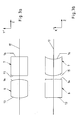
- the arrangement according to the invention comprises one as a laser diode bar executed light source 1 in the X direction side by side arranged and spaced from each other in the X direction having emitting sections.
- the one by one emissive sections 2 outgoing light rays point in a first, the Y direction corresponding direction clearly greater divergence than in a second, the X direction corresponding direction. It is common practice the direction greater divergence "fast-axis" and the direction of smaller divergence To call "slow axis".
- This Collimating means 4 may be a plano-convex cylindrical lens whose Cylinder axis extends in the X direction. In particular, this can Cylinder lens have a very small focal length and very close to be arranged the emitting sections 2.
- a Optical beam transformation device 5 In the propagation direction Z behind the collimation 4 is a Optical beam transformation device 5 according to the invention arranged.
- the device 5 is shown in FIG Embodiment of two separate parts 6, 7, in Propagation direction Z are arranged one behind the other and respectively have an entrance surface and an exit surface.
- the Apparatus 5 will be described below with reference to FIG to Fig. 5 described in more detail.
- Each of the light beams 3 becomes such in the device 5 transforms that its cross-section is reduced and that simultaneously the divergence of the X direction with the divergence of the Y direction is exchanged.
- This has in particular the consequence that the Distance of the individual light beams 3 in the X direction to each other is significantly increased. It thus does not fill with light Areas between each light rays 3.
- a Point is in the direction of propagation Z behind the Device 5, a lens array 8 is provided, which on both the Incident surface as well as on the exit surface lenses 9, 10 have can. It concerns with the lenses 9, 10 to cylindrical lenses whose Cylinder axes extend in the Y direction. Because of this Lens array 8, the individual light beams are widened, so that the distance between the individual light beams in the X direction is much lower.
- a Collimating lens 11 may be provided, for example, a Cylindrical lens includes, the cylinder axis in the X direction extends. From Fig. 1a and Fig. 1b is clearly seen that the individual light beams 12 after passing through the device. 5 in the X direction and thus in the original slow axis no or have only diffraction limited divergence, whereas the individual light beams 12 in the Y direction and thus in the have a divergence in the original fast-axis direction, which is the original divergence in slow-axis direction before passing through the device 5 corresponds. When passing through the Device 5 are thus the divergences in slow-axis and fast-axis directions been exchanged. Therefore, through the collimating lens 11 the residual divergence in the fast-axis direction are collimated. From the collimating lens 11 emerging light beams 12 thus provide in Essentially parallel light that is very easy to focus.
- the light beams 12 substantially the same in both the X and Y directions are extensive.
- the light beams 12 could thus with a in positive Z-direction behind the collimating lens 11 arranged Focusing lens 29 very effective on the entrance surface of a glass fiber 30 are focused.
- the optical beam transformation device 5 is composed as it is For example, from Fig. 2 it can be seen from a first part 6 and a second part 7.
- Fig. 2 is used insofar only for simplifying representation.
- FIG. 3a shows a detail of a section along the Y 'direction, FIG. which is located in Fig. 2.
- Fig. 3b shows a 90 ° rotated view, hence a detail from a section along the also apparent from Fig. 2 X'-direction. Accordingly, the cylinder axes of the extend Cylindrical lenses 13, 14 in the X 'direction.
- the second part 7 of the device 5 has on its entrance surface also convex cylindrical lenses 15.
- the part 7 has concave cylindrical lenses 16 on its exit surface on, their likewise mutually parallel cylinder axes also enclose an angle of 135 ° with the X direction and thus also extend in the Y 'direction.
- f 1 denotes the focal length of the first cylindrical lens 13.
- the parts 6, 7 arranged such that the distance between the second cylindrical lens 14 which is arranged on the exit surface of the part 6, to the third cylindrical lens 15, which is disposed on the entrance surface of the part 7, the focal length f 2 the second cylindrical lens 14 corresponds.
- the optical distance of the first cylindrical lenses 13 to the second cylindrical lenses 14 in the Z direction corresponds to the sum of the two focal lengths f 1 , f 2 of the cylindrical lenses 13, 14. This is clearly evident from FIG. 4a.
- the optical distance of the third cylindrical lenses 15 to the fourth cylindrical lenses 16 in the Z direction corresponds to the focal length f 4 of the fourth cylindrical lenses 16. This is clearly evident from FIG. 4b.
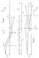
- FIGS. 4a and 4b the imaging behavior of the device 5 can be seen in detail.
- the cylindrical lenses 13, 14, 15, 16 are illustrated schematically by arrows indicating with arrows.
- the focal points of the individual lenses are indicated by crosses.
- Fig. 4a and Fig. 4b the positions of the individual focal lengths f 1 , f 2 , f 3 , f 4 are additionally illustrated.
- the first Cylindrical lenses 13 and the second cylindrical lenses 14 due to Alignment of their cylinder axes in the X'-direction to the distances of Light rays in X'-direction to the optical axis no influence to take. Therefore, the cylindrical lenses 13, 14 of the first part 6 of the Device 5 in Fig. 4b not shown. Analog take also the third cylindrical lenses 15 and the fourth cylindrical lenses 16 of the second Part 7 due to the alignment of their cylinder axes in the Y 'direction to the in Fig. 4a mapped in the Y 'direction to the optical axis spaced light rays have no influence, so that the Cylindrical lenses 15, 16 of the second part 7 in Fig. 4a not shown are.
- the cylindrical lenses 13, 14 of the first part 6 thus act only with respect to the Y 'direction as lenses, whereas with respect to the X'-direction has no influence on passing through them Have light rays.
- the cylindrical lenses 15, 16 act accordingly of the second part 7 only with respect to the X'-direction through them passing light beams, whereas with respect to the Y 'direction no influence on light rays passing through them to have.
- a point spaced apart from the optical axis 17 in the Y 'direction by a distance G y which has a distance from the first cylindrical lens 13 in the Z direction, corresponds to the focal length f 1 of the first cylindrical lens 13 is represented by the imaging system formed by the cylindrical lenses 13, 14 in a point which has a distance B y from the optical axis 17 in the Y 'direction.
- This pixel B y is located behind the second cylindrical lens 14 at a distance in the Z direction, which corresponds to the focal length f 2 of the second cylindrical lens 14.
- Fig. 4b shows the image of a distance G x to the optical axis 17 in the X 'direction spaced points through the imaging system formed by the third and fourth cylindrical lenses 15, 16. Due to the embodiment of the fourth cylindrical lenses 16 as diverging lenses, the imaging system shown in FIG. 4b results in an image which produces a virtual image which, in the illustrated exemplary embodiment, arises in the Z direction exactly at the same location at which the third Cylindrical lenses 15 are located. This virtual image has a distance B x in the X 'direction to the optical axis, which is half as large as the distance G x .
- the lens 13, 14, 15, 16 are arranged, but that the two images generated in the X'-direction and Y'-direction are in the same X'-Y '.
- Level or the same XY plane For example, the image B x does not necessarily arise exactly at the Z position at which the cylindrical lens 15 is located. This image B x can arise behind or in front of the cylindrical lens 15.
- the two parts 6, 7 of the device 5 have cylindrical lenses on their entry surface and their exit surface whose cylinder axes are formed perpendicular to one another.
- a cylindrical lens acting only on the X'-direction like the cylindrical lens 15, could thus be arranged on the exit surface of the first part 6, whereas then a cylinder lens acting only on the Y'-direction like the cylindrical lens 14 on the entrance surface of the second part 7 may be arranged.
- Fig. 5 is again schematically the cross section of a Light beam 3 before passing through the device 5 and the Cross section of the passed through the device 5 Light beam 12 can be seen.
- the Cross section of the light beam 3 approximately halved in both directions has been.
- Fig. 5 shows that the light beam 3 before passing by the device 5 is a substantially rectangular Cross section has. The corners of this rectangular cross section are denoted by the letters a, b, c, d.
- Light beam 12 is also rectangular, with the corners of this Rectangles are denoted by the letters a *, b *, c *, d *. It shows that the previously elongated rectangle in the X direction of the cross section of the light beam 3 in after the Passage in the Y direction extending rectangle of the cross section the light beam 12 was transformed. Furthermore, the Reduction of the cross-section clearly visible.
- the by the Device 5 exerted beam transformation has on the light beam 3 or the light beam 12, a rotation about the Propagation direction Z by 90 ° followed by reflection causes a plane parallel to the propagation direction Z, the passes through the Y direction.
- the effect on the Light beam 3 and the light beam 12 made Beam transformation in addition to the reduction of the cross section a Interchange of divergences in the slow axis direction (X direction) and the fast axis direction (Y direction). This will be out at known in the art devices for Beam transformation usually by simple rotations by 90 ° reached.
- Fig. 6 is another embodiment of an inventive Arrangement can be seen that in principle very similar to that of Fig. 1a and Fig. 1b apparent arrangement is constructed.
- the light source 18 as a semiconductor laser device with a comparatively large heatsink executed.
- the real thing Semiconductor laser element is not apparent in FIG.
- the Focusing lens 29 and the glass fiber 30 is not shown.
- a collimating means 19 can be seen, which as comparatively extended glass substrate with one inside formed as a near-axis collimating lens cylinder lens 20 is formed.
- a device 21 according to the invention for optical Beam transformation provided in the beam direction or Z-direction.
- This device also exists of two parts 22, 23, which, like the parts 6, 7 of the device 5 both on the entrance surface and on the exit surface Cylindrical lenses, which in principle the cylindrical lenses 13, 14, 15, 16, which are clearly visible in FIGS. 3a and 3b.
- a lens array 24 In the positive Z direction is followed by a lens array 24, the has cylindrical lenses only on its exit surface.
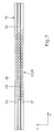
- FIG. 7 again shows the parts 22, 23 of the device 21 together with the collimating means 19 in a negative view Z-direction.
- the individual Cylindrical lenses of which the cylindrical lenses 26 on the exit surface of the part 22 and the cylindrical lenses 27 on the exit surface of the part 23 are provided with reference numerals, substantially square Apertures 28 create in the Z direction with the cylindrical lens 20 of the Collimating agent 19 are aligned.
- the light of the semiconductor laser must through these relatively small square apertures 28 so that the reduction of the cross section of the Light beam 3 when passing through the device 21st or the device 5 is useful.
Landscapes
- Physics & Mathematics (AREA)
- General Physics & Mathematics (AREA)
- Optics & Photonics (AREA)
- Lenses (AREA)
- Semiconductor Lasers (AREA)
- Optical Couplings Of Light Guides (AREA)
- Projection Apparatus (AREA)
- Length Measuring Devices By Optical Means (AREA)
- Optical Communication System (AREA)
- Laser Surgery Devices (AREA)
Priority Applications (7)
| Application Number | Priority Date | Filing Date | Title |
|---|---|---|---|
| DE50313072T DE50313072D1 (de) | 2003-10-30 | 2003-10-30 | Anordnung und Vorrichtung zur optischen Strahlbündeltransformation |
| AT03024780T ATE480792T1 (de) | 2003-10-30 | 2003-10-30 | Anordnung und vorrichtung zur optischen strahlbündeltransformation |
| EP03024780A EP1528425B1 (fr) | 2003-10-30 | 2003-10-30 | Assemblage et appareillage pour la transformation de faisceaux optiques |
| US10/976,006 US7027228B2 (en) | 2003-10-30 | 2004-10-29 | Arrangement and apparatus for optical beam transformation |
| CNB2004100901771A CN100429533C (zh) | 2003-10-30 | 2004-10-29 | 用于进行光束变换的结构和装置 |
| KR1020040087564A KR20050041985A (ko) | 2003-10-30 | 2004-10-30 | 광학적 광선변환을 위한 배열 및 장치 |
| JP2004318587A JP4526924B2 (ja) | 2003-10-30 | 2004-11-01 | 光学的光線変換システムおよび装置 |
Applications Claiming Priority (1)
| Application Number | Priority Date | Filing Date | Title |
|---|---|---|---|
| EP03024780A EP1528425B1 (fr) | 2003-10-30 | 2003-10-30 | Assemblage et appareillage pour la transformation de faisceaux optiques |
Publications (2)
| Publication Number | Publication Date |
|---|---|
| EP1528425A1 true EP1528425A1 (fr) | 2005-05-04 |
| EP1528425B1 EP1528425B1 (fr) | 2010-09-08 |
Family
ID=34400484
Family Applications (1)
| Application Number | Title | Priority Date | Filing Date |
|---|---|---|---|
| EP03024780A Expired - Lifetime EP1528425B1 (fr) | 2003-10-30 | 2003-10-30 | Assemblage et appareillage pour la transformation de faisceaux optiques |
Country Status (7)
| Country | Link |
|---|---|
| US (1) | US7027228B2 (fr) |
| EP (1) | EP1528425B1 (fr) |
| JP (1) | JP4526924B2 (fr) |
| KR (1) | KR20050041985A (fr) |
| CN (1) | CN100429533C (fr) |
| AT (1) | ATE480792T1 (fr) |
| DE (1) | DE50313072D1 (fr) |
Cited By (8)
| Publication number | Priority date | Publication date | Assignee | Title |
|---|---|---|---|---|
| EP1708009A2 (fr) * | 2005-04-01 | 2006-10-04 | Agfa Corporation | Système optique de projection d'une ligne d'illumination, à partir d'un réseau de lasers |
| DE102006018504A1 (de) * | 2006-04-21 | 2007-10-25 | Carl Zeiss Laser Optics Gmbh | Anordnung zum Herstellen einer randscharfen Beleuchtungslinie sowie Anordnung zum Erhöhen der Asymmetrie des Strahlparameterproduktes |
| WO2007140969A1 (fr) * | 2006-06-02 | 2007-12-13 | Limo Patentverwaltung Gmbh & Co. Kg | Dispositif de mise en forme de rayon |
| DE102007057868A1 (de) | 2007-11-29 | 2009-06-04 | Limo Patentverwaltung Gmbh & Co. Kg | Vorrichtung zur Strahlformung |
| EP2708935A1 (fr) * | 2012-09-13 | 2014-03-19 | Fisba Optik Ag | Élément de transformation de faisceau, dispositif de transformation de rayonnement électromagnétique, procédé de fabrication d'un élément de transformation de faisceau et procédé de transformation d'une émission électromagnétique |
| DE102013114083A1 (de) * | 2013-12-16 | 2015-06-18 | Limo Patentverwaltung Gmbh & Co. Kg | Vorrichtung zur Formung von Laserstrahlung |
| WO2021004661A1 (fr) | 2019-07-08 | 2021-01-14 | Limo Display Gmbh | Dispositif de transformation pour le rayonnement laser |
| DE102020109422B4 (de) | 2019-07-08 | 2023-10-05 | Limo Display Gmbh | Transformationsvorrichtung für Laserstrahlung und Laservorrichtung |
Families Citing this family (22)
| Publication number | Priority date | Publication date | Assignee | Title |
|---|---|---|---|---|
| WO2007103898A2 (fr) | 2006-03-03 | 2007-09-13 | Aculight Corporation | Module de pompage par diodes laser à ports de signaux intégrés utilisés pour pomper des fibres amplificatrices |
| US20080013182A1 (en) * | 2006-07-17 | 2008-01-17 | Joerg Ferber | Two-stage laser-beam homogenizer |
| US8587764B2 (en) * | 2007-03-13 | 2013-11-19 | Nikon Corporation | Optical integrator system, illumination optical apparatus, exposure apparatus, and device manufacturing method |
| US20080225257A1 (en) * | 2007-03-13 | 2008-09-18 | Nikon Corporation | Optical integrator system, illumination optical apparatus, exposure apparatus, and device manufacturing method |
| US7891821B2 (en) * | 2007-12-17 | 2011-02-22 | Coherent, Inc. | Laser beam transformer and projector having stacked plates |
| WO2009137703A2 (fr) | 2008-05-08 | 2009-11-12 | Newport Corporation | Procédés et dispositifs de sortie de diode à haute luminosité |
| US7873091B2 (en) * | 2008-08-13 | 2011-01-18 | Institut National D'optique | Laser diode illuminator device and method for optically conditioning the light beam emitted by the same |
| US8075162B2 (en) * | 2008-09-12 | 2011-12-13 | Light Prescriptions Innovators, Llc | Zoom luminaire with compact non-imaging lens-mirror optics |
| DE102008056128B4 (de) * | 2008-11-06 | 2010-10-07 | Trumpf Laser Gmbh + Co. Kg | Optik zur Fokussierung von Diodenlaserstrahlung |
| EP2529452B1 (fr) | 2010-01-22 | 2018-05-23 | II-VI Laser Enterprise GmbH | Homogénéisation d'un rayonnement couplé à des fibres en champ lointain |
| CN101854029A (zh) * | 2010-05-04 | 2010-10-06 | 长春德信光电技术有限公司 | 激光熔覆用半导体激光光源装置 |
| US8644357B2 (en) | 2011-01-11 | 2014-02-04 | Ii-Vi Incorporated | High reliability laser emitter modules |
| US9057498B2 (en) * | 2011-08-15 | 2015-06-16 | General Electric Company | LED light module for backlighting |
| DE102012109937A1 (de) * | 2012-10-18 | 2014-04-24 | Limo Patentverwaltung Gmbh & Co. Kg | Vorrichtung zur Beaufschlagung einer Innenseite eines Zylinders mit Licht sowie Strahltransformationsvorrichtung für eine derartige Vorrichtung |
| US10241335B2 (en) * | 2013-06-12 | 2019-03-26 | Pantec Engineering Ag | Semiconductor laser module |
| US9513483B2 (en) | 2015-03-16 | 2016-12-06 | Igor Gurevich | Beam shaper system for laser diode array |
| KR20170001466A (ko) | 2015-06-26 | 2017-01-04 | 한국전자통신연구원 | 레이저 빔 결합 시스템 |
| US9907636B2 (en) * | 2015-07-01 | 2018-03-06 | 3M Innovative Properties Company | Curing lights with homogenous light patch |
| US10444467B2 (en) * | 2015-11-25 | 2019-10-15 | Himax Technologies Limited | Collimation lens module and light source module using the same |
| DE112017000722T5 (de) * | 2016-02-09 | 2018-10-31 | Mitsubishi Electric Corporation | Strahlformungs-einrichtung und laser-oszillator |
| DE102018211409B4 (de) * | 2018-07-10 | 2021-02-18 | Laserline GmbH | Strahlformende Laseroptik und Lasersystem |
| DE102018211972B4 (de) * | 2018-07-18 | 2020-04-23 | Trumpf Laser Gmbh | Optische Anordnung zur variablen Erzeugung eines Multifoki-Profils, sowie Verfahren zum Betrieb und Verwendung einer solchen Anordnung |
Citations (3)
| Publication number | Priority date | Publication date | Assignee | Title |
|---|---|---|---|---|
| EP1006382A1 (fr) | 1998-10-30 | 2000-06-07 | Lissotschenko, Vitalij | Ensemble et dispositif de conversion optique d'un faisceau lumineux |
| EP1176450A2 (fr) * | 2000-07-28 | 2002-01-30 | Lissotschenko, Vitalij | Dispositif de transformation d' un faisceau optique |
| DE10113019A1 (de) * | 2001-03-17 | 2002-09-19 | Lissotschenko Vitalij | Strahlformungsvorrichtung, Anordnung zur Einkopplung eines Lichtstrahls in eine Lichtleitfaser sowie Strahldreheinheit für eine derartige Strahlformungsvorrichtung oder eine derartige Anordnung |
Family Cites Families (17)
| Publication number | Priority date | Publication date | Assignee | Title |
|---|---|---|---|---|
| US4203652A (en) * | 1977-02-15 | 1980-05-20 | Canon Kabushiki Kaisha | Beam shaping optical system |
| US4293892A (en) * | 1979-12-18 | 1981-10-06 | Polaroid Corporation | Zoom light apparatus |
| DE59009396D1 (de) * | 1989-04-15 | 1995-08-17 | Rodenstock Optik G | Optisches system zur abbildung des lichts von lichtquellen. |
| US4972427A (en) * | 1989-09-14 | 1990-11-20 | Spectra Diode Laboratories, Inc. | Talbot cavity diode laser with uniform single-mode output |
| US5513201A (en) * | 1993-04-30 | 1996-04-30 | Nippon Steel Corporation | Optical path rotating device used with linear array laser diode and laser apparatus applied therewith |
| JP3071360B2 (ja) * | 1993-04-30 | 2000-07-31 | 新日本製鐵株式会社 | リニアアレイレーザダイオードに用いる光路変換器及びそれを用いたレーザ装置及びその製造方法 |
| JPH07287189A (ja) * | 1994-04-18 | 1995-10-31 | Nippon Steel Corp | 光路変換器およびそれを用いたレーザ装置 |
| US5936774A (en) * | 1995-08-29 | 1999-08-10 | Street; Graham S. B. | Autostereoscopic display |
| JP3509534B2 (ja) * | 1998-03-09 | 2004-03-22 | 富士通株式会社 | 光学装置 |
| DE19819333A1 (de) * | 1998-04-30 | 1999-11-04 | Lissotschenko Vitaly | Optisches Emitter-Array mit Kollimationsoptik |
| US6356380B1 (en) * | 1998-11-04 | 2002-03-12 | Barco Graphics Nv | Apparatus for imaging light from multifaceted laser diodes onto a multichannel spatial light modulator |
| US6005717A (en) * | 1998-11-17 | 1999-12-21 | Ceramoptec Industries, Inc. | Diode laser beam combiner system |
| DE19939750C2 (de) * | 1999-08-21 | 2001-08-23 | Laserline Ges Fuer Entwicklung | Optische Anordnung zur Verwendung bei einer Laserdiodenanordnung sowie Laserdiodenanordnung mit einer solchen optischen Anordnung |
| US6407870B1 (en) * | 1999-10-28 | 2002-06-18 | Ihar Hurevich | Optical beam shaper and method for spatial redistribution of inhomogeneous beam |
| JP2003004908A (ja) * | 2001-06-26 | 2003-01-08 | Hamamatsu Photonics Kk | 光学レンズ及び光学システム |
| CA2358169A1 (fr) * | 2001-10-01 | 2003-04-01 | Creo Products Inc. | Methode et appareil d'illumination d'un modulateur spatial de lumiere |
| US6773142B2 (en) * | 2002-01-07 | 2004-08-10 | Coherent, Inc. | Apparatus for projecting a line of light from a diode-laser array |
-
2003
- 2003-10-30 AT AT03024780T patent/ATE480792T1/de active
- 2003-10-30 DE DE50313072T patent/DE50313072D1/de not_active Expired - Lifetime
- 2003-10-30 EP EP03024780A patent/EP1528425B1/fr not_active Expired - Lifetime
-
2004
- 2004-10-29 US US10/976,006 patent/US7027228B2/en not_active Expired - Fee Related
- 2004-10-29 CN CNB2004100901771A patent/CN100429533C/zh not_active Expired - Fee Related
- 2004-10-30 KR KR1020040087564A patent/KR20050041985A/ko not_active Application Discontinuation
- 2004-11-01 JP JP2004318587A patent/JP4526924B2/ja not_active Expired - Fee Related
Patent Citations (3)
| Publication number | Priority date | Publication date | Assignee | Title |
|---|---|---|---|---|
| EP1006382A1 (fr) | 1998-10-30 | 2000-06-07 | Lissotschenko, Vitalij | Ensemble et dispositif de conversion optique d'un faisceau lumineux |
| EP1176450A2 (fr) * | 2000-07-28 | 2002-01-30 | Lissotschenko, Vitalij | Dispositif de transformation d' un faisceau optique |
| DE10113019A1 (de) * | 2001-03-17 | 2002-09-19 | Lissotschenko Vitalij | Strahlformungsvorrichtung, Anordnung zur Einkopplung eines Lichtstrahls in eine Lichtleitfaser sowie Strahldreheinheit für eine derartige Strahlformungsvorrichtung oder eine derartige Anordnung |
Cited By (15)
| Publication number | Priority date | Publication date | Assignee | Title |
|---|---|---|---|---|
| EP1708009A2 (fr) * | 2005-04-01 | 2006-10-04 | Agfa Corporation | Système optique de projection d'une ligne d'illumination, à partir d'un réseau de lasers |
| EP1708009A3 (fr) * | 2005-04-01 | 2006-11-08 | Agfa Corporation | Système optique de projection d'une ligne d'illumination, à partir d'un réseau de lasers |
| DE102006018504A1 (de) * | 2006-04-21 | 2007-10-25 | Carl Zeiss Laser Optics Gmbh | Anordnung zum Herstellen einer randscharfen Beleuchtungslinie sowie Anordnung zum Erhöhen der Asymmetrie des Strahlparameterproduktes |
| US7782535B2 (en) | 2006-06-02 | 2010-08-24 | Limo Patentverwaltung Gmbh & Co. Kg | Device for beam shaping |
| JP2009503596A (ja) * | 2006-06-02 | 2009-01-29 | リモ パテントフェルヴァルトゥング ゲーエムベーハー ウント コー.カーゲー | 光ビーム整形装置 |
| WO2007140969A1 (fr) * | 2006-06-02 | 2007-12-13 | Limo Patentverwaltung Gmbh & Co. Kg | Dispositif de mise en forme de rayon |
| DE102007057868A1 (de) | 2007-11-29 | 2009-06-04 | Limo Patentverwaltung Gmbh & Co. Kg | Vorrichtung zur Strahlformung |
| EP2708935A1 (fr) * | 2012-09-13 | 2014-03-19 | Fisba Optik Ag | Élément de transformation de faisceau, dispositif de transformation de rayonnement électromagnétique, procédé de fabrication d'un élément de transformation de faisceau et procédé de transformation d'une émission électromagnétique |
| WO2014040984A1 (fr) * | 2012-09-13 | 2014-03-20 | Fisba Optik Ag | Élément transformateur de rayonnement, dispositif de transformation d'un rayonnement électromagnétique, procédé de fabrication d'un élément transformateur de rayonnement, et procédé de transformation d'une émission électromagnétique |
| US10095042B2 (en) | 2012-09-13 | 2018-10-09 | Fisba Optik Ag | Beam transformation element, device for transforming electromagnetic radiation, method for producing a beam transformation element, and method for transforming an electromagnetic emission |
| DE102013114083A1 (de) * | 2013-12-16 | 2015-06-18 | Limo Patentverwaltung Gmbh & Co. Kg | Vorrichtung zur Formung von Laserstrahlung |
| US9823479B2 (en) | 2013-12-16 | 2017-11-21 | Limo Patentverwaltung Gmbh & Co. Kg | Device for shaping laser radiation |
| DE102013114083B4 (de) | 2013-12-16 | 2018-10-25 | LIMO GmbH | Vorrichtung zur Formung von Laserstrahlung |
| WO2021004661A1 (fr) | 2019-07-08 | 2021-01-14 | Limo Display Gmbh | Dispositif de transformation pour le rayonnement laser |
| DE102020109422B4 (de) | 2019-07-08 | 2023-10-05 | Limo Display Gmbh | Transformationsvorrichtung für Laserstrahlung und Laservorrichtung |
Also Published As
| Publication number | Publication date |
|---|---|
| KR20050041985A (ko) | 2005-05-04 |
| CN100429533C (zh) | 2008-10-29 |
| JP2005134916A (ja) | 2005-05-26 |
| JP4526924B2 (ja) | 2010-08-18 |
| US7027228B2 (en) | 2006-04-11 |
| ATE480792T1 (de) | 2010-09-15 |
| US20050105189A1 (en) | 2005-05-19 |
| DE50313072D1 (de) | 2010-10-21 |
| CN1611969A (zh) | 2005-05-04 |
| EP1528425B1 (fr) | 2010-09-08 |
Similar Documents
| Publication | Publication Date | Title |
|---|---|---|
| EP1528425B1 (fr) | Assemblage et appareillage pour la transformation de faisceaux optiques | |
| DE502007012156C5 (de) | Vorrichtung zur strahlformung | |
| EP1075719B1 (fr) | Ensemble emetteur optique a systeme optique de collimation | |
| DE19500513C1 (de) | Optische Anordnung zur Verwendung bei einer Laserdiodenanordnung | |
| EP1617275A1 (fr) | Dispositif pour illuminer une surface comprenant une barre de diodes laser et des moyens de transformation de faisceau optique | |
| EP1006382A1 (fr) | Ensemble et dispositif de conversion optique d'un faisceau lumineux | |
| WO1996021877A1 (fr) | Systeme optique s'utilisant dans un systeme de diode laser | |
| EP1839083A1 (fr) | Dispositif d'homogeneisation de la lumiere | |
| DE102009021251A1 (de) | Vorrichtung zur Formung von Laserstrahlung sowie Laservorrichtung mit einer derartigen Vorrichtung | |
| DE102010053781A1 (de) | Vorrichtung zur Umwandlung von Laserstrahlung in Laserstrahlung mit einem M-Profil | |
| EP1555565A1 (fr) | Appareillage pour la transformation optique de rayons d'une matrice linéaire de sources lumineuses | |
| DE102007061358B4 (de) | Vorrichtung zur Formung von Laserstrahlung | |
| WO2005085934A1 (fr) | Dispositif pour generer une zone de focalisation lineaire pour une source de lumiere laser | |
| WO2005085935A1 (fr) | Dispositif pour homogeneiser la lumiere, et systeme d'eclairage ou de focalisation faisant appel a ce dispositif | |
| DE102013114083B4 (de) | Vorrichtung zur Formung von Laserstrahlung | |
| DE102008027229A1 (de) | Vorrichtung zur Strahlformung | |
| DE10118788A1 (de) | Anordnung zur Kollimierung des von einer Laserlichtquelle ausgehenden Lichts sowie Strahltransformationsvorrichtung für eine derartige Anordnung | |
| WO2001069304A1 (fr) | Optique laser et laser a diodes | |
| DE10062453B4 (de) | Verfahren und Vorrichtung zur Überlagerung von Strahlenbündeln | |
| DE19920293A1 (de) | Anordnung und Vorrichtung zur optischen Strahltransformation | |
| DE10106155A1 (de) | Strahlformungsvorrichtung für die Formung des Querschnitts eines Lichtstrahls sowie Anordnung zur Einkopplung eines von einer langgestreckten Laserlichtquelle ausgehenden Lichtstrahls mit einem länglichen Querschnitt in eine Lichtleitfaser | |
| EP1215523A2 (fr) | Système d'irradiation avec transformation du faisceau pour générer une radiation modulée | |
| DE19841285C1 (de) | Optische Anordnung zur Verwendung bei einer Laserdiodenanordnung sowie Diodenlaser | |
| EP1176450A2 (fr) | Dispositif de transformation d' un faisceau optique | |
| DE19936230C2 (de) | Abbildungsvorrichtung |
Legal Events
| Date | Code | Title | Description |
|---|---|---|---|
| PUAI | Public reference made under article 153(3) epc to a published international application that has entered the european phase |
Free format text: ORIGINAL CODE: 0009012 |
|
| AK | Designated contracting states |
Kind code of ref document: A1 Designated state(s): AT BE BG CH CY CZ DE DK EE ES FI FR GB GR HU IE IT LI LU MC NL PT RO SE SI SK TR |
|
| AX | Request for extension of the european patent |
Extension state: AL LT LV MK |
|
| 17P | Request for examination filed |
Effective date: 20051104 |
|
| AKX | Designation fees paid |
Designated state(s): AT BE BG CH CY CZ DE DK EE ES FI FR GB GR HU IE IT LI LU MC NL PT RO SE SI SK TR |
|
| 17Q | First examination report despatched |
Effective date: 20051209 |
|
| RAP1 | Party data changed (applicant data changed or rights of an application transferred) |
Owner name: LIMO PATENTVERWALTUNG GMBH & CO. KG |
|
| GRAP | Despatch of communication of intention to grant a patent |
Free format text: ORIGINAL CODE: EPIDOSNIGR1 |
|
| GRAS | Grant fee paid |
Free format text: ORIGINAL CODE: EPIDOSNIGR3 |
|
| GRAA | (expected) grant |
Free format text: ORIGINAL CODE: 0009210 |
|
| AK | Designated contracting states |
Kind code of ref document: B1 Designated state(s): AT BE BG CH CY CZ DE DK EE ES FI FR GB GR HU IE IT LI LU MC NL PT RO SE SI SK TR |
|
| REG | Reference to a national code |
Ref country code: GB Ref legal event code: FG4D Free format text: NOT ENGLISH |
|
| REG | Reference to a national code |
Ref country code: CH Ref legal event code: EP |
|
| REG | Reference to a national code |
Ref country code: IE Ref legal event code: FG4D Free format text: LANGUAGE OF EP DOCUMENT: GERMAN |
|
| REF | Corresponds to: |
Ref document number: 50313072 Country of ref document: DE Date of ref document: 20101021 Kind code of ref document: P |
|
| REG | Reference to a national code |
Ref country code: NL Ref legal event code: VDEP Effective date: 20100908 |
|
| PG25 | Lapsed in a contracting state [announced via postgrant information from national office to epo] |
Ref country code: FI Free format text: LAPSE BECAUSE OF FAILURE TO SUBMIT A TRANSLATION OF THE DESCRIPTION OR TO PAY THE FEE WITHIN THE PRESCRIBED TIME-LIMIT Effective date: 20100908 |
|
| PG25 | Lapsed in a contracting state [announced via postgrant information from national office to epo] |
Ref country code: CY Free format text: LAPSE BECAUSE OF FAILURE TO SUBMIT A TRANSLATION OF THE DESCRIPTION OR TO PAY THE FEE WITHIN THE PRESCRIBED TIME-LIMIT Effective date: 20100908 Ref country code: SI Free format text: LAPSE BECAUSE OF FAILURE TO SUBMIT A TRANSLATION OF THE DESCRIPTION OR TO PAY THE FEE WITHIN THE PRESCRIBED TIME-LIMIT Effective date: 20100908 |
|
| REG | Reference to a national code |
Ref country code: IE Ref legal event code: FD4D |
|
| PG25 | Lapsed in a contracting state [announced via postgrant information from national office to epo] |
Ref country code: NL Free format text: LAPSE BECAUSE OF FAILURE TO SUBMIT A TRANSLATION OF THE DESCRIPTION OR TO PAY THE FEE WITHIN THE PRESCRIBED TIME-LIMIT Effective date: 20100908 Ref country code: SE Free format text: LAPSE BECAUSE OF FAILURE TO SUBMIT A TRANSLATION OF THE DESCRIPTION OR TO PAY THE FEE WITHIN THE PRESCRIBED TIME-LIMIT Effective date: 20100908 Ref country code: GR Free format text: LAPSE BECAUSE OF FAILURE TO SUBMIT A TRANSLATION OF THE DESCRIPTION OR TO PAY THE FEE WITHIN THE PRESCRIBED TIME-LIMIT Effective date: 20101209 |
|
| PG25 | Lapsed in a contracting state [announced via postgrant information from national office to epo] |
Ref country code: IE Free format text: LAPSE BECAUSE OF FAILURE TO SUBMIT A TRANSLATION OF THE DESCRIPTION OR TO PAY THE FEE WITHIN THE PRESCRIBED TIME-LIMIT Effective date: 20100908 |
|
| BERE | Be: lapsed |
Owner name: LIMO PATENTVERWALTUNG G.M.B.H. & CO. KG Effective date: 20101031 |
|
| PG25 | Lapsed in a contracting state [announced via postgrant information from national office to epo] |
Ref country code: SK Free format text: LAPSE BECAUSE OF FAILURE TO SUBMIT A TRANSLATION OF THE DESCRIPTION OR TO PAY THE FEE WITHIN THE PRESCRIBED TIME-LIMIT Effective date: 20100908 Ref country code: CZ Free format text: LAPSE BECAUSE OF FAILURE TO SUBMIT A TRANSLATION OF THE DESCRIPTION OR TO PAY THE FEE WITHIN THE PRESCRIBED TIME-LIMIT Effective date: 20100908 Ref country code: RO Free format text: LAPSE BECAUSE OF FAILURE TO SUBMIT A TRANSLATION OF THE DESCRIPTION OR TO PAY THE FEE WITHIN THE PRESCRIBED TIME-LIMIT Effective date: 20100908 Ref country code: PT Free format text: LAPSE BECAUSE OF FAILURE TO SUBMIT A TRANSLATION OF THE DESCRIPTION OR TO PAY THE FEE WITHIN THE PRESCRIBED TIME-LIMIT Effective date: 20110110 Ref country code: MC Free format text: LAPSE BECAUSE OF NON-PAYMENT OF DUE FEES Effective date: 20101031 Ref country code: IT Free format text: LAPSE BECAUSE OF FAILURE TO SUBMIT A TRANSLATION OF THE DESCRIPTION OR TO PAY THE FEE WITHIN THE PRESCRIBED TIME-LIMIT Effective date: 20100908 Ref country code: EE Free format text: LAPSE BECAUSE OF FAILURE TO SUBMIT A TRANSLATION OF THE DESCRIPTION OR TO PAY THE FEE WITHIN THE PRESCRIBED TIME-LIMIT Effective date: 20100908 |
|
| PG25 | Lapsed in a contracting state [announced via postgrant information from national office to epo] |
Ref country code: ES Free format text: LAPSE BECAUSE OF FAILURE TO SUBMIT A TRANSLATION OF THE DESCRIPTION OR TO PAY THE FEE WITHIN THE PRESCRIBED TIME-LIMIT Effective date: 20101219 |
|
| PLBE | No opposition filed within time limit |
Free format text: ORIGINAL CODE: 0009261 |
|
| STAA | Information on the status of an ep patent application or granted ep patent |
Free format text: STATUS: NO OPPOSITION FILED WITHIN TIME LIMIT |
|
| 26N | No opposition filed |
Effective date: 20110609 |
|
| PG25 | Lapsed in a contracting state [announced via postgrant information from national office to epo] |
Ref country code: DK Free format text: LAPSE BECAUSE OF FAILURE TO SUBMIT A TRANSLATION OF THE DESCRIPTION OR TO PAY THE FEE WITHIN THE PRESCRIBED TIME-LIMIT Effective date: 20100908 Ref country code: BE Free format text: LAPSE BECAUSE OF NON-PAYMENT OF DUE FEES Effective date: 20101031 |
|
| REG | Reference to a national code |
Ref country code: DE Ref legal event code: R097 Ref document number: 50313072 Country of ref document: DE Effective date: 20110609 |
|
| REG | Reference to a national code |
Ref country code: CH Ref legal event code: PFA Owner name: LIMO PATENTVERWALTUNG GMBH & CO. KG Free format text: LIMO PATENTVERWALTUNG GMBH & CO. KG#DORFSTRASSE 12#36419 GERSTENGRUND (DE) -TRANSFER TO- LIMO PATENTVERWALTUNG GMBH & CO. KG#BOOKENBURGWEG 4-8#44319 DORTMUND (DE) |
|
| REG | Reference to a national code |
Ref country code: DE Ref legal event code: R082 Ref document number: 50313072 Country of ref document: DE Representative=s name: FRITZ PATENT- UND RECHTSANWAELTE, DE Effective date: 20120531 Ref country code: DE Ref legal event code: R081 Ref document number: 50313072 Country of ref document: DE Owner name: LIMO PATENTVERWALTUNG GMBH & CO. KG, DE Free format text: FORMER OWNER: LIMO PATENTVERWALTUNG GMBH & CO. KG, 36419 GERSTENGRUND, DE Effective date: 20120531 Ref country code: DE Ref legal event code: R082 Ref document number: 50313072 Country of ref document: DE Representative=s name: FRITZ PATENT- UND RECHTSANWAELTE PARTNERSCHAFT, DE Effective date: 20120531 |
|
| REG | Reference to a national code |
Ref country code: FR Ref legal event code: CA Effective date: 20120730 |
|
| PG25 | Lapsed in a contracting state [announced via postgrant information from national office to epo] |
Ref country code: LU Free format text: LAPSE BECAUSE OF NON-PAYMENT OF DUE FEES Effective date: 20101030 Ref country code: HU Free format text: LAPSE BECAUSE OF FAILURE TO SUBMIT A TRANSLATION OF THE DESCRIPTION OR TO PAY THE FEE WITHIN THE PRESCRIBED TIME-LIMIT Effective date: 20110309 Ref country code: BG Free format text: LAPSE BECAUSE OF FAILURE TO SUBMIT A TRANSLATION OF THE DESCRIPTION OR TO PAY THE FEE WITHIN THE PRESCRIBED TIME-LIMIT Effective date: 20100908 |
|
| PG25 | Lapsed in a contracting state [announced via postgrant information from national office to epo] |
Ref country code: TR Free format text: LAPSE BECAUSE OF FAILURE TO SUBMIT A TRANSLATION OF THE DESCRIPTION OR TO PAY THE FEE WITHIN THE PRESCRIBED TIME-LIMIT Effective date: 20100908 |
|
| PG25 | Lapsed in a contracting state [announced via postgrant information from national office to epo] |
Ref country code: BG Free format text: LAPSE BECAUSE OF FAILURE TO SUBMIT A TRANSLATION OF THE DESCRIPTION OR TO PAY THE FEE WITHIN THE PRESCRIBED TIME-LIMIT Effective date: 20101208 |
|
| PGFP | Annual fee paid to national office [announced via postgrant information from national office to epo] |
Ref country code: GB Payment date: 20131021 Year of fee payment: 11 Ref country code: AT Payment date: 20131011 Year of fee payment: 11 Ref country code: CH Payment date: 20131021 Year of fee payment: 11 Ref country code: FR Payment date: 20131022 Year of fee payment: 11 Ref country code: DE Payment date: 20131031 Year of fee payment: 11 |
|
| REG | Reference to a national code |
Ref country code: DE Ref legal event code: R119 Ref document number: 50313072 Country of ref document: DE |
|
| REG | Reference to a national code |
Ref country code: CH Ref legal event code: PL |
|
| REG | Reference to a national code |
Ref country code: AT Ref legal event code: MM01 Ref document number: 480792 Country of ref document: AT Kind code of ref document: T Effective date: 20141030 |
|
| GBPC | Gb: european patent ceased through non-payment of renewal fee |
Effective date: 20141030 |
|
| PG25 | Lapsed in a contracting state [announced via postgrant information from national office to epo] |
Ref country code: LI Free format text: LAPSE BECAUSE OF NON-PAYMENT OF DUE FEES Effective date: 20141031 Ref country code: GB Free format text: LAPSE BECAUSE OF NON-PAYMENT OF DUE FEES Effective date: 20141030 Ref country code: CH Free format text: LAPSE BECAUSE OF NON-PAYMENT OF DUE FEES Effective date: 20141031 Ref country code: DE Free format text: LAPSE BECAUSE OF NON-PAYMENT OF DUE FEES Effective date: 20150501 |
|
| REG | Reference to a national code |
Ref country code: FR Ref legal event code: ST Effective date: 20150630 |
|
| PG25 | Lapsed in a contracting state [announced via postgrant information from national office to epo] |
Ref country code: FR Free format text: LAPSE BECAUSE OF NON-PAYMENT OF DUE FEES Effective date: 20141031 Ref country code: AT Free format text: LAPSE BECAUSE OF NON-PAYMENT OF DUE FEES Effective date: 20141030 |