EP1528342A2 - Procédé pour séchage de matériau et dispositif pour mettre en oeuvre le procédé - Google Patents
Procédé pour séchage de matériau et dispositif pour mettre en oeuvre le procédé Download PDFInfo
- Publication number
- EP1528342A2 EP1528342A2 EP04405298A EP04405298A EP1528342A2 EP 1528342 A2 EP1528342 A2 EP 1528342A2 EP 04405298 A EP04405298 A EP 04405298A EP 04405298 A EP04405298 A EP 04405298A EP 1528342 A2 EP1528342 A2 EP 1528342A2
- Authority
- EP
- European Patent Office
- Prior art keywords
- solvent
- flow channel
- vacuum
- heated
- steam
- Prior art date
- Legal status (The legal status is an assumption and is not a legal conclusion. Google has not performed a legal analysis and makes no representation as to the accuracy of the status listed.)
- Granted
Links
Images


Classifications
-
- F—MECHANICAL ENGINEERING; LIGHTING; HEATING; WEAPONS; BLASTING
- F26—DRYING
- F26B—DRYING SOLID MATERIALS OR OBJECTS BY REMOVING LIQUID THEREFROM
- F26B5/00—Drying solid materials or objects by processes not involving the application of heat
- F26B5/04—Drying solid materials or objects by processes not involving the application of heat by evaporation or sublimation of moisture under reduced pressure, e.g. in a vacuum
-
- F—MECHANICAL ENGINEERING; LIGHTING; HEATING; WEAPONS; BLASTING
- F26—DRYING
- F26B—DRYING SOLID MATERIALS OR OBJECTS BY REMOVING LIQUID THEREFROM
- F26B21/00—Arrangements for supplying or controlling air or other gases for drying solid materials or objects
- F26B21/40—Arrangements for supplying or controlling air or other gases for drying solid materials or objects using gases other than air
- F26B21/471—Arrangements for supplying or controlling air or other gases for drying solid materials or objects using gases other than air condensing vapours onto the surface of the materials to be dried
Definitions
- the invention is based on a process for drying good, in particular solid insulation of an electrical appliance, according to The preamble of claim 1.
- the invention also relates to a Apparatus for carrying out the method.
- the method of the type mentioned is DE 30 14 831 A removable.
- An in described in this prior art, according to the vapour phase method working drying device for isolierölgetränkte insulations has a the on to be dried isolations receiving evacuable autoclave, in the a cascade evaporator is arranged.
- This cascade evaporator is in essentially vertically aligned and contains one of a plate and a Partition wall limited flow channel. At the plate are heating coils and Guiding plates arranged.
- the cascade evaporator is solvent by means of a pump fed, which in a arranged outside the autoclave preheater was heated.
- the preheated solvent trickles with the help of the baffles along the plate from top to bottom.
- the solvent evaporates to the Heating coils.
- the forming solvent vapor flows due to chimney effect in the flow channel vertically upwards and is via a steam inlet in the Insulators containing usable space of the autoclave out.
- the present invention is based on the object, the energy consumption and to reduce the lead time of the method of the type mentioned above and at the same time provide devices which in a particularly advantageous manner to Implementation of this method are suitable.
- the guided in the vacuum tank and heated solvent in a formed in the manner of a venturi flow channel injected In this case, a predominantly solvent vapor-containing and by a Constriction of the flow channel guided beam formed, which is due to Suction intense with an already existing in the vacuum container share Solvent vapor mixes.
- the temperature of the From the flow channel passing solvent vapor can be controlled very precisely.
- the flow stimulated by the jet is an optimal one Circulation and turbulence of the solvent vapor in the vacuum tank ensured. As a result, the amount of energy required to heat the drying material and greatly reduces the heating time.
- a particularly short cycle time is achieved when the heated solvent in injected through the venturi solvent vapor stream is injected.
- the effect of the injected solvent will be the speed and the Turbulence of the guided in the Venturi nozzle solvent vapor stream substantially elevated.
- the increased solvent vapor velocity is due the Jet Sign also maintained towards the end of the heating phase, which is a shorter heating time in the upper temperature range and even smaller Temperature difference across the drying object ensures, reducing the quality of the Drying is significantly improved.
- the aforementioned is guided in the Venturi nozzle Generates solvent vapor stream in a vacuum vessel arranged in the evaporator, because then by the action of the injected solvent of the Evaporator generated solvent vapor is rapidly sucked away from the evaporator, resulting in smaller pressure loss in this evaporator and thus leads to increased efficiency.
- the solvent vapor stream can also be in an outside of the vacuum vessel arranged evaporator generated and through the wall into the interior of the Vacuum container are guided.
- the Jet Sign then the Solvent vapor better from a guided in the vacuum tank Solvent vapor line sucked, resulting in smaller pressure drop between external Evaporator and vacuum vessel and thus also leads to increased efficiency.
- the heated solvent at the bottleneck of the Venturi nozzle in the Injected flow channel At the bottleneck, this points into the flow channel injected solvent particularly high speed up.
- This high Speed calls for a great vacuum and thus a strong jet effect out, i. a particularly strong sucking a in the vacuum container when Heating the drying material formed mixed steam flow of solvent and Water vapor in the injected solvent.
- the inventive method is characterized by a particularly high Efficiency, when in the guided inside the vacuum tank Mixed steam flow cold solvent is injected.
- cold Solvent such as in a vacuum container arranged in the condensation space
- This increases the proportion of water vapor in the Condensation on and consequently has less solvent vapor in one outside the vacuum tank condenser as condensate be deposited, whereby the energy requirement of the process in addition is reduced.
- the mixed steam is strongly sucked because of the blasting effect and due to intensive mixing a high heat recuperation by heating the achieved injected cold solvent.
- a further reduction of the energy requirement of erfindungefflessen method is achieved in that the mixed steam flow out of the vacuum tank and condensed outside the container in two or more stages, and that with the output in a first of the stages in the condensing of mixed steam Condensation heat heating air is heated.
- the solvent steam generator contains a inside the Vacuum container arranged and designed in the manner of a Venturi nozzle Flow channel and a guided in the flow channel device for Injecting heated solvent into the flow channel.
- this device is characterized when the Injection device at the bottleneck of the Venturi nozzle in the flow channel empties.
- the injection device an opening with injection openings in the flow channel Solventverteilkanal and / or at least one held in the interior of the flow channel injection nozzle.
- Heating energy can be saved and thus the efficiency of the process on be improved if provided for heating the vacuum tank Heating device is designed as a water heater for the solvent.
- a simple control of temperature and mixing ratio of the Flow channel escaping solvent vapor can be achieved in that a directional channel limiting the flow channel, changing the inflow and / or Outflow cross section of the flow channel is adjustable.
- this condensation space as a flow channel for the mixed gas formed and has inflow as an inflow channel of a venturi acting sheet on and / or a drain sheet and / or downstream Baffle.
- the required heating energy is additionally reduced by the fact that the Condensing device arranged outside the vacuum container, having air-cooled condenser for generating heating air.
- the vacuum container as a housing of a transformer executed and in a preferably heatable with air isolierhaus arranged.
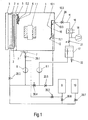
- the drying devices shown in the figures serve to dry good, in particular the solid insulation of one or more electrical devices as well removing any insulating oil that may be present in the insulation.
- the Drying device according to Fig.1 contains a vacuum-tight running container 1, which is equipped with a solid insulation containing electrical device, For example, a transformer, or - as shown - only with the Solid insulating containing active part 1.1 is loaded.
- the vacuum container 1 can be heated by means of heating pipes 2.
- the heating energy is in one Heat generator 3 on a flowing in the tubes 2 heat transfer medium for heating of the vacuum container 1 transmitted.
- the heating pipes 2 are of a double jacket surrounded and form together with the jacket a Solventerhitzer 4 a Solvent steam generator.
- the solvent heater cold solvent is heated.
- the solvent is generally a light oil with a much higher boiling point than water and a much lower boiling point than any in the Solid insulation existing insulating oil.
- the heated solvent is poured over an in 1 unsigned Solventitatisön in one within the Vacuum container 1 lying, optionally tubular, Solventverteilkanal 5 of Solventdampfer Wegers out.
- the solvent distribution channel 5 can with advantage as exposed pipe with injection openings and or Injectors are formed. This will be a cost effective device reached.
- the Solventverteilkanal 5 has injection openings or injectors for the solvent on.
- the straightening plate 6 can through Turning and / or moving in its position can be changed. This can be done the upstream of the nozzle throat of the Venturi nozzle located inflow and the downstream of the nozzle throat located Abströmquerites of Flow channel 5.2 enlarge or reduce.
- the vacuum container 1 has down in its bottom an opening into a drain tank 7 drain opening for condensed solvent on and optionally from the solvent from the Solid insulation washed out insulating oil.
- a Switch executed fill level indicator 7.1 arranged in the drain tank 7 .
- the drain tank 7 is via Shut-off valve 20.1 connected to a feed pump 8.
- the exit of the Feed pump 8 is connected via shut-off valve 20.3 with the Solventerhitzer 4 or alternatively via shut-off valve 20.6 with a solvent storage tank 9 or via Shut-off valve 20.7 with an oil tank 19 for receiving the optionally existing insulating oil, which during drying of the material to be dried 1.1 by the Solvent removed from the solid insulations and subsequently by distillation was separated from the solvent.
- the flow channel 5.2 is in the vacuum tank 1 a Condensation device arranged with a condensation chamber 10 for Heat recuperation, a baffle 10.1, baffles 10.2 and injectors 11.
- the condensation space 10 is down to the inside of the vacuum container. 1 open and has at its upper end a through the wall of the container. 1 guided outlet opening 10.3, which via a mixing steam line 15 and a Dampfabsperrventil 20 leads to a mixed steam condenser 16.
- the Mischdampfkondensator 16 has two outputs, one of which with a Vacuum system 18 and the other via a check valve 21 with a separation tank 17 is connected.
- the separation vessel 17 has two outputs, one of which on one of the removal of water serving discharge valve 22 acts and the other is connected to the input of a Solvent technicallypumpe 8.1 whose output optionally via a shut-off valve 20.5 to the injection nozzles 11, or over Shut-off valves 20.4 and 20.6 leads to the solvent reservoir tank 9.
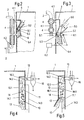
- the heated solvent as intensive Solvent flow 5.3 from the Solventverteilkanal 5 in the flow channel 5.2 emerge and there with a solvent and water vapor containing Mixed steam from the interior of the container to a predominantly solvent vapor containing steam containing 5.4.
- the flow channel 5.2 can over the extend entire length and / or width of a wall of the container and possibly also consist of several short sections. Is the Solventverteilkanal as exposed pipe with injection openings or injectors trained, it is through the emerging from the manifold, expanding and partially evaporating solvent, the mixed steam in the flow channel on both sides of the Distributor pulled in over.
- the heating pipes 2 of the Solventerhitzers. 4 mainly oriented horizontally and that is the flow channel 5.2 limiting straightening plate 6 rotatably formed.
- the rotation of the straightening plate 6 can be achieved by a mechanical adjustment 6.2, which via a Lever gear on the pivotally mounted at a point 6.1 straightening plate 6 acts.
- the straightening plate between two positions 5.5 resp.
- the injected Solvent 14 and the condensed solvent vapor 14.1 flow to the drain pan 7 and be pumped with the feed pump 8, while remaining mixed steam 14.2 from the mixing steam flow 13 via the mixing steam line 15 from the Condensation space 10 is removed and led to a mixed steam condenser 16 becomes.
- the operation of the device is as follows: With the vacuum system 18, the vacuum container 1, the mixed steam condenser 16 and the separation tank 17 are evacuated. At the same time, the solvent supply tank 9 draws solvent via the shut-off valves 20.6 and 20.3 and the solvent heater 4 into the vacuum container 1 until the filling level indicator 7.1 is flooded.
- the solvent present in the vacuum tank 1 is circulated by the feed pump 8 and heated in the solvent heater 4 to a temperature slightly above a predetermined drying temperature. The heated solvent is heated to normal or possibly higher pressure.
- the pressure in the solvent 5.3 drops sharply and evaporates a portion of the heated solvent with simultaneous cooling by the amount of its heat of vaporization.
- the resulting solvent vapor 5.4 condenses on the active part and heats it with simultaneous evaporation of the water contained in the solid insulation, resulting in the formation of the solvent and steam containing mixed steam in the vacuum vessel 1.
- resulting and optionally insulating solvent-containing solvent condensate is fed back to the Solventverteilkanal 5 with the feed pump 8 via the solvent heater 4 for evaporation.
- the solvent 5.3 is advantageously injected at the nozzle throat via the injection openings 5.1 in the flow channel 5.2. This results in a particularly high flow velocity and a correspondingly high negative pressure. This leads to a jet effect, through which the mixed steam present in the vacuum tank 1 is sucked into the flow channel 5.2.
- the sucked mixed steam mixes with the injected solvent 5.3 and the solvent vapor 5.4 formed during injection.
- the injection nozzles 11, 11.1 is stored in the separation tank 17 cold solvent fed with the feed pump 8.1 via shut-off valve 20.5 and in the Condensation space 10 injected.
- the large surface of the injected cold solvent 14 condenses the solvent vapor component into the Condensation space 10 sucked mixed steam 13 to form the condensed solvent 14.1.
- This can be done in an advantageous manner Enrich water vapor in the condensation chamber 10. It will be less Solvent vapor led to the mixed steam condenser 16. It becomes so energy saved, which on the one hand for heating the solvent and the other to Cooling of the mixed steam condenser 16 is required.
- the injected solvent and the condensed solvent vapor flow over the drain tank 7 Feed pump 8 and are fed via shut-off valve 20.3 the solvent heater 4.
- the condensation chamber 10 with steam enriched solvent vapor is controlled by the Dampfabsperrventil 20 the mixed steam condenser 16th fed and condensed. This resulting air leakage is with the vacuum system 18th pumped out.
- the solvent and water-containing condensate is then by means of Sedimentation separated in the separation vessel 17 and the solvent with the pump 8.1 via Shut-off valve 20.5 fed back to the injectors 11, 11.1.
- the feed pump 8 is turned off and the Steam shut-off valve 20 fully open.
- condensation of solvent and Water vapor in the mixed steam condenser 16 is the pressure in the vacuum vessel. 1 lowered and at the same time accumulating in the separation tank 17 solvent condensate with the feed pump 8.1 via the valves 20.4, 20.6 supplied to the solvent reservoir tank 9.
- the shut-off valve 21 is closed and the Pressure in the vacuum container 1 with the vacuum pump 18 for a given Period lowered to low vacuum levels.
- the vacuum tank 1 is vented and then the dried material 1.1 is the Vacuum tank 1 removed.
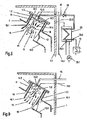
- the Vacuum container 1 designed as a housing of a transformer, which is the Drying material, also in this case containing the solid insulation active part 1.1 of the transformer absorbs.
- the transformer housing 1 is in one réelleisolierhaus 1.5 arranged, which are heated by the heat generator 3 can.
- the heat generator 3 is designed as an air heater. The heating energy is supplied through the tubes 2. Through the tubes 2 heated air is used as a heat transfer medium with the help of a hot air fan 3.1 via a housing feedthrough 3.3 into Heat insulation house 1.5 transported. About a housing bushing 3.2 is air the heat insulating housing 1.5 back to the air heater and again heated.
- the Heating pipes 2 are surrounded by a double jacket and are from the heat generator. 3 heated both the transformer housing 1 and the solvent.
- the transformer housing. 1 but with cover flanges 1.3 vacuum-sealed openings 1.2, through which openings otherwise the power connections of the active part 1.1 are guided.
- one of these openings 1.2 is that of the Solventerhitzer 4 on the Solvent connection line 4.1 Flow channel supplied with hot solvent 5.2 arranged.
- the Solventdampfer Weger now one at the Nozzle throat of the venturi nozzle arranged and in the direction of the nozzle axis aligned injection nozzle 5.7, which via the line 4.1 with hot solvent is fed.
- Further solvent steam generators each with a flow channel and with one or possibly also with several injectors 5.7 can be provided other openings 1.2 of the transformer housing 1.
- the flow channel is 5.2 substantially formed axially symmetrical and is limited by a fixed and the large part around the axis bent Venturiblech 6.3 as well as by the adjustable executed straightening plate 6.
- Deflector 6.4 On the downstream side is on the straightening plate 6 in addition Deflector 6.4 arranged. By the sheet 6.4 is from the channel 5.2 passing, not evaporated solvent to the wall of the transformer housing. 1 guided and can quickly via a provided in the bottom drain port 1.4 ( Figure 6) removed again from the housing 1 and the solvent heater 4 are supplied.
- transformer housing 1 In a further opening 1.2 transformer housing 1 is the condensation chamber 10 arranged.
- Two embodiments of this condensation space are from the Figures 8 and 9 can be seen, wherein the embodiment of Figure 8 is largely the Embodiment corresponds to Figure 5 and the Fig.9 largely that according to Fig.4.
- the embodiment of Figure 8 is still an air-cooled Capacitor 23 shown, which with the outlet opening 10.3 of the Condensation space 10 connected via the line 15 and the Mixed steam condenser 16 to form an additional condensation stage for the enriched steam containing mixed steam 14.2 is connected upstream.
- Air heated in the air-cooled condenser 23 is transferred by a fan 23.1 an inlet opening 23.2 for heating purposes in the planteisoliergephase 1.4 transported.
- the drying device 6 shows the assembled transformer in the townisoliergephaseuse first are introduced and instead of housing bushings for the Power connections of the active part 1.1 for carrying the line 4.1 and the Injector 5.7 and to complete the condensation chamber 10 needed Connection flanges 1.3 mounted.
- Condensate drain is the Interior of the transformer housing 1 with the other components of the Drying device connected.
- the drying process can now - as in the embodiment the drying device according to Fig.1 described - be performed.
- the drying device in the vacuum tank 1 a generally as a cascade evaporator trained Solventdampfer Weger 24 arranged. Become this steam generator supplied from the outside through the wall of the vacuum vessel 1 solvent and heat. The amount of solvent supplied is by means of a Solventabsperrventils 20.9 controlled. The heat is placed in an outside of the vacuum tank Heat generator 24.2 formed. Solvent vapor 29 formed in the evaporator 24 flows through a solvent vapor outlet 24.1 in the flow channel 5.2.
- Reference numeral 25 is an outside of the vacuum container 1 befindaji Solvent heater, preheated in the solvent and the preheated Solvent via a Solventabsperrventil 20.8 dosed in the flow channel 5.2 located Solventverteilkanal 5 is performed. Injectors 5.7 of Solventverteilkanals 5 are arranged in the region of the bottleneck of the venturi.
- the preheated solvent 5.3 injected in the direction of the solvent vapor stream 29 sucks the Solventdampf from the evaporator 24 due to Jet Sign and so increases its flow velocity.
- the speed of the Flow channel 5.2 already increased mixed steam flow 30 increases.
- the from the Flow channel 5.2 passing steam flow 5.4 therefore has a high Flow rate and good turbulence. This results in a higher flow speed and better turbulence of the Vacuum vessel circulating solvent vapor stream than conventional Method.
- the drying times are at the same time low Energy consumption reduced.
- the Jet Angel remains the desired high Solvent vapor velocity in the autoclave towards the end of the heating phase receive. This leads to a shorter heating time in the upper temperature range and Accordingly, also provides a small temperature difference over the Drying 1.1 and thus an improved drying quality safely.
- Solvent evaporator 26 for example, a large evaporator or a Downpipe evaporator
- the Jet Sign of injected in the direction of the steam flow 29 heated Solvents are analogous to the embodiment according to FIG. 10 of the solvent vapor the steam line and the mixed steam are sucked out of the autoclave 1 and become so the flow velocity and the turbulence of the steam flow in 5.4 advantageously increased.
Landscapes
- Engineering & Computer Science (AREA)
- Mechanical Engineering (AREA)
- General Engineering & Computer Science (AREA)
- Health & Medical Sciences (AREA)
- Life Sciences & Earth Sciences (AREA)
- Molecular Biology (AREA)
- Drying Of Solid Materials (AREA)
Priority Applications (1)
| Application Number | Priority Date | Filing Date | Title |
|---|---|---|---|
| EP04405298A EP1528342B1 (fr) | 2003-10-31 | 2004-05-10 | Procédé pour séchage de matériau et dispositif pour mettre en oeuvre le procédé |
Applications Claiming Priority (3)
| Application Number | Priority Date | Filing Date | Title |
|---|---|---|---|
| EP03405783 | 2003-10-31 | ||
| EP03405783 | 2003-10-31 | ||
| EP04405298A EP1528342B1 (fr) | 2003-10-31 | 2004-05-10 | Procédé pour séchage de matériau et dispositif pour mettre en oeuvre le procédé |
Publications (3)
| Publication Number | Publication Date |
|---|---|
| EP1528342A2 true EP1528342A2 (fr) | 2005-05-04 |
| EP1528342A3 EP1528342A3 (fr) | 2005-07-20 |
| EP1528342B1 EP1528342B1 (fr) | 2006-08-30 |
Family
ID=34424789
Family Applications (1)
| Application Number | Title | Priority Date | Filing Date |
|---|---|---|---|
| EP04405298A Expired - Lifetime EP1528342B1 (fr) | 2003-10-31 | 2004-05-10 | Procédé pour séchage de matériau et dispositif pour mettre en oeuvre le procédé |
Country Status (1)
| Country | Link |
|---|---|
| EP (1) | EP1528342B1 (fr) |
Cited By (3)
| Publication number | Priority date | Publication date | Assignee | Title |
|---|---|---|---|---|
| EP2525178A1 (fr) * | 2011-05-18 | 2012-11-21 | Micavac AG | Procédé de séchage d'un élément actif comprenant des isolations de matière solide d'un appareil électrique pouvant être rempli avec de l'huile d'imprégnation et dispositif destiné à l'exécution de ce procédé |
| DE102014101298A1 (de) * | 2014-02-03 | 2015-08-06 | Inter-Consult Gmbh | Verfahren und Vorrichtung zum Aufheizen, Reinigen und Trocknen von Trocknungsgütern |
| WO2019102399A3 (fr) * | 2017-11-22 | 2019-10-17 | Sociedad De Ingeniería Ambiental Ltda | Équipement d'extraction par solvant permettant une utilisation efficace de l'énergie par réutilisation du ou des solvants |
Families Citing this family (2)
| Publication number | Priority date | Publication date | Assignee | Title |
|---|---|---|---|---|
| EP2148157B1 (fr) | 2008-07-25 | 2013-02-27 | Paul Gmeiner | Dispositif de chauffage et de séchage d'une marchandise selon le procédé de phase vapeur |
| EP3029403B1 (fr) | 2014-12-03 | 2017-12-20 | Paul Gmeiner | Procédé et dispositif de séchage de l'isolation de matière solide de la pièce active d'un appareil électrique selon le procédé de phase gazeuse |
Citations (2)
| Publication number | Priority date | Publication date | Assignee | Title |
|---|---|---|---|---|
| DE3014831A1 (de) | 1980-02-29 | 1981-09-17 | Micafil AG, 8048 Zürich | Kaskadenverdampfer fuer kondensations-trocknungsvorrichtungen |
| US20020184784A1 (en) | 2000-09-05 | 2002-12-12 | Helmut Strzala | Device for preparing transformers |
Family Cites Families (5)
| Publication number | Priority date | Publication date | Assignee | Title |
|---|---|---|---|---|
| DE1211553B (de) * | 1958-03-18 | 1966-02-24 | Konrad Kieferle | Trockner, z. B. Trocknungsschrank |
| FR1398812A (fr) * | 1964-03-24 | 1965-05-14 | Vide Soc Gen Du | Perfectionnements au séchage des matières isolantes |
| DE19608974C1 (de) * | 1996-03-08 | 1997-03-06 | Sicowa Verfahrenstech | Verfahren zum Trocknen von Beschickungsgut während seiner Druckdampfbehandlung in einem Autoklav und Autoklav hierfür |
| EP1253389B1 (fr) * | 2001-04-24 | 2005-11-16 | ABB Schweiz AG | Procédé de séchage d'une pièce active, et dispositif pour la mise en oeuvre de ce procédé |
| US6702101B2 (en) * | 2001-12-21 | 2004-03-09 | Spraying Systems Co. | Blower operated airknife with air augmenting shroud |
-
2004
- 2004-05-10 EP EP04405298A patent/EP1528342B1/fr not_active Expired - Lifetime
Patent Citations (2)
| Publication number | Priority date | Publication date | Assignee | Title |
|---|---|---|---|---|
| DE3014831A1 (de) | 1980-02-29 | 1981-09-17 | Micafil AG, 8048 Zürich | Kaskadenverdampfer fuer kondensations-trocknungsvorrichtungen |
| US20020184784A1 (en) | 2000-09-05 | 2002-12-12 | Helmut Strzala | Device for preparing transformers |
Non-Patent Citations (3)
| Title |
|---|
| GMEINER P.K.: "Modern vapour drying processes and plants", MICAFIL VAKUUMTECHNIK AG, February 1992 (1992-02-01), ZÜRICH |
| MEYERS S.D.; KELLY J.J.; PARISH P.H.: "Guide to Transformer Maintenance", 1981, TRANSFORMER MAINTENANE INSTITUTE,DIVISION,S.D.MEYERS,INC.AKRON, OHIO, pages: 496 |
| OESCH G.; SCHATZL H.: "Die Solventdampftrocknung und Leistungstransformatoren", MICAFIL AG, August 1976 (1976-08-01), ZÜRICH |
Cited By (4)
| Publication number | Priority date | Publication date | Assignee | Title |
|---|---|---|---|---|
| EP2525178A1 (fr) * | 2011-05-18 | 2012-11-21 | Micavac AG | Procédé de séchage d'un élément actif comprenant des isolations de matière solide d'un appareil électrique pouvant être rempli avec de l'huile d'imprégnation et dispositif destiné à l'exécution de ce procédé |
| DE102014101298A1 (de) * | 2014-02-03 | 2015-08-06 | Inter-Consult Gmbh | Verfahren und Vorrichtung zum Aufheizen, Reinigen und Trocknen von Trocknungsgütern |
| DE102014101298B4 (de) | 2014-02-03 | 2019-03-14 | Inter-Consult Gmbh | Verfahren und Vorrichtung zum Aufheizen, Reinigen und Trocknen von Trocknungsgütern |
| WO2019102399A3 (fr) * | 2017-11-22 | 2019-10-17 | Sociedad De Ingeniería Ambiental Ltda | Équipement d'extraction par solvant permettant une utilisation efficace de l'énergie par réutilisation du ou des solvants |
Also Published As
| Publication number | Publication date |
|---|---|
| EP1528342A3 (fr) | 2005-07-20 |
| EP1528342B1 (fr) | 2006-08-30 |
Similar Documents
| Publication | Publication Date | Title |
|---|---|---|
| DE19754897A1 (de) | Trocknungsvorrichtung und Verfahren zur Behandlung der Oberfläche eines Substrates | |
| DE19503591A1 (de) | Verfahren und Vorrichtung zur Extraktions-Behandlung einer Probe | |
| DE2544343B2 (de) | Verfahren zur Herstellung von weißem Zement und Anlage zur Durchführung des Verfahrens | |
| DE10234710B4 (de) | System zum Trocknen von Halbleitersubstraten | |
| EP1528342B1 (fr) | Procédé pour séchage de matériau et dispositif pour mettre en oeuvre le procédé | |
| DE2366052A1 (de) | Tabaktrockner | |
| EP2148157B1 (fr) | Dispositif de chauffage et de séchage d'une marchandise selon le procédé de phase vapeur | |
| EP0752567B1 (fr) | Procédé de séchage d'une isolation solide d'un appareil électrique, et dispositif pour la mise en oeuvre de ce procédé | |
| EP2525178B1 (fr) | Procédé de séchage d'un élément actif comprenant des isolations de matière solide d'un appareil électrique pouvant être rempli avec de l'huile d'imprégnation et dispositif destiné à l'exécution de ce procédé | |
| EP3165859A1 (fr) | Dispositif de refroidissement à vide et procédé pour le refroidissement à vide des aliments | |
| EP2308576B1 (fr) | Evaporateur | |
| DE2850019A1 (de) | Verfahren und einrichtung zum abscheiden von kondensierten und/oder kondensierbaren komponenten aus einem rohgasgemisch | |
| DE19712993A1 (de) | Apparat zum Aufwärmen und Entgasen von Wasser | |
| DE3001995C2 (fr) | ||
| DE19502489C2 (de) | Wärmeverbraucherstation | |
| EP0463448A1 (fr) | Procédé et dispositif de chauffage et de dégazage à multiple effet de l'eau | |
| EP3029403B1 (fr) | Procédé et dispositif de séchage de l'isolation de matière solide de la pièce active d'un appareil électrique selon le procédé de phase gazeuse | |
| DE649672C (de) | Verfahren und Anlage zum Verdampfen von Fluessigkeit | |
| DE2724268C3 (de) | Verfahren und Vorrichtung zur Regelung der Trocknung von Ware | |
| DE10245935A1 (de) | Entlüftungs-/Entgasungssystem für Kraftwerkskondensatoren | |
| EP0214934B1 (fr) | Dispositif d'évaporation et installation avec un tel dispositif pour la désalinition de l'eau de mer | |
| EP1225991A1 (fr) | Procede et dispositif de preparation de sable de coulee | |
| DE837911C (de) | Verfahren zum Behandeln, insbesondere zum Geruchfreimachen von fetten OElen und Fetten und Vorrichtung zur Durchfuehrung des Verfahrens | |
| DE102004029814B3 (de) | Verfahren und Vorrichtung zum Verarbeiten einer gekochten Süsswarenmasse | |
| DE2718751A1 (de) | Verfahren und vorrichtung zur beseitigung von verbrauchten bearbeitungsfluessigkeiten |
Legal Events
| Date | Code | Title | Description |
|---|---|---|---|
| PUAI | Public reference made under article 153(3) epc to a published international application that has entered the european phase |
Free format text: ORIGINAL CODE: 0009012 |
|
| AK | Designated contracting states |
Kind code of ref document: A2 Designated state(s): AT BE BG CH CY CZ DE DK EE ES FI FR GB GR HU IE IT LI LU MC NL PL PT RO SE SI SK TR |
|
| AX | Request for extension of the european patent |
Extension state: AL HR LT LV MK |
|
| PUAL | Search report despatched |
Free format text: ORIGINAL CODE: 0009013 |
|
| AK | Designated contracting states |
Kind code of ref document: A3 Designated state(s): AT BE BG CH CY CZ DE DK EE ES FI FR GB GR HU IE IT LI LU MC NL PL PT RO SE SI SK TR |
|
| AX | Request for extension of the european patent |
Extension state: AL HR LT LV MK |
|
| 17P | Request for examination filed |
Effective date: 20051021 |
|
| GRAP | Despatch of communication of intention to grant a patent |
Free format text: ORIGINAL CODE: EPIDOSNIGR1 |
|
| AKX | Designation fees paid |
Designated state(s): CH DE FR GB LI SE |
|
| GRAS | Grant fee paid |
Free format text: ORIGINAL CODE: EPIDOSNIGR3 |
|
| GRAA | (expected) grant |
Free format text: ORIGINAL CODE: 0009210 |
|
| AK | Designated contracting states |
Kind code of ref document: B1 Designated state(s): CH DE FR GB LI SE |
|
| PG25 | Lapsed in a contracting state [announced via postgrant information from national office to epo] |
Ref country code: GB Free format text: LAPSE BECAUSE OF FAILURE TO SUBMIT A TRANSLATION OF THE DESCRIPTION OR TO PAY THE FEE WITHIN THE PRESCRIBED TIME-LIMIT Effective date: 20060830 |
|
| REG | Reference to a national code |
Ref country code: GB Ref legal event code: FG4D Free format text: NOT ENGLISH |
|
| REG | Reference to a national code |
Ref country code: CH Ref legal event code: EP |
|
| REF | Corresponds to: |
Ref document number: 502004001330 Country of ref document: DE Date of ref document: 20061012 Kind code of ref document: P |
|
| REG | Reference to a national code |
Ref country code: SE Ref legal event code: TRGR |
|
| GBV | Gb: ep patent (uk) treated as always having been void in accordance with gb section 77(7)/1977 [no translation filed] |
Effective date: 20060830 |
|
| EN | Fr: translation not filed | ||
| PLBI | Opposition filed |
Free format text: ORIGINAL CODE: 0009260 |
|
| PLAX | Notice of opposition and request to file observation + time limit sent |
Free format text: ORIGINAL CODE: EPIDOSNOBS2 |
|
| 26 | Opposition filed |
Opponent name: WILHELM HEDRICH VAKUUMANLAGEN GMBH & CO. KG Effective date: 20070526 |
|
| PLBB | Reply of patent proprietor to notice(s) of opposition received |
Free format text: ORIGINAL CODE: EPIDOSNOBS3 |
|
| PG25 | Lapsed in a contracting state [announced via postgrant information from national office to epo] |
Ref country code: FR Free format text: LAPSE BECAUSE OF FAILURE TO SUBMIT A TRANSLATION OF THE DESCRIPTION OR TO PAY THE FEE WITHIN THE PRESCRIBED TIME-LIMIT Effective date: 20070511 |
|
| PG25 | Lapsed in a contracting state [announced via postgrant information from national office to epo] |
Ref country code: FR Free format text: LAPSE BECAUSE OF FAILURE TO SUBMIT A TRANSLATION OF THE DESCRIPTION OR TO PAY THE FEE WITHIN THE PRESCRIBED TIME-LIMIT Effective date: 20060830 |
|
| PLCK | Communication despatched that opposition was rejected |
Free format text: ORIGINAL CODE: EPIDOSNREJ1 |
|
| APBM | Appeal reference recorded |
Free format text: ORIGINAL CODE: EPIDOSNREFNO |
|
| APBP | Date of receipt of notice of appeal recorded |
Free format text: ORIGINAL CODE: EPIDOSNNOA2O |
|
| APAH | Appeal reference modified |
Free format text: ORIGINAL CODE: EPIDOSCREFNO |
|
| APAH | Appeal reference modified |
Free format text: ORIGINAL CODE: EPIDOSCREFNO |
|
| APBQ | Date of receipt of statement of grounds of appeal recorded |
Free format text: ORIGINAL CODE: EPIDOSNNOA3O |
|
| APBU | Appeal procedure closed |
Free format text: ORIGINAL CODE: EPIDOSNNOA9O |
|
| PLBN | Opposition rejected |
Free format text: ORIGINAL CODE: 0009273 |
|
| STAA | Information on the status of an ep patent application or granted ep patent |
Free format text: STATUS: OPPOSITION REJECTED |
|
| 27O | Opposition rejected |
Effective date: 20110519 |
|
| REG | Reference to a national code |
Ref country code: DE Ref legal event code: R100 Ref document number: 502004001330 Country of ref document: DE Effective date: 20110519 |
|
| PGFP | Annual fee paid to national office [announced via postgrant information from national office to epo] |
Ref country code: CH Payment date: 20220815 Year of fee payment: 19 |
|
| PGFP | Annual fee paid to national office [announced via postgrant information from national office to epo] |
Ref country code: DE Payment date: 20230606 Year of fee payment: 20 |
|
| PGFP | Annual fee paid to national office [announced via postgrant information from national office to epo] |
Ref country code: SE Payment date: 20230710 Year of fee payment: 20 |
|
| REG | Reference to a national code |
Ref country code: CH Ref legal event code: PL |
|
| PG25 | Lapsed in a contracting state [announced via postgrant information from national office to epo] |
Ref country code: LI Free format text: LAPSE BECAUSE OF NON-PAYMENT OF DUE FEES Effective date: 20230531 Ref country code: CH Free format text: LAPSE BECAUSE OF NON-PAYMENT OF DUE FEES Effective date: 20230531 |
|
| REG | Reference to a national code |
Ref country code: DE Ref legal event code: R071 Ref document number: 502004001330 Country of ref document: DE |
|
| REG | Reference to a national code |
Ref country code: SE Ref legal event code: EUG |