EP1528342A2 - Process for drying material and apparatus for carrying out the process - Google Patents
Process for drying material and apparatus for carrying out the process Download PDFInfo
- Publication number
- EP1528342A2 EP1528342A2 EP04405298A EP04405298A EP1528342A2 EP 1528342 A2 EP1528342 A2 EP 1528342A2 EP 04405298 A EP04405298 A EP 04405298A EP 04405298 A EP04405298 A EP 04405298A EP 1528342 A2 EP1528342 A2 EP 1528342A2
- Authority
- EP
- European Patent Office
- Prior art keywords
- solvent
- flow channel
- vacuum
- heated
- steam
- Prior art date
- Legal status (The legal status is an assumption and is not a legal conclusion. Google has not performed a legal analysis and makes no representation as to the accuracy of the status listed.)
- Granted
Links
Images


Classifications
-
- F—MECHANICAL ENGINEERING; LIGHTING; HEATING; WEAPONS; BLASTING
- F26—DRYING
- F26B—DRYING SOLID MATERIALS OR OBJECTS BY REMOVING LIQUID THEREFROM
- F26B5/00—Drying solid materials or objects by processes not involving the application of heat
- F26B5/04—Drying solid materials or objects by processes not involving the application of heat by evaporation or sublimation of moisture under reduced pressure, e.g. in a vacuum
-
- F—MECHANICAL ENGINEERING; LIGHTING; HEATING; WEAPONS; BLASTING
- F26—DRYING
- F26B—DRYING SOLID MATERIALS OR OBJECTS BY REMOVING LIQUID THEREFROM
- F26B21/00—Arrangements for supplying or controlling air or other gases for drying solid materials or objects
- F26B21/40—Arrangements for supplying or controlling air or other gases for drying solid materials or objects using gases other than air
- F26B21/471—Arrangements for supplying or controlling air or other gases for drying solid materials or objects using gases other than air condensing vapours onto the surface of the materials to be dried
Definitions
- the invention is based on a process for drying good, in particular solid insulation of an electrical appliance, according to The preamble of claim 1.
- the invention also relates to a Apparatus for carrying out the method.
- the method of the type mentioned is DE 30 14 831 A removable.
- An in described in this prior art, according to the vapour phase method working drying device for isolierölgetränkte insulations has a the on to be dried isolations receiving evacuable autoclave, in the a cascade evaporator is arranged.
- This cascade evaporator is in essentially vertically aligned and contains one of a plate and a Partition wall limited flow channel. At the plate are heating coils and Guiding plates arranged.
- the cascade evaporator is solvent by means of a pump fed, which in a arranged outside the autoclave preheater was heated.
- the preheated solvent trickles with the help of the baffles along the plate from top to bottom.
- the solvent evaporates to the Heating coils.
- the forming solvent vapor flows due to chimney effect in the flow channel vertically upwards and is via a steam inlet in the Insulators containing usable space of the autoclave out.
- the present invention is based on the object, the energy consumption and to reduce the lead time of the method of the type mentioned above and at the same time provide devices which in a particularly advantageous manner to Implementation of this method are suitable.
- the guided in the vacuum tank and heated solvent in a formed in the manner of a venturi flow channel injected In this case, a predominantly solvent vapor-containing and by a Constriction of the flow channel guided beam formed, which is due to Suction intense with an already existing in the vacuum container share Solvent vapor mixes.
- the temperature of the From the flow channel passing solvent vapor can be controlled very precisely.
- the flow stimulated by the jet is an optimal one Circulation and turbulence of the solvent vapor in the vacuum tank ensured. As a result, the amount of energy required to heat the drying material and greatly reduces the heating time.
- a particularly short cycle time is achieved when the heated solvent in injected through the venturi solvent vapor stream is injected.
- the effect of the injected solvent will be the speed and the Turbulence of the guided in the Venturi nozzle solvent vapor stream substantially elevated.
- the increased solvent vapor velocity is due the Jet Sign also maintained towards the end of the heating phase, which is a shorter heating time in the upper temperature range and even smaller Temperature difference across the drying object ensures, reducing the quality of the Drying is significantly improved.
- the aforementioned is guided in the Venturi nozzle Generates solvent vapor stream in a vacuum vessel arranged in the evaporator, because then by the action of the injected solvent of the Evaporator generated solvent vapor is rapidly sucked away from the evaporator, resulting in smaller pressure loss in this evaporator and thus leads to increased efficiency.
- the solvent vapor stream can also be in an outside of the vacuum vessel arranged evaporator generated and through the wall into the interior of the Vacuum container are guided.
- the Jet Sign then the Solvent vapor better from a guided in the vacuum tank Solvent vapor line sucked, resulting in smaller pressure drop between external Evaporator and vacuum vessel and thus also leads to increased efficiency.
- the heated solvent at the bottleneck of the Venturi nozzle in the Injected flow channel At the bottleneck, this points into the flow channel injected solvent particularly high speed up.
- This high Speed calls for a great vacuum and thus a strong jet effect out, i. a particularly strong sucking a in the vacuum container when Heating the drying material formed mixed steam flow of solvent and Water vapor in the injected solvent.
- the inventive method is characterized by a particularly high Efficiency, when in the guided inside the vacuum tank Mixed steam flow cold solvent is injected.
- cold Solvent such as in a vacuum container arranged in the condensation space
- This increases the proportion of water vapor in the Condensation on and consequently has less solvent vapor in one outside the vacuum tank condenser as condensate be deposited, whereby the energy requirement of the process in addition is reduced.
- the mixed steam is strongly sucked because of the blasting effect and due to intensive mixing a high heat recuperation by heating the achieved injected cold solvent.
- a further reduction of the energy requirement of erfindungefflessen method is achieved in that the mixed steam flow out of the vacuum tank and condensed outside the container in two or more stages, and that with the output in a first of the stages in the condensing of mixed steam Condensation heat heating air is heated.
- the solvent steam generator contains a inside the Vacuum container arranged and designed in the manner of a Venturi nozzle Flow channel and a guided in the flow channel device for Injecting heated solvent into the flow channel.
- this device is characterized when the Injection device at the bottleneck of the Venturi nozzle in the flow channel empties.
- the injection device an opening with injection openings in the flow channel Solventverteilkanal and / or at least one held in the interior of the flow channel injection nozzle.
- Heating energy can be saved and thus the efficiency of the process on be improved if provided for heating the vacuum tank Heating device is designed as a water heater for the solvent.
- a simple control of temperature and mixing ratio of the Flow channel escaping solvent vapor can be achieved in that a directional channel limiting the flow channel, changing the inflow and / or Outflow cross section of the flow channel is adjustable.
- this condensation space as a flow channel for the mixed gas formed and has inflow as an inflow channel of a venturi acting sheet on and / or a drain sheet and / or downstream Baffle.
- the required heating energy is additionally reduced by the fact that the Condensing device arranged outside the vacuum container, having air-cooled condenser for generating heating air.
- the vacuum container as a housing of a transformer executed and in a preferably heatable with air isolierhaus arranged.
- the drying devices shown in the figures serve to dry good, in particular the solid insulation of one or more electrical devices as well removing any insulating oil that may be present in the insulation.
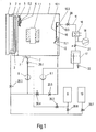
- the Drying device according to Fig.1 contains a vacuum-tight running container 1, which is equipped with a solid insulation containing electrical device, For example, a transformer, or - as shown - only with the Solid insulating containing active part 1.1 is loaded.
- the vacuum container 1 can be heated by means of heating pipes 2.
- the heating energy is in one Heat generator 3 on a flowing in the tubes 2 heat transfer medium for heating of the vacuum container 1 transmitted.
- the heating pipes 2 are of a double jacket surrounded and form together with the jacket a Solventerhitzer 4 a Solvent steam generator.
- the solvent heater cold solvent is heated.
- the solvent is generally a light oil with a much higher boiling point than water and a much lower boiling point than any in the Solid insulation existing insulating oil.
- the heated solvent is poured over an in 1 unsigned Solventitatisön in one within the Vacuum container 1 lying, optionally tubular, Solventverteilkanal 5 of Solventdampfer Wegers out.
- the solvent distribution channel 5 can with advantage as exposed pipe with injection openings and or Injectors are formed. This will be a cost effective device reached.
- the Solventverteilkanal 5 has injection openings or injectors for the solvent on.
- the straightening plate 6 can through Turning and / or moving in its position can be changed. This can be done the upstream of the nozzle throat of the Venturi nozzle located inflow and the downstream of the nozzle throat located Abströmquerites of Flow channel 5.2 enlarge or reduce.
- the vacuum container 1 has down in its bottom an opening into a drain tank 7 drain opening for condensed solvent on and optionally from the solvent from the Solid insulation washed out insulating oil.
- a Switch executed fill level indicator 7.1 arranged in the drain tank 7 .
- the drain tank 7 is via Shut-off valve 20.1 connected to a feed pump 8.
- the exit of the Feed pump 8 is connected via shut-off valve 20.3 with the Solventerhitzer 4 or alternatively via shut-off valve 20.6 with a solvent storage tank 9 or via Shut-off valve 20.7 with an oil tank 19 for receiving the optionally existing insulating oil, which during drying of the material to be dried 1.1 by the Solvent removed from the solid insulations and subsequently by distillation was separated from the solvent.
- the flow channel 5.2 is in the vacuum tank 1 a Condensation device arranged with a condensation chamber 10 for Heat recuperation, a baffle 10.1, baffles 10.2 and injectors 11.
- the condensation space 10 is down to the inside of the vacuum container. 1 open and has at its upper end a through the wall of the container. 1 guided outlet opening 10.3, which via a mixing steam line 15 and a Dampfabsperrventil 20 leads to a mixed steam condenser 16.
- the Mischdampfkondensator 16 has two outputs, one of which with a Vacuum system 18 and the other via a check valve 21 with a separation tank 17 is connected.
- the separation vessel 17 has two outputs, one of which on one of the removal of water serving discharge valve 22 acts and the other is connected to the input of a Solvent technicallypumpe 8.1 whose output optionally via a shut-off valve 20.5 to the injection nozzles 11, or over Shut-off valves 20.4 and 20.6 leads to the solvent reservoir tank 9.
- the heated solvent as intensive Solvent flow 5.3 from the Solventverteilkanal 5 in the flow channel 5.2 emerge and there with a solvent and water vapor containing Mixed steam from the interior of the container to a predominantly solvent vapor containing steam containing 5.4.
- the flow channel 5.2 can over the extend entire length and / or width of a wall of the container and possibly also consist of several short sections. Is the Solventverteilkanal as exposed pipe with injection openings or injectors trained, it is through the emerging from the manifold, expanding and partially evaporating solvent, the mixed steam in the flow channel on both sides of the Distributor pulled in over.
- the heating pipes 2 of the Solventerhitzers. 4 mainly oriented horizontally and that is the flow channel 5.2 limiting straightening plate 6 rotatably formed.
- the rotation of the straightening plate 6 can be achieved by a mechanical adjustment 6.2, which via a Lever gear on the pivotally mounted at a point 6.1 straightening plate 6 acts.
- the straightening plate between two positions 5.5 resp.
- the injected Solvent 14 and the condensed solvent vapor 14.1 flow to the drain pan 7 and be pumped with the feed pump 8, while remaining mixed steam 14.2 from the mixing steam flow 13 via the mixing steam line 15 from the Condensation space 10 is removed and led to a mixed steam condenser 16 becomes.
- the operation of the device is as follows: With the vacuum system 18, the vacuum container 1, the mixed steam condenser 16 and the separation tank 17 are evacuated. At the same time, the solvent supply tank 9 draws solvent via the shut-off valves 20.6 and 20.3 and the solvent heater 4 into the vacuum container 1 until the filling level indicator 7.1 is flooded.
- the solvent present in the vacuum tank 1 is circulated by the feed pump 8 and heated in the solvent heater 4 to a temperature slightly above a predetermined drying temperature. The heated solvent is heated to normal or possibly higher pressure.
- the pressure in the solvent 5.3 drops sharply and evaporates a portion of the heated solvent with simultaneous cooling by the amount of its heat of vaporization.
- the resulting solvent vapor 5.4 condenses on the active part and heats it with simultaneous evaporation of the water contained in the solid insulation, resulting in the formation of the solvent and steam containing mixed steam in the vacuum vessel 1.
- resulting and optionally insulating solvent-containing solvent condensate is fed back to the Solventverteilkanal 5 with the feed pump 8 via the solvent heater 4 for evaporation.
- the solvent 5.3 is advantageously injected at the nozzle throat via the injection openings 5.1 in the flow channel 5.2. This results in a particularly high flow velocity and a correspondingly high negative pressure. This leads to a jet effect, through which the mixed steam present in the vacuum tank 1 is sucked into the flow channel 5.2.
- the sucked mixed steam mixes with the injected solvent 5.3 and the solvent vapor 5.4 formed during injection.
- the injection nozzles 11, 11.1 is stored in the separation tank 17 cold solvent fed with the feed pump 8.1 via shut-off valve 20.5 and in the Condensation space 10 injected.
- the large surface of the injected cold solvent 14 condenses the solvent vapor component into the Condensation space 10 sucked mixed steam 13 to form the condensed solvent 14.1.
- This can be done in an advantageous manner Enrich water vapor in the condensation chamber 10. It will be less Solvent vapor led to the mixed steam condenser 16. It becomes so energy saved, which on the one hand for heating the solvent and the other to Cooling of the mixed steam condenser 16 is required.
- the injected solvent and the condensed solvent vapor flow over the drain tank 7 Feed pump 8 and are fed via shut-off valve 20.3 the solvent heater 4.
- the condensation chamber 10 with steam enriched solvent vapor is controlled by the Dampfabsperrventil 20 the mixed steam condenser 16th fed and condensed. This resulting air leakage is with the vacuum system 18th pumped out.
- the solvent and water-containing condensate is then by means of Sedimentation separated in the separation vessel 17 and the solvent with the pump 8.1 via Shut-off valve 20.5 fed back to the injectors 11, 11.1.
- the feed pump 8 is turned off and the Steam shut-off valve 20 fully open.
- condensation of solvent and Water vapor in the mixed steam condenser 16 is the pressure in the vacuum vessel. 1 lowered and at the same time accumulating in the separation tank 17 solvent condensate with the feed pump 8.1 via the valves 20.4, 20.6 supplied to the solvent reservoir tank 9.
- the shut-off valve 21 is closed and the Pressure in the vacuum container 1 with the vacuum pump 18 for a given Period lowered to low vacuum levels.
- the vacuum tank 1 is vented and then the dried material 1.1 is the Vacuum tank 1 removed.
- the Vacuum container 1 designed as a housing of a transformer, which is the Drying material, also in this case containing the solid insulation active part 1.1 of the transformer absorbs.
- the transformer housing 1 is in one réelleisolierhaus 1.5 arranged, which are heated by the heat generator 3 can.
- the heat generator 3 is designed as an air heater. The heating energy is supplied through the tubes 2. Through the tubes 2 heated air is used as a heat transfer medium with the help of a hot air fan 3.1 via a housing feedthrough 3.3 into Heat insulation house 1.5 transported. About a housing bushing 3.2 is air the heat insulating housing 1.5 back to the air heater and again heated.
- the Heating pipes 2 are surrounded by a double jacket and are from the heat generator. 3 heated both the transformer housing 1 and the solvent.
- the transformer housing. 1 but with cover flanges 1.3 vacuum-sealed openings 1.2, through which openings otherwise the power connections of the active part 1.1 are guided.
- one of these openings 1.2 is that of the Solventerhitzer 4 on the Solvent connection line 4.1 Flow channel supplied with hot solvent 5.2 arranged.
- the Solventdampfer Weger now one at the Nozzle throat of the venturi nozzle arranged and in the direction of the nozzle axis aligned injection nozzle 5.7, which via the line 4.1 with hot solvent is fed.
- Further solvent steam generators each with a flow channel and with one or possibly also with several injectors 5.7 can be provided other openings 1.2 of the transformer housing 1.
- the flow channel is 5.2 substantially formed axially symmetrical and is limited by a fixed and the large part around the axis bent Venturiblech 6.3 as well as by the adjustable executed straightening plate 6.
- Deflector 6.4 On the downstream side is on the straightening plate 6 in addition Deflector 6.4 arranged. By the sheet 6.4 is from the channel 5.2 passing, not evaporated solvent to the wall of the transformer housing. 1 guided and can quickly via a provided in the bottom drain port 1.4 ( Figure 6) removed again from the housing 1 and the solvent heater 4 are supplied.
- transformer housing 1 In a further opening 1.2 transformer housing 1 is the condensation chamber 10 arranged.
- Two embodiments of this condensation space are from the Figures 8 and 9 can be seen, wherein the embodiment of Figure 8 is largely the Embodiment corresponds to Figure 5 and the Fig.9 largely that according to Fig.4.
- the embodiment of Figure 8 is still an air-cooled Capacitor 23 shown, which with the outlet opening 10.3 of the Condensation space 10 connected via the line 15 and the Mixed steam condenser 16 to form an additional condensation stage for the enriched steam containing mixed steam 14.2 is connected upstream.
- Air heated in the air-cooled condenser 23 is transferred by a fan 23.1 an inlet opening 23.2 for heating purposes in the planteisoliergephase 1.4 transported.
- the drying device 6 shows the assembled transformer in the townisoliergephaseuse first are introduced and instead of housing bushings for the Power connections of the active part 1.1 for carrying the line 4.1 and the Injector 5.7 and to complete the condensation chamber 10 needed Connection flanges 1.3 mounted.
- Condensate drain is the Interior of the transformer housing 1 with the other components of the Drying device connected.
- the drying process can now - as in the embodiment the drying device according to Fig.1 described - be performed.
- the drying device in the vacuum tank 1 a generally as a cascade evaporator trained Solventdampfer Weger 24 arranged. Become this steam generator supplied from the outside through the wall of the vacuum vessel 1 solvent and heat. The amount of solvent supplied is by means of a Solventabsperrventils 20.9 controlled. The heat is placed in an outside of the vacuum tank Heat generator 24.2 formed. Solvent vapor 29 formed in the evaporator 24 flows through a solvent vapor outlet 24.1 in the flow channel 5.2.
- Reference numeral 25 is an outside of the vacuum container 1 befindaji Solvent heater, preheated in the solvent and the preheated Solvent via a Solventabsperrventil 20.8 dosed in the flow channel 5.2 located Solventverteilkanal 5 is performed. Injectors 5.7 of Solventverteilkanals 5 are arranged in the region of the bottleneck of the venturi.
- the preheated solvent 5.3 injected in the direction of the solvent vapor stream 29 sucks the Solventdampf from the evaporator 24 due to Jet Sign and so increases its flow velocity.
- the speed of the Flow channel 5.2 already increased mixed steam flow 30 increases.
- the from the Flow channel 5.2 passing steam flow 5.4 therefore has a high Flow rate and good turbulence. This results in a higher flow speed and better turbulence of the Vacuum vessel circulating solvent vapor stream than conventional Method.
- the drying times are at the same time low Energy consumption reduced.
- the Jet Angel remains the desired high Solvent vapor velocity in the autoclave towards the end of the heating phase receive. This leads to a shorter heating time in the upper temperature range and Accordingly, also provides a small temperature difference over the Drying 1.1 and thus an improved drying quality safely.
- Solvent evaporator 26 for example, a large evaporator or a Downpipe evaporator
- the Jet Sign of injected in the direction of the steam flow 29 heated Solvents are analogous to the embodiment according to FIG. 10 of the solvent vapor the steam line and the mixed steam are sucked out of the autoclave 1 and become so the flow velocity and the turbulence of the steam flow in 5.4 advantageously increased.
Landscapes
- Engineering & Computer Science (AREA)
- Mechanical Engineering (AREA)
- General Engineering & Computer Science (AREA)
- Health & Medical Sciences (AREA)
- Life Sciences & Earth Sciences (AREA)
- Molecular Biology (AREA)
- Drying Of Solid Materials (AREA)
Abstract
Das Verfahren dient der Trocknung eines Gutes (1.1), vorzugsweise der Feststoffisolationen eines elektrischen Gerätes, nach der Vapour - Phase - Methode. Bei diesem Verfahren wird das zumindest Wasser, gegebenenfalls zusätzlich Isolieröl sowie Verunreinigungen enthaltende Gut (1.1) in einem Vakuumbehälter (1) bei Unterdruck durch Kondensation von Solventdampf (5.4) aufgeheizt. Ein hierbei gebildeter zumindest Solvent- und Wasserdampf enthaltender Mischdampfstrom wird nachfolgend kondensiert und aus dem Kondensat Wasser und Solvent abgetrennt. Der Solventdampf (5.4) wird von Solvent gebildet, welches bei einem Druck erwärmt wird, der über dem im Vakuumbehälter (1) herrschenden Druck liegt. Um den Energieverbrauch und die Durchlaufzeit des Verfahrens gering zu halten, wird das erwärmte Solvent (5.3) in einen im Inneren des Vakuumbehälters (1) angeordneten und nach Art einer Venturidüse ausgebildeten Strömungskanal (5.2) eingespritzt. Eine besonders hohe Effizienz weist das Verfahren dann auf, wenn das erwärmte Solvent (5.3) in einen in der Venturidüse geführten Solventdampfstrom (29) eingespritzt wird. <IMAGE>The method is used to dry a product (1.1), preferably the solid insulation of an electrical appliance, according to the vapor phase method. In this method, the at least water, optionally in addition insulating oil and impurities containing Good (1.1) in a vacuum vessel (1) is heated at reduced pressure by condensation of solvent vapor (5.4). A mixed steam stream containing at least solvent and water vapor is subsequently condensed and water and solvent are separated from the condensate. The solvent vapor (5.4) is formed by solvent, which is heated at a pressure which is above the pressure prevailing in the vacuum container (1). In order to keep the energy consumption and the throughput time of the process low, the heated solvent (5.3) is injected into a flow channel (5.2) arranged in the interior of the vacuum container (1) and designed in the manner of a Venturi nozzle. The process has a particularly high efficiency when the heated solvent (5.3) is injected into a solvent vapor stream (29) guided in the venturi nozzle. <IMAGE>
Description
Bei der Erfindung wird ausgegangen von einem Verfahren zur Trocknung von Gut,
wie insbesondere von Feststoffisolationen eines elektrischen Geräts, nach dem
Oberbegriff von Patentanspruch 1. Die Erfindung betrifft zugleich auch eine
Vorrichtung zur Durchführung des Verfahrens.The invention is based on a process for drying good,
in particular solid insulation of an electrical appliance, according to
The preamble of
Bei dem Verfahren wird die Kondensationswärme eines in einem Verdampfer erzeugten Solventdampfs zum raschen und schonenden Aufheizen des Guts ausgenutzt. Das Trocknungsgut umfasst im allgemeinen die Feststoffisolationen eines elektrischen Gerätes, etwa eines Leistungstransformators. Das Gerät oder zumindest dessen die Feststoffisolationen enthaltendes Aktivteil sind in einem auf Unterdruck gehaltenen Vakuumbehälter, beispielsweise einem Autoklaven, angeordnet. Beim Aufheizen aus den Feststoffisolationen austretendes Wasser wird in Form eines Solvent- und Wasserdampf enthaltenden Mischdampfs zusammen mit nicht zu vermeidender Leckluft einer Kondensations- und Trennvorrichtung zugeführt, in der das kondensierte Wasser vom Solvent getrennt und die Leckluft mit einer Vakuumpumpe abgesaugt wird. Gegebenfalls vorhandenes Isolieröl und/oder Verunreinigungen werden durch Destillation aus dem Solvent entfernt. Bei der Ausführung dieses sogenannten Vapour-Phase-Verfahrens fallen folgende Prozess-Schritte an:
- Beladen des Autoklaven mit Gut,
- Evakuieren des beladenen Autoklaven,
- Aufheizen des beladenen Autoklaven mit kondensierendem Solventdampf und gegebenenfalls zusätzlich mit der Autoklavheizung, um den überwiegenden Teil des Wasser sowie des gegebenenfalls vorhandenen Isolieröls und der Verunreinigungen aus dem Gut zu entfernen,
- Durchführen von Zwischendrucksenkungen im Autoklaven, um während des Aufheizens ausgewaschenes Isolieröl abzudestillieren und um in besonders schneller und schonender Weise die vorgenannten Substanzen zu entfernen,
- Anlegen von Feinvakuum bei eingeschalteter Autoklavheizung an den Autoklaven, um noch vorhanden Restsubstanzen aus den Feststoffisolationen zu entfernen, und
- Belüften und Entladen des Autoklaven.
- Loading the autoclave with good,
- Evacuating the loaded autoclave,
- Heating the loaded autoclave with condensing solvent vapor and possibly also with the autoclave heater, in order to remove most of the water and the optionally existing insulating oil and impurities from the estate,
- Carrying out intermediate pressure reductions in the autoclave in order to distil off washed-out insulating oil during the heating and to remove the abovementioned substances in a particularly rapid and gentle manner,
- Apply fine vacuum with the autoclave heating switched on to the autoclave to remove residual substances from the solid insulation, and
- Aerating and unloading the autoclave.
Das Verfahren der eingangs erwähnten Art ist DE 30 14 831 A entnehmbar. Eine in
diesem Stand der Technik beschriebene, nach dem Vapour-Phase-Verfahren
arbeitende Trocknungsvorrichtung für isolierölgetränkte Isolierungen weist einen die
zu trocknenden Isolierungen aufnehmenden evakuierbaren Autoklaven auf, in dem
ein Kaskadenverdampfer angeordnet ist. Dieser Kaskadenverdampfer ist im
wesentlichen vertikal ausgerichtet und enthält einen von einer Platte und einer
Trennwand begrenzten Strömungskanal. An der Platte sind Heizschlangen und
Leitbleche angeordnet. Dem Kaskadenverdampfer wird mittels einer Pumpe Solvent
zugeführt, welches in einem ausserhalb des Autoklaven angeordneten Vorwärmer
erwärmt wurde. Das vorgewärmte Solvent rieselt unter Mitwirkung der Leitbleche
längs der Platte von oben nach unten. Hierbei verdampft das Solvent an den
Heizschlangen. Der sich bildende Solventdampf strömt aufgrund von Kaminwirkung
im Strömungskanal vertikal nach oben und wird über einen Dampfeintritt in den die
Isolierungen enthaltenden Nutzraum des Autoklaven geführt.The method of the type mentioned is
Ein weiteres Trocknungsverfahren wurde in den USA durch die Firmen "General Electric" und "Westinghouse" ab ca. 1960 appliziert. Dabei wurde das Solvent in einem ausserhalb des Autoklaven liegenden Solventerhitzer aufgeheizt und in den unter Vakuum stehenden Autoklaven eingeführt und dabei verdampft, wie im Buch "A Guide to Transformer Maintenance" von S.D.Meyers, J.J.Kelly, P.H.Parish, S.496 (Transformer Maintenance Institute, Division, S.D.Myers, Inc. Akron Ohio, 1981) erwähnt. Hierbei wird das Solvent wesentlich über die Trocknungstemperatur aufgeheizt, da dem Solvent Verdampfungswärme entzogen wird und sich dabei abkühlt. Eine genaue Temperaturkontrolle des Solventdampfs ist schwierig, da diverse Faktoren wie Druck und Temperatur im Autoklaven die Verdampfungsrate und somit auch die Solventdampftemperatur beeinflussen.Another drying process was in the US by the company "General Electric "and" Westinghouse "applied from about 1960. The solvent was in heated outside the autoclave solvent heater and in the introduced under vacuum autoclave and thereby evaporated, as in the book "A Guide to Transformer Maintenance "by S.D.Meyers, J.J. Kelly, P.H.Parish, p.496 (Transformer Maintenance Institute, Division, S.D.Myers, Inc. Akron Ohio, 1981) mentioned. Here, the solvent is significantly above the drying temperature heated, as the solvent evaporation heat is withdrawn and thereby cools. Accurate temperature control of the solvent vapor is difficult since various factors such as pressure and temperature in the autoclave the evaporation rate and thus also influence the solvent vapor temperature.
Das vorgenannte Trockenverfahren ist auch beschrieben in US 2002/0184784 A1. Bei diesem Stand der Technik wird Heizflüssigkeit in der flüssigen Phase belassend ausserhalb eines Trockengut enthaltenden Vakuumgefässes erhitzt. Nachfolgend wird die erhitzte Heizflüssigkeit am oder im Vakuumgefäss verdampft.The aforementioned dry process is also described in US 2002/0184784 A1. In this prior art, heating fluid is left in the liquid phase heated outside a drying vessel containing vacuum vessel. following the heated heating fluid is evaporated on or in a vacuum vessel.
In der Firmenschrift P.K.Gmeiner "Modern vapour drying processes and plants", Februar 1992, Micafil Vakuumtechnik AG, Zürich MTV/E 0293000/22 sind nach der Vapour-Phase-Methode arbeitende Solventdampftrocknungsanlagen mit separaten, ausserhalb oder innerhalb eines Autoklaven liegenden Solventverdampfern beschrieben. Alle die zur Ausführung der beschriebenen Verfahren eingesetzten Vorrichtungen, bedingen eine Autoklavheizung und zusätzlich einen Verdampfer mit einer komplexen Temperatursteuerung zur Regelung des Solventdampfs mit hoher Genauigkeit zu regulieren.In the publication P.K.Gmeiner "Modern vapor drying processes and plants", February 1992, Micafil Vakuumtechnik AG, Zurich MTV / E 0293000/22 are after the Vapour phase method working solvent steam drying plants with separate, outside or inside an autoclave solvent evaporators described. All those used to carry out the described methods Devices, require a autoclave heater and in addition an evaporator a complex temperature control for controlling the solvent vapor with high To regulate accuracy.
Die Trocknung von Transformatoren im eigenen Gehäuse statt in einem als Autoklav ausgeführten vakuumfesten Behälter wird seit ca.1975 appliziert. Dabei wird das Solvent in einem ausserhalb des Transformators liegendem Solventverdampfer verdampft und über grosse und lange flexible Leitungen in das evakuierte Transformatorgehäuse gebracht, wie dies in der Firmenschrift G.Oesch, H.Schatzl, "Die Solventdampftrocknung von Leistungstransformatoren" August 1976, Micafil AG, 8048 Zürich/Schweiz (Bestell-Nr. MNV 46/1 d) beschrieben ist.The drying of transformers in their own housing instead of in an autoclave executed vacuum-resistant container is applied since ca.1975. This is the Solvent in a solvent evaporator outside the transformer evaporated and over large and long flexible lines in the evacuated Transformer housing brought, as in the company G.Oesch, H. Schatzl, "Solvent vapor drying of power transformers" August 1976, Micafil AG, 8048 Zurich / Switzerland (order number MNV 46/1 d).
Der vorliegenden Erfindung liegt die Aufgabe zu Grunde, den Energieverbrauch und die Durchlaufzeit des Verfahrens der eingangs genannten Art zu reduzieren und zugleich Vorrichtungen anzugeben, welche in besonders vorteilhafter Weise zur Durchführung dieses Verfahren geeignet sind. The present invention is based on the object, the energy consumption and to reduce the lead time of the method of the type mentioned above and at the same time provide devices which in a particularly advantageous manner to Implementation of this method are suitable.
Beim erfindungsgemässen Verfahren wird das in den Vakuumbehälter geführte und erwärmte Solvent in einen nach Art einer Venturidüse ausgebildeten Strömungskanal eingespritzt. Dabei wird ein überwiegend Solventdampf enthaltender und durch eine Engstelle des Strömungskanal geführter Strahl gebildet, welcher sich infolge Saugwirkung intensiv mit einem bereits im Vakuumbehälter vorhandenen Anteil an Solventdampf mischt. Je nach Anteil und oder Menge an zugemischtem Mischdampf, sowie nach Menge des eingespritzten heissen Solvents kann die Temperatur des aus dem Strömungskanal tretenden Solventdampfes sehr genau gesteuert werden. Zugleich ist durch die durch den Strahl angeregte Strömung eine optimale Umwälzung und Turbulenz des Solventdampfes im Vakuumbehälter sichergestellt. Hierdurch werden die zum Aufheizen des Trocknungsguts benötigte Energiemenge und die Aufheizzeit stark reduziert. Die Reduktion der Aufheizzeit ist vor allem auch dadurch bedingt, dass durch starkes während der gesamten Aufheizphase praktisch konstantes Einspritzen von aufgeheiztem Solvent in den Strömungskanal eine grosse Umwälzmenge an Solventdampf und somit eine hohe Solventdampfgeschwindigkeit auch gegen Ende der Aufheizphase im Vakuumbehälter erhalten bleibt. Trotz des geringen Energieverbrauchs und der kurzen Durchlaufzeit benötigt das Verfahren über die bei herkömmlichen Verfahren notwendigen Komponenten hinaus keine aufwendigen Zusatzkomponenten.In the inventive method, the guided in the vacuum tank and heated solvent in a formed in the manner of a venturi flow channel injected. In this case, a predominantly solvent vapor-containing and by a Constriction of the flow channel guided beam formed, which is due to Suction intense with an already existing in the vacuum container share Solvent vapor mixes. Depending on the proportion and or amount of mixed steam mixed in, as well as the amount of injected hot solvent, the temperature of the From the flow channel passing solvent vapor can be controlled very precisely. At the same time, the flow stimulated by the jet is an optimal one Circulation and turbulence of the solvent vapor in the vacuum tank ensured. As a result, the amount of energy required to heat the drying material and greatly reduces the heating time. The reduction of the heating time is above all due to the fact that strong during the entire heating phase practically constant injection of heated solvent into the flow channel one large circulation of solvent vapor and thus a high Solvent vapor velocity also towards the end of the heating phase in the Vacuum tank is maintained. Despite the low energy consumption and the short cycle time required the process over that in conventional methods necessary components addition no complex additional components.
Eine besonders kurze Durchlaufzeit wird erreicht, wenn das erwärmte Solvent in einen durch die Venturidüse geführten Solventdampfstrom eingespritzt wird. Infolge der Jetwirkung des eingespritzten Solvents werden die Geschwindigkeit und die Turbulenzen des in der Venturidüse geführten Solventdampfstroms wesentlich erhöht. Hieraus resultieren eine hohe Geschwindigkeit und eine gute Turbulenz des im Vakuumbehälter zirkulierenden Solventdampfes und wird dementsprechend die Trockenzeit stark verringert. Die erhöhte Solventdampfgeschwindigkeit wird infolge der Jetwirkung ebenfalls gegen Ende der Aufheizphase aufrechterhalten, was eine kürzere Aufheizzeit im oberen Temperaturbereich und eine noch kleinere Temperaturdifferenz über das Trocknungsobjekt sicherstellt, wodurch die Güte der Trocknung erheblich verbessert wird.A particularly short cycle time is achieved when the heated solvent in injected through the venturi solvent vapor stream is injected. As a result The effect of the injected solvent will be the speed and the Turbulence of the guided in the Venturi nozzle solvent vapor stream substantially elevated. This results in a high speed and good turbulence of the In the vacuum vessel circulating solvent vapor and is accordingly the Drying time greatly reduced. The increased solvent vapor velocity is due the Jetwirkung also maintained towards the end of the heating phase, which is a shorter heating time in the upper temperature range and even smaller Temperature difference across the drying object ensures, reducing the quality of the Drying is significantly improved.
Vorteilhafterweise wird der vorgenannte in der Venturidüse geführte Solventdampfstrom in einem im Vakuumbehälter angeordneten Verdampfer erzeugt, da dann nämlich durch die Jetwirkung des eingespritzten Solvents der vom Verdampfer erzeugte Solventdampf rasch vom Verdampfer weggesaugt wird, was zu kleinerem Druckverlust in diesem Verdampfer und somit zu erhöhter Effizienz führt.Advantageously, the aforementioned is guided in the Venturi nozzle Generates solvent vapor stream in a vacuum vessel arranged in the evaporator, because then by the action of the injected solvent of the Evaporator generated solvent vapor is rapidly sucked away from the evaporator, resulting in smaller pressure loss in this evaporator and thus leads to increased efficiency.
Der Solventdampfstrom kann auch in einem ausserhalb des Vakuumbehälters angeordneten Verdampfer erzeugt und durch die Wand ins Innere des Vakuumbehälters geführt werden. Infolge der Jetwirkung wird dann der Solventdampf besser aus einer in den Vakuumbehälter geführten Solventdampfleitung abgesaugt, was zu kleinerem Druckverlust zwischen externem Verdampfer und Vakuumbehälter und somit ebenfalls zu erhöhter Effizienz führt.The solvent vapor stream can also be in an outside of the vacuum vessel arranged evaporator generated and through the wall into the interior of the Vacuum container are guided. As a result of the Jetwirkung then the Solvent vapor better from a guided in the vacuum tank Solvent vapor line sucked, resulting in smaller pressure drop between external Evaporator and vacuum vessel and thus also leads to increased efficiency.
Mit Vorteil wird das erwärmte Solvent an der Engstelle der Venturidüse in den Strömungskanal eingespritzt. An der Engstelle weist das in den Strömungskanal eingespritzte Solvent besonders hohe Geschwindigkeit auf. Diese hohe Geschwindigkeit ruft einen grossen Unterdruck und damit eine starke Jet-Wirkung hervor, d.h. ein besonders starkes Einsaugen eines im Vakuumbehälter beim Aufheizen des Trocknungsguts gebildeten Mischdampfstroms aus Solvent- und Wasserdampf in das eingespritzte Solvent.Advantageously, the heated solvent at the bottleneck of the Venturi nozzle in the Injected flow channel. At the bottleneck, this points into the flow channel injected solvent particularly high speed up. This high Speed calls for a great vacuum and thus a strong jet effect out, i. a particularly strong sucking a in the vacuum container when Heating the drying material formed mixed steam flow of solvent and Water vapor in the injected solvent.
Durch Veränderung von Zuström- und/oder Abströmquerschnitt des Strömungskanals kann auch das Mischungsverhältnis von eingespritztem heissem Solvent zu dem im Vakuumbehälter bereits strömenden Mischdampf verändert werden. Es kann damit auch die Temperatur des aus dem Strömungskanal tretenden Solventdampfstroms mit grosser Geschwindigkeit und guter Genauigkeit gesteuert werden.By changing the inflow and / or outflow cross section of the Flow channel can also the mixing ratio of injected hot Solvent changed to the already flowing in the vacuum tank mixed steam become. It can thus also the temperature of passing from the flow channel Solvent vapor flow controlled at high speed and with good accuracy become.
Das erfindungsgemässe Verfahren zeichnet sich durch einen besonders hohen Wirkungsgrad aus, wenn in den im Inneren des Vakuumbehälters geführten Mischdampfstrom kaltes Solvent eingespritzt wird. Durch Einspritzen von kaltem Solvent, etwa in einen im Vakuumbehälter angeordneten Kondensationsraums, wird ein Teil des im Mischdampf vorhandenen Solventdampfs durch Jet-Wirkung angesaugt und kondensiert. Dadurch steigt der Anteil des Wasserdampfes im Kondensationsraum an und demzufolge muss weniger Solventdampf in einem ausserhalb des Vakuumbehälters liegenden Kondensator als Kondensat abgeschieden werden, wodurch der Energiebedarf des Verfahrens zusätzlich reduziert wird. Wird das kalte Solvent in Strömungsrichtung in den Mischdampfstrom eingespritzt, so wird wegen der Strahlwirkung der Mischdampf stark angesaugt und infolge intensiver Mischung eine hohe Wärmerekuperation durch Aufheizen des eingespritzten kalten Solvents erreicht.The inventive method is characterized by a particularly high Efficiency, when in the guided inside the vacuum tank Mixed steam flow cold solvent is injected. By injecting cold Solvent, such as in a vacuum container arranged in the condensation space, is a portion of the solvent vapor present in the mixed steam by jet action sucked in and condensed. This increases the proportion of water vapor in the Condensation on and consequently has less solvent vapor in one outside the vacuum tank condenser as condensate be deposited, whereby the energy requirement of the process in addition is reduced. If the cold solvent in the flow direction in the mixed steam flow injected, so the mixed steam is strongly sucked because of the blasting effect and due to intensive mixing a high heat recuperation by heating the achieved injected cold solvent.
Eine weitere Verringerung des Energiebedarfs des erfindungemässen Verfahrens wird dadurch erreicht, dass der Mischdampfstrom aus dem Vakuumbehälter geführt und ausserhalb des Behälters in zwei oder mehr Stufen kondensiert wird, und dass mit der in einer ersten der Stufen beim Kondensieren von Mischdampf abgegebenen Kondensationswärme Heizluft erwärmt wird.A further reduction of the energy requirement of erfindungemässen method is achieved in that the mixed steam flow out of the vacuum tank and condensed outside the container in two or more stages, and that with the output in a first of the stages in the condensing of mixed steam Condensation heat heating air is heated.
Bei einer zur Durchführung des erfindungsgemässen Verfahrens in einfacher und wirtschaftlicher Weise geeigneten Vorrichtung, welche neben dem Vakuumbehälter auch einen Solventdampferzeuger und eine Vorrichtung zum Kondensieren des Mischdampfstroms aufweist, enthält der Solventdampferzeuger einen im Inneren des Vakuumbehälters angeordneten und nach Art einer Venturidüse ausgebildeten Strömungskanal sowie eine in den Strömungskanal geführte Vorrichtung zum Einspritzen von erwärmtem Solvent in den Strömungskanal. Durch eine besonders gute Wirkungsweise zeichnet sich diese Vorrichtung dann aus, wenn die Einspritzvorrichtung an der Engstelle der Venturidüse in den Strömungskanal mündet. Besonders zweckmässige Ausbildungen der Einspritzvorrichtung enthalten einen mit Einspritzöffnungen in den Strömungskanal mündenden Solventverteilkanal und/oder mindestens eine im Inneren des Strömungskanals gehaltene Einspritzdüse.In a for carrying out the inventive method in simple and economically suitable device, which in addition to the vacuum tank also a solvent steam generator and a device for condensing the Having mixed steam flow, the solvent steam generator contains a inside the Vacuum container arranged and designed in the manner of a Venturi nozzle Flow channel and a guided in the flow channel device for Injecting heated solvent into the flow channel. By a particularly good mode of action, this device is characterized when the Injection device at the bottleneck of the Venturi nozzle in the flow channel empties. Include particularly expedient embodiments of the injection device an opening with injection openings in the flow channel Solventverteilkanal and / or at least one held in the interior of the flow channel injection nozzle.
Heizenergie kann eingespart und damit der Wirkungsgrad des Verfahrens weiter verbessert werden, wenn die zum Heizen des Vakuumbehälters vorgesehene Heizvorrichtung als Durchlauferhitzer für das Solvent ausgeführt ist.Heating energy can be saved and thus the efficiency of the process on be improved if provided for heating the vacuum tank Heating device is designed as a water heater for the solvent.
Eine einfache Regelung von Temperatur und Mischungsverhältnis des aus dem Strömungskanal austretenden Solventdampfs kann dadurch erreicht werden, dass ein den Strömungskanal begrenzendes Richtblech unter Veränderung des Zuströmund/oder Abströmquerschnitts des Strömungskanals verstellbar ausgebildet ist. A simple control of temperature and mixing ratio of the Flow channel escaping solvent vapor can be achieved in that a directional channel limiting the flow channel, changing the inflow and / or Outflow cross section of the flow channel is adjustable.
Viel Heizenergie wird dadurch eingespart, dass im Vakuumbehälter ein mindestens eine Einspritzdüse für kaltes Solvent aufnehmender und vom Mischgas durchströmter Kondensationsraum der Kondensationsvorrichtung angeordnet ist. Mit Vorteil ist dieser Kondensationsraum als Strömungskanal für das Mischgas ausgebildet und weist einströmseitig ein als Zuströmkanal einer Venturidüse wirkendes Blech auf und/oder ein Abflussblech und/oder abströmseitig ein Umlenkblech.Much heating energy is saved by the fact that in the vacuum tank at least an injector for cold solvent receiving and from the mixed gas flowed through the condensation chamber of the condensation device is arranged. With Advantage is this condensation space as a flow channel for the mixed gas formed and has inflow as an inflow channel of a venturi acting sheet on and / or a drain sheet and / or downstream Baffle.
Die benötigte Heizenergie wird zusätzlich dadurch verringert, dass die Kondensationsvorrichtung einen ausserhalb des Vakuumbehälters angeordneten, luftgekühlten Kondensator zur Erzeugung von Heizluft aufweist.The required heating energy is additionally reduced by the fact that the Condensing device arranged outside the vacuum container, having air-cooled condenser for generating heating air.
In einer weiteren bevorzugten Ausführungsform der erfindungsgemässen Trocknungsvorrichtung ist der Vakuumbehälter als Gehäuse eines Transformators ausgeführt und in einem vorzugsweise mit Luft heizbaren Wärmeisolierhaus angeordnet.In a further preferred embodiment of the inventive Drying device is the vacuum container as a housing of a transformer executed and in a preferably heatable with air Wärmeisolierhaus arranged.
Bevorzugte Ausführungsformen der Erfindung werden anhand der beigefügten Zeichnungen beschrieben. Hierbei zeigt:
- Fig.1
- eine Trocknungsvorrichtung nach der Erfindung, enthaltend einen geschnitten dargestellten, Feststoffisolationen eines Transformators als Trocknungsgut aufnehmenden Vakuumbehälter, einen Solventdampferzeuger zum Aufheizen, Zuführen und Verteilen von Solvent und zum Erzeugen von Solventdampf und einen Vorrichtung zum Kondensieren von Solventdampf,
- Fig.2
- eine erste Ausführungsform des in der Trocknungsvorrichtung nach Fig.1 enthaltenen Solventdampferzeugers,
- Fig.3
- eine zweite Ausführungsform des in der Trocknungsvorrichtung nach Fig.1 enthaltenen Solventdampferzeugers,
- Fig.4
- eine erste Ausführungsform der in der Trocknungsvorrichtung nach Fig.1 enthaltenen Kondensationsvorrichtung,
- Fig.5
- eine zweite Ausführungsform der in der Trocknungsvorrichtung nach Fig.1 enthaltenen Kondensationsvorrichtung,
- Fig.6
- eine abgewandelte Ausführungsform der Trocknungsvorrichtung nach Fig.1, bei der der Vakuumbehälter vom Gehäuse eines Transformators gebildet ist,
- Fig.7
- eine Ausführungsform des in der Trocknungsvorrichtung nach Fig.6 enthaltenen Solventdampferzeugers,
- Fig.8
- eine erste Ausführungsform der in der Trocknungsvorrichtung nach Fig.6 enthaltenen Kondensationsvorrichtung,
- Fig.9
- eine zweite Ausführungsform der in der Trocknungsvorrichtung nach Fig.6 enthaltenen Kondensationsvorrichtung,
- Fig.10
- eine abgewandelte Ausführungsform der Trocknungsvorrichtung nach Fig.1, bei der im Vakuumbehälter zusätzlich ein weiterer Solventverdampfer angeordnet ist, und
- Fig.11
- eine abgewandelte Ausführungsform der Trocknungsvorrichtung nach Fig.1, bei der dem Vakuumbehälter Solventverdampf zuführbar ist, der ausserhalb des Vakuumbehälters erzeugt werden kann.
- Fig.1
- a drying device according to the invention, comprising a cut-off solid insulation of a transformer as a vacuum-receiving vacuum vessel, a solvent steam generator for heating, supplying and distributing solvent and for generating solvent vapor and a device for condensing solvent vapor,
- Fig.2
- a first embodiment of the solvent steam generator contained in the drying apparatus according to Figure 1,
- Figure 3
- a second embodiment of the solvent steam generator contained in the drying apparatus according to Figure 1,
- Figure 4
- a first embodiment of the condensation device contained in the drying apparatus according to Figure 1,
- Figure 5
- a second embodiment of the condensation device contained in the drying apparatus according to Figure 1,
- Figure 6
- a modified embodiment of the drying device according to Figure 1, wherein the vacuum container is formed by the housing of a transformer,
- Figure 7
- an embodiment of the solvent steam generator contained in the drying device according to Figure 6,
- Figure 8
- a first embodiment of the condensation device contained in the drying device according to Figure 6,
- Figure 9
- a second embodiment of the condensation device contained in the drying device according to Figure 6,
- Figure 10
- a modified embodiment of the drying apparatus according to Figure 1, wherein in the vacuum container in addition a further solvent evaporator is arranged, and
- Figure 11
- a modified embodiment of the drying apparatus according to Figure 1, in which the vacuum vessel solvent evaporation can be supplied, which can be generated outside the vacuum vessel.
In allen Figuren bezeichnen gleiche Bezugszeichen auch gleichwirkende Teile. Die in
den Figuren dargestellten Trocknungsvorrichtungen dienen dem Trocknen von Gut,
insbesondere der Feststoffisolationen eines oder mehrerer elektrischer Geräte sowie
dem Entfernen von möglicherweise in den Isolationen vorhandenem Isolieröl. Die
Trocknungsvorrichtung nach Fig.1 enthält einen vakuumdicht ausgeführten Behälter
1, welcher mit einem Feststoffisolationen enthaltenden elektrischen Gerät,
beispielsweise einem Transformator, oder - wie dargestellt - auch nur mit dessen die
Feststoffisolationen enthaltendem Aktivteil 1.1 beladen ist. Der Vakuumbehälter 1
kann mit Hilfe von Heizrohren 2 beheizt werden. Die Heizenergie wird in einem
Wärmeerzeuger 3 auf einen in den Rohren 2 fliessenden Wärmeträger zum Heizen
des Vakuumbehälters 1 übertragen. Die Heizrohre 2 sind von einem Doppelmantel
umgeben und bilden zusammen mit dem Mantel einen Solventerhitzer 4 eines
Solventdampferzeugers. Im Solventerhitzer wird kaltes Solvent erhitzt. Das Solvent
ist im allgemeinen ein Leichtöl mit einem wesentlich höheren Siedepunkt als Wasser
und einem wesentlich niedrigeren Siedepunkt als ein gegebenenfalls in den
Feststoffisolationen vorhandenes Isolieröl. Das erhitzte Solvent wird über eine in
Fig.1 nicht bezeichnete Solventverbindungsleitung in einen innerhalb des
Vakuumbehälters 1 liegenden, gegebenenfalls rohrförmig ausgebildeten,
Solventverteilkanal 5 des Solventdampferzeugers geführt. Der Solventverteilkanal 5
kann mit Vorteil als freiliegendes Rohr mit Einspritzöffnungen und oder
Einspritzdüsen ausgebildet werden. Dadurch wird eine kostengünstige Vorrichtung
erreicht. Der Solventverteilkanal 5 weist Einspritzöffnungen oder Einspritzdüsen für
das Solvent auf. Im Bereich der Einspritzöffnungen liegt der engste Querschnitt eines
nach Art einer Venturidüse ausgeführten Strömungskanals 5.2, welcher durch ein
geeignet gebogenes Richtblech 6, eine Aussenwand des Solventverteilkanals 5 und
die Wand des Vakuumbehälters 1 gebildet wird. Das Richtblech 6 kann durch
Drehen und/oder Verschieben in seiner Lage verändert werden. Dadurch lassen sich
der stromauf der Düsenengstelle der Venturidüse befindliche Zuströmquerschnitt und
der stromab der Düsenengstelle befindliche Abströmquerschnitt des
Strömungskanals 5.2 vergrössern oder verkleinern. Der Vakuumbehälter 1 weist
unten in seinem Boden eine in einen Ablaufbehälter 7 einmündende Ablauföffnung
für kondensiertes Solvent auf sowie für gegebenenfalls vom Solvent aus den
Feststoffisolationen ausgewaschenes Isolieröl. Im Ablaufbehälter 7 ist ein als
Schalter ausgeführter Füllstandsindikator 7.1 angeordnet. Der Ablaufbehälter 7 ist via
Absperrventil 20.1 mit einer Förderpumpe 8 verbunden. Der Austritt der
Förderpumpe 8 ist via Absperrventil 20.3 mit dem Solventerhitzer 4 verbunden oder
alternativ via Absperrventil 20.6 mit einem Solventvorratstank 9 oder via
Absperrventil 20.7 mit einem Öltank 19 zur Aufnahme des gegebenenfalls
vorhandenen Isolieröls, welches beim Trocknen des Trocknungsgutes 1.1 durch das
Solvent aus den Feststoffisolationen herausgelöst und nachfolgend durch Destillation
vom Solvent abgetrennt wurde.In all figures, like reference numerals designate like-acting parts. In the
The drying devices shown in the figures serve to dry good,
in particular the solid insulation of one or more electrical devices as well
removing any insulating oil that may be present in the insulation. The
Drying device according to Fig.1 contains a vacuum-
Gegenüber dem Strömungskanal 5.2 ist im Vakuumbehälter 1 eine
Kondensationsvorrichtung angeordnet mit einem Kondensationsraum 10 zur
Wärmerekuperation, einem Leitblech 10.1, Umlenkblechen 10.2 und Einspritzdüsen
11. Der Kondensationsraum 10 ist nach unten zum Inneren des Vakuumbehälters 1
hin geöffnet und weist an seinem oberen Ende eine durch die Wand des Behälters 1
geführte Austrittsöffnung 10.3 auf, welche über eine Mischdampfleitung 15 und ein
Dampfabsperrventil 20 zu einem Mischdampfkondensator 16 führt. Der
Mischdampfkondensator 16 weist zwei Ausgänge auf, von denen einer mit einer
Vakuumanlage 18 und der andere über ein Absperrventil 21 mit einem Trennbehälter
17 verbunden ist. Der Trennbehälter 17 weist zwei Ausgänge auf, von denen einer
auf ein der Entnahme von Wasser dienendes Ablassventil 22 wirkt und der andere
mit dem Eingang einer Solventförderpumpe 8.1 verbunden ist, deren Ausgang
wahlweise über ein Absperrventil 20.5 zu den Einspritzdüsen 11, oder über
Absperrventile 20.4 und 20.6 zum Solventvorratstank 9 führt.Opposite the flow channel 5.2 is in the vacuum tank 1 a
Condensation device arranged with a
Der Aufbau zweier Ausführungsformen des in der Trocknungsvorrichtung nach Fig.1
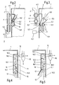
vorgesehenen Solventdampferzeugers ist aus den Figuren 2 und 3 ersichtlich. Bei
der Ausführungsform nach Fig.2 weist der Solventerhitzer 4 des
Solventdampferzeugers vertikal ausgerichtete Heizrohre 2 auf. Ersichtlich wird das
kalte Solvent mit Hilfe einer Zuführleitung 4.2 am unteren Ende in den
Solventerhitzer 4 geführt und dort erwärmt. Am oberen Ende des Solventerhitzers 4
wird erwärmtes Solvent über die die vorstehend bereits genannte und nun mit dem
Bezugszeichen 4.1 gekennzeichnete Solventverbindungsleitung durch die Wand des
Vakuumbehälters 1 in den im Behälterinneren angeordneten Solventverteilkanal 5
geführt. Durch die vorstehend bereits genannten und nun mit dem Bezugszeichen
5.1 gekennzeichneten Einspritzöffnungen kann das erwärmte Solvent als intensive
Solventströmung 5.3 aus dem Solventverteilkanal 5 in den Strömungskanal 5.2
austreten und sich dort mit einem Solvent- und Wasserdampf enthaltendem
Mischdampf aus dem Behälterinneren zu einem überwiegend Solventdampf
enthaltenden Dampf 5.4 vereinigen. Der Strömungskanal 5.2 kann sich über die
gesamte Länge und/oder Breite einer Wand des Behälters erstrecken und
gegebenenfalls auch aus mehreren kurzen Abschnitten bestehen. Ist der
Solventverteilkanal als freiliegendes Rohr mit Einspritzöffnungen oder Einspritzdüsen
ausgebildet, so wird durch das aus dem Verteilrohr austretende, expandierende und
zum Teil verdampfende Solvent, der Mischdampf im Strömungskanal beidseitig am
Verteilrohr vorbei angesogen.The structure of two embodiments of the in the drying apparatus according to Fig.1
provided Solventdampferzeugers can be seen from Figures 2 and 3. at
the embodiment of Figure 2, the
Bei der Ausführungsform des Solventdampferzeugers nach Fig.3 sind im
Unterschied zur Ausführungsform nach Fig.2 die Heizrohre 2 des Solventerhitzers 4
vorwiegend horizontal ausgerichtet und ist das den Strömungskanal 5.2
begrenzende Richtblech 6 drehbar ausgebildet. Die Drehung des Richtblechs 6 kann
durch eine mechanische Einstellvorrichtung 6.2 erreicht werden, welche über ein
Hebelgetriebe auf das an einem Punkt 6.1 drehbar gelagerte Richtblech 6 wirkt.
Hierbei kann das Richtblech zwischen zwei Positionen 5.5 resp. 5.6 gedreht werden,
in denen der Strömungkanal 5.2 bei nahezu unverändertem Querschnitt der
Düsenengstelle maximalen Zuströmquerschnitt für den aus dem Vakuumbehälter 1
eingesaugten vorgenannten Mischdampf und minimalen Abströmquerschnitt für die
Mischdampf enthaltende Solventströmung 5.4 aufweist (Position 5.5) bzw. minimalen
Zuströmquerschnitt für den zuströmenden Mischdampf und maximalen
Abströmquerschnitt für die Mischdampf enthaltende Solventströmung 5.4 (Position
5.6). Es können so je nach Position des Richtblechs 6 und damit Bemessung des
Strömungskanals 5.2 der Anteil des Mischdampfes im Strömungskanal 5.2 wie auch
die Temperatur der aus dem Strömungskanal 5.2 austretenden
Solventdampfströmung 5.4 eingestellt werden.In the embodiment of the solvent steam generator according to Figure 3 are in
Difference to the embodiment of Figure 2, the
Der Aufbau zweier Ausführungsformen der in der Trocknungsvorrichtung nach Fig.1
enthaltenen Kondensationsvorrichtung ist aus den Figuren 4 und 5 ersichtlich. Bei
der Ausführungsform nach Fig.4 wird kaltes Solvent 14 über eine mit dem
Absperrventil 20.5 verbundene Solventleitung 14.3 an die Einspritzdüsen 11 geführt
und in Gegenrichtung zu einem von unten in den Kondensationsraum 10 tretenden,
Solvent- und Wasserdampf enthaltenden Mischdampfstrom 13 eingespritzt. Dies
führt zu einer vorteilhaften intensiven Durchwirbelung des eingespritzten kalten
Solvents 14 mit dem in den Kondensationsraum 10 eingesaugten Mischdampfstrom
13. Hierdurch wird die Kondensation von Solventdampf 14.1 aus dem
Mischdampfstrom 13 am eingespritzten kalten Solvent 14 optimiert. Das eingespritzte
Solvent 14 und der kondensierte Solventdampf 14.1 fliessen zum Ablaufgefäss 7 und
werden mit der Förderpumpe 8 abgepumpt, während verbleibender Mischdampf 14.2
aus dem Mischdampfstrom 13 über die Mischdampfleitung 15 aus dem
Kondensationsraum 10 entfernt und zu einem Mischdampfkondensator 16 geführt
wird.The structure of two embodiments of the drying device according to Fig.1
contained condensation device can be seen from Figures 4 and 5. at
the embodiment of Figure 4 is cold solvent 14 via a with the
Shut-off 20.5 connected solvent line 14.3 led to the
Bei der Ausführungsform nach Fig.5 wird kaltes Solvent 14 über die Einspritzdüsen
11, 11.1 in gleicher Richtung wie der Mischdampfstrom 13 in letzteren eingespritzt.
Dadurch und durch ein am Eintritt des Kondensationsraums 10 angebrachtes und die
Einströmseite einer Düse begrenzendes Richtblech 12 wird eine starke Strömung
hervorgerufen, welche den Mischdampf als Stroms 13 aus dem Inneren des
Vakuumbehälters 1 in den Kondensationsraum 10 einsaugt. Infolge der gleichen
Strömungsrichtung von kaltem Solvent 14 und Mischdampf 13 wird die
Kondensationsstrecke etwas verlängert. Vor der Austrittsöffnung 10.3 ist mindestens
ein Umlenkblech 10.2 angebracht, damit allfällige Solventtropfen abgeschieden
werden.In the embodiment of Figure 5 is cold solvent 14 via the
Die Wirkungsweise der Vorrichtung ist wie folgt:
Mit der Vakuumanlage 18 werden der Vakuumbehälter 1, der
Mischdampfkondensator 16 und der Trennbehälter 17 evakuiert. Zugleich wird vom
Solventvorratstank 9 Solvent über die Absperrventile 20.6 und 20.3 und den
Solventerhitzer 4 in den Vakuumbehälter 1 eingezogen bis der Füllstandsindikator
7.1 überflutet ist. In der nun folgenden Aufheizphase wird das im Vakuumbehälter 1
vorhandene Solvent mit der Förderpumpe 8 umgewälzt und im Solventerhitzer 4 auf
eine etwas oberhalb einer vorgegebenen Trocknungstemperatur liegende
Temperatur erhitzt. Das erhitzte Solvent befindet sich beim Erhitzen auf Normal- oder
gegebenenfalls auch auf höherem Druck. Beim Austritt des Solvents aus den
Einspritzöffnungen 5.1 des Solventverteilkanals 5 sinkt der Druck im Solvent 5.3
stark ab und verdampft ein Teil des erhitzten Solvents unter gleichzeitiger Abkühlung
um den Betrag seiner Verdampfungswärme. Der so entstehende Solventdampf 5.4
kondensiert am Aktivteil und erwärmt dieses unter gleichzeitiger Verdampfung des in
den Feststoffisolationen enthaltenen Wassers, was zur Bildung des Solvent- und
Wasserdampf enthaltenden Mischdampfes im Vakuumbehälter 1 führt. Im
Vakuumbehälter 1 anfallendes und gegebenenfalls Isolieröl enthaltendes
Solventkondensat wird mit der Förderpumpe 8 via Solventerhitzer 4 zur
Verdampfung wieder dem Solventverteilkanal 5 zugeführt. Das Solvent 5.3 wird mit
Vorteil an der Düsenengstelle über die Einspritzöffnungen 5.1 in den Strömungskanal
5.2 eingespritzt. Es entstehen so eine besonders hohe Strömungsgeschwindigkeit
und ein dementsprechend grosser Unterdruck. Dies führt zu einer Jet-Wirkung, durch
die der im Vakuumbehälter 1 vorhandene Mischdampf in den Strömungskanal 5.2
eingesaugt wird. Der eingesaugte Mischdampf mischt sich mit dem eingespritzten
Solvent 5.3 und dem beim Einspritzen gebildeten Solventdampf 5.4. Dies erzeugt
den vorteilhaften Effekt, dass einerseits eine schnelle und genaue
Temperaturkontrolle des in den Vakuumbehälter 1 eintretenden Solventdampfs 5.4
erreicht wird, und dass andererseits durch Einsaugen des Mischdampfs in den
Strömungskanal 5.2 der Mischdampf mit erhöhter Geschwindigkeit turbulent im
Vakuumbehälter 1 umgewälzt wird, wodurch die Aufheizung des elektrischen
Trocknungsguts 1.1 wesentlich beschleunigt wird.The operation of the device is as follows:
With the
Falls die Isolationen des elektrischen Trocknungsgutes 1.1 Isolieröl enthalten, wird
dieses vom kondensierenden Solvent ausgewaschen und vermischt sich mit dem
Solvent zu einem Solvent/Ölgemisch. Der Ölanteil wird im Solventdampferzeuger
nicht verdampft. Daher steigt bei kontinuierlicher Entnahme von Mischdampf aus
dem Vakuumbehälter 1 und Kondensation des entnommenen Mischdampfs im
Mischdampfkondensator 16 der Ölanteil im Vakuumbehälter 1 stetig solange an bis
praktisch nur noch reines Öl vorliegt. Dieses Öl wird mit der Förderpumpe 8 via
Absperrventil 20.7 in den Öltank 19 gebracht. Danach wird über den Solventerhitzer
4 wieder Solvent in den Vakuumbehälter 1 eingezogen und in vorgängig erwähnter
Weise verdampft.If the insulation of the electrical material to be dried 1.1 contain insulating, is
this washed out of the condensing solvent and mixes with the
Solvent to a solvent / oil mixture. The oil content is in the solvent steam generator
not evaporated. Therefore, with continuous removal of mixed steam increases
the
Den Einspritzdüsen 11, 11.1 wird das im Trennbehälter 17 gelagerte kalte Solvent
mit der Förderpumpe 8.1 via Absperrventil 20.5 zugeführt und in den
Kondensationsraum 10 eingespritzt. An der grossen Oberfläche des eingespritzten
kalten Solvents 14 kondensiert die Solventdampfkomponente von in den
Kondensationsraum 10 eingesaugtem Mischdampf 13 unter Bildung des
kondensierten Solvents 14.1. Hierdurch kann sich in vorteilhafter Weise
Wasserdampf im Kondensationsraum 10 anreichern. Es wird somit weniger
Solventdampf zum Mischdampfkondensator 16 geführt. Es wird so Energie
eingespart, welche zum einen zum Erwärmen des Solvents und zum anderen zum
Kühlen des Mischdampfkondensators 16 benötigt wird. Das eingespritzte Solvent
und der kondensierte Solventdampf fliessen über den Ablaufbehälter 7 zur
Förderpumpe 8 und werden via Absperrventil 20.3 dem Solventerhitzer 4 zugeführt.The injection nozzles 11, 11.1 is stored in the
Der im Kondensationsraum 10 mit Wasserdampf angereicherte Solventdampf wird
durch das Dampfabsperrventil 20 geregelt dem Mischdampfkondensator 16
zugeführt und kondensiert. Hierbei anfallende Leckluft wird mit der Vakuumanlage 18
abgepumpt. Das Solvent und Wasser enthaltende Kondensat wird sodann mittels
Sedimentation im Trennbehälter 17 getrennt und das Solvent mit der Pumpe 8.1 via
Absperrventil 20.5 wieder den Einspritzdüsen 11, 11.1 zugeführt.In the
Sobald das Trocknungsgut 1.1 auf eine Temperatur aufgeheizt ist, die ausreicht zur
Trocknung der Feststoffisolation resp. zum Auswaschen von gegebenenfalls
vorhandenem Isolieröl, wird die Förderpumpe 8 abgeschaltet und das
Dampfabsperrventil 20 voll geöffnet. Mittels Kondensation von Solvent und
Wasserdampf im Mischdampfkondensator 16 wird der Druck im Vakuumbehälter 1
abgesenkt und gleichzeitig das im Trennbehälter 17 anfallende Solventkondensat mit
der Förderpumpe 8.1 über die Ventile 20.4, 20.6 dem Solventvorratstank 9 zugeführt.Once the drying material 1.1 is heated to a temperature sufficient for
Drying of the solid insulation resp. for washing out if necessary
existing insulating oil, the
Nach Absenken des Drucks im Vakuumbehälter 1 auf so tiefe Werte, dass keine
Kondensation von Wasser und nur noch minimale Kondensation von Solvent im
Mischdampfkondensator 16 anfällt, wird das Absperrventil 21 geschlossen und der
Druck im Vakuumbehälter 1 mit der Vakuumpumpe 18 für einen bestimmten
Zeitraum auf geringe Vakuumwerte abgesenkt. Hierbei werden noch vorhandenes
restliches Wasser sowie möglicherweise vorhandene Verunreinigungen durch
Kondensation entfernt. Nach Beendigung dieser sogenannten Feinvakuumphase
wird der Vakuumbehälter 1 belüftet und wird sodann das getrocknete Gut 1.1 dem
Vakuumbehälter 1 entnommen.After lowering the pressure in the
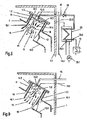
Bei der Ausführungsform der Trocknungsvorrichtung nach Fig. 6 ist der
Vakuumbehälter 1 als Gehäuse eines Transformators ausgebildet, welches das
Trocknungsgut, auch in diesem Fall das die Feststoffisolationen enthaltende Aktivteil
1.1 des Transformators aufnimmt. Das Transformatorgehäuse 1 ist in einem
Wärmeisolierhaus 1.5 angeordnet, welches vom Wärmeerzeuger 3 geheizt werden
kann. Der Wärmeerzeuger 3 ist als Lufterhitzer ausgeführt. Die Heizenergie wird
durch die Rohre 2 zugeführt. Durch die Rohre 2 erhitzte Luft wird als Wärmeträger
mit Hilfe eines Heissluftventilators 3.1 über eine Gehäusedurchführung 3.3 ins
Wärmeisolierhaus 1.5 befördert. Über eine Gehäusedurchführung 3.2 wird Luft aus
dem Wärmeisoliergehäuse 1.5 zurück zum Lufterhitzer gebracht und wieder
aufgeheizt. Auch bei dieser Ausführungsform der Trocknungsvorrichtung sind die
Heizrohre 2 mit einem Doppelmantel umgeben und werden vom Wärmeerzeuger 3
sowohl das der Transformatorgehäuse 1 als auch das Solvent aufgeheizt. Im
Unterschied zur Ausführungsform nach Fig.1 weist das Transformatorgehäuse 1
jedoch mit Abdeckflanschen 1.3 vakuumdicht verschlossene Öffnungen 1.2 auf,
durch welche Öffnungen sonst die Stromanschlüsse des Aktivteils 1.1 geführt sind. In
einer dieser Öffnungen 1.2 ist der vom Solventerhitzer 4 über die
Solventverbindungsleitung 4.1 mit heissem Solvent versorgte Strömungskanal 5.2
angeordnet. Anstelle eines Solventverteilkanals 5 mit Einspritzöffnungen 5.1 weist
bei dieser Ausführungsform der Solventdampferzeuger nun eine an der
Düsenengstelle der Venturidüse angeordnete und in Richtung der Düsenachse
ausgerichtete Einspritzdüse 5.7 auf, welche über die Leitung 4.1 mit heissem Solvent
gespeist wird. Weitere Solventdampferzeuger mit jeweils einem Strömungskanal und
mit einer oder gegebenenfalls auch mit mehreren Einspritzdüsen 5.7 können an
anderen Öffnungen 1.2 des Transformatorgehäuses 1 vorgesehen sein. Wie aus
Fig.7 entnommen werden kann, ist der Strömungskanal 5.2 im wesentlichen
axialsymmetrisch ausgebildet und ist begrenzt durch ein feststehendes und zum
grossen Teil um die Achse gebogenes Venturiblech 6.3 sowie durch das verstellbar
ausgeführte Richtblech 6. Abströmseitig ist am Richtblech 6 zusätzlich ein
Umlenkblech 6.4 angeordnet. Durch das Blech 6.4 wird aus dem Kanal 5.2
tretendes, nicht verdampftes Solvent an die Wand des Transformatorgehäuses 1
geführt und kann über eine im Boden vorgesehene Ablassöffnung 1.4 (Fig.6) rasch
wieder aus dem Gehäuse 1 entfernt und dem Solventerhitzer 4 zugeführt werden.In the embodiment of the drying apparatus of FIG. 6 is the
In einer weiteren Öffnung 1.2 Transformatorgehäuses 1 ist der Kondensationsraum
10 angeordnet. Zwei Ausführungsformen dieses Kondensationsraums sind aus den
Figuren 8 und 9 zu ersehen, wobei die Ausführungsform nach Fig.8 weitgehend der
Ausführungsform nach Fig.5 entspricht und die nach Fig.9 weitgehend derjenigen
nach Fig.4. Bei der Ausführungsform nach Fig.8 ist jedoch noch ein luftgekühlter
Kondensator 23 dargestellt, welcher mit der Austrittsöffnung 10.3 des
Kondensationsraums 10 über die Leitung 15 verbunden und dem
Mischdampfkondensator 16 unter Bildung einer zusätzlichen Kondensationsstufe für
den angereicherten Wasserdampf enthaltenden Mischdampf 14.2 vorgeschaltet ist.
Im luftgekühlten Kondensator 23 erwärmte Luft wird von einen Ventilator 23.1 über
eine Eintrittsöffnung 23.2 zu Heizzwecken ins Wärmeisoliergehäuse 1.4 befördert. Im
Kondensator 23 unter Abgabe von Kondensationswärme zum Erwärmen der Luft
abgeschiedenes Solvent wird über eine Austrittsöffnung 23.3 dem Ablaufgefäss 7
zugeführt. Verbleibender Mischdampf und Leckluft werden über eine Austrittsöffnung
23.4 dem wassergekühlten Mischdampfkondensator 16 zugeführt und entsprechend
der Trocknungsvorrichtung nach Fig.1 behandelt.In a further opening 1.2
Im Unterschied zur Ausführungsform nach Fig.1 wird bei der Trocknungsvorrichtung
nach Fig.6 der fertig montierte Transformator in das Wärmeisoliergehäuse 1
eingebracht und werden anstelle von Gehäusedurchführungen für die
Stromanschlüsse des Aktivteils 1.1 die zum Tragen der Leitung 4.1 und der
Einspritzdüse 5.7 sowie zum Abschliessen der Kondensationskammer 10 benötigten
Anschlussflansche 1.3 montiert. Mit Hilfe von flexibel ausgeführten Leitungen 4.1 und
15 sowie einer mit dem Ablauf 1.4 verbundenen Kondensatableitung wird der
Innenraum des Transformatorgehäuses 1 mit den übrigen Komponenten der
Trocknungsvorrichtung verbunden. Um diese Montagearbeit zu erleichtern, können
die Komponenten zweckmässigerweise auf verschieb- oder fahrbaren Rahmen
montiert werden. Das Trocknungsverfahren kann nun - wie bei der Ausführungsform
der Trocknungsvorrichtung nach Fig.1 beschrieben - durchgeführt werden. Im
Unterschied zum Verfahren, wie es in Zusammenhang mit der Ausführungsform nach
Fig.1 beschrieben wurde, wird nun jedoch im Kondensator 23 beim Kondensieren
von Mischdampf erwärmte Luft ins Wärmeisolierhaus 1.5 geführt. Damit wird die
Kondensationswärme des im Kondensator abgeschiedenen Solvents zur
Verbesserung des Wirkungsgrads des Trocknungsverfahrens in besonders
vorteilhafter Weise ausgenutzt. In contrast to the embodiment of Figure 1 is in the
Bei der in Fig. 10 dargestellten Ausführungsform der Trocknungsvorrichtung nach der
Erfindung ist im Vakuumbehälter 1 ein im allgemeinen als Kaskadenverdampfer
ausgebildeter Solventdampferzeuger 24 angeordnet. Diesem Dampferzeuger werden
von aussen durch die Wand des Vakuumbehälters 1 Solvent und Wärme zugeführt.
Die Menge des zugeführten Solvents wird mit Hilfe eines Solventabsperrventils 20.9
gesteuert. Die Wärme wird in einem ausserhalb des Vakuumbehälters angeordneten
Wärmeerzeuger 24.2 gebildet. Im Verdampfer 24 gebildeter Solventdampf 29 strömt
durch einen Solventdampfaustritt 24.1 in den Strömungskanal 5.2. Mit dem
Bezugszeichen 25 ist ein ausserhalb des Vakuumbehälters 1 befindlicher
Solventerhitzer bezeichnet, in dem Solvent vorgewärmt und das vorgewärmte
Solvent über ein Solventabsperrventil 20.8 dosiert in den im Strömungskanal 5.2
befindlichen Solventverteilkanal 5 geführt wird. Die Einspritzdüsen 5.7 des
Solventverteilkanals 5 sind im Bereich der Engstelle der Venturidüse angeordnet.In the embodiment of the drying device according to FIG
Invention is in the vacuum tank 1 a generally as a cascade evaporator
trained
Das in Richtung des Solventdampfstroms 29 eingespritzte vorgewärmte Solvent 5.3
saugt infolge Jetwirkung den Solventdampf aus dem Verdampfer 24 und erhöht so
dessen Strömungsgeschwindigkeit. Zugleich wird auch die Geschwindigkeit des im
Strömungskanal 5.2 bereits geführten Mischdampfstroms 30 erhöht. Der aus dem
Strömungskanal 5.2 tretende Dampfstrom 5.4 weist daher eine hohe
Strömungsgeschwindigkeit und eine gute Turbulenz auf. Hieraus resultieren eine
höhere Strömungsgeschwindigkeit und eine bessere Turbulenz des im
Vakuumbehälter zirkulierenden Solventdampfstroms als bei herkömmlichen
Verfahren. Dadurch werden die Trockenzeiten bei gleichzeitig geringem
Energiebedarf reduziert. Infolge der Jetwirkung bleibt bleibt die erwünscht hohe
Solventdampfgeschwindigkeit im Autoklaven auch gegen Ende der Aufheizphase
erhalten. Dies führt zu einer kürzeren Aufheizzeit im oberen Temperaturbereich und
stellt dementsprechend auch eine kleine Temperaturdifferenz über dem
Trocknungsgut 1.1 und damit auch eine verbesserte Trocknungsqualität sicher.The preheated solvent 5.3 injected in the direction of the
Bei der Ausführungsform der erfindungsgemässen Trocknungsvorrichtung nach
Fig.11 wird im Unterschied zur Ausführungsform nach Fig.10 der Solventdampfstrom
29 in einem ausserhalb des Vakuumgefässes 1 angeordneten externen
Solventverdampfer 26, beispielsweise einem Grossverdampfer oder einem
Fallrohrverdampfer, erzeugt und über eine einen Zutrittsstutzen 27 und ein
Umlenkblech 28 enthaltende Dampfleitung an den Strömungskanal 5.2 geführt.
Durch die Jetwirkung des in Richtung des Dampfstroms 29 eingespritzten erwärmten
Solvents werden analog der Ausführungsform gemäss Fig.10 der Solventdampf aus
der Dampfleitung und der Mischdampf aus dem Autoklaven 1 abgesaugt und werden
so die Strömungsgeschwindigkeit und die Turbulenz des Dampfstroms 5.4 in
vorteilhafter Weise erhöht.In the embodiment of the inventive drying device according to
11, in contrast to the embodiment according to FIG. 10, the
- 11
- Vakuumbehälter, TransformatorgehäuseVacuum container, transformer housing
- 1.11.1
- Trocknungsgut (elektrisches Gerät, Aktivteil des Geräts)Drying material (electrical device, active part of the device)
- 1.21.2
- Gehäuseöffnungenhousing openings
- 1.31.3
- Abdeckflanschecovering flange
- 1.41.4
- Kondensatablaufcondensate drain
- 1.51.5
- WärmeisolierhausWärmeisolierhaus
- 22
- Heizrohreheating pipes
- 33
- Wärmeerzeuger, LufterhitzerHeat generator, air heater
- 3.13.1
- HeissluftventilatorHot air fan
- 3.2, 3.33.2, 3.3
- GehäusedurchführungenEnclosure openings
- 44
- SolventerhitzerSolventerhitzer
- 4.14.1
- SolventverbindungsleitungSolvent connecting line
- 4.24.2
- SolventzuführleitungSolventzuführleitung
- 55
- SolventverteilkanalSolventverteilkanal
- 5.15.1
- EinspritzöffnungInjection port
- 5.25.2
- Strömungskanalflow channel
- 5.35.3
- erwärmtes Solventheated solvent
- 5.45.4
- Solventdampfsolvent vapor
- 5.55.5
-
Lage eines Richtblechs 6 für maximale Eintrittsfläche von 5.2Location of a straightening
plate 6 for maximum entry area of 5.2 - 5.65.6
-
Lage eines Richtblechs 6 für minimale Eintrittsfläche von 5.2Location of a straightening
plate 6 for minimum entry area of 5.2 - 5.75.7
- Einspritzdüseinjection
- 66
- Richtblechdirectional sheet
- 6.16.1
- Drehpunkt des RichtblechsFulcrum of the straightening plate
- 6.26.2
- Einstellvorrichtung für das RichtblechAdjustment device for the straightening plate
- 6.36.3
- Venturiblechventuri sheet
- 6.46.4
- Umlenkblechbaffle
- 77
- Ablaufbehälterdrain tank
- 7.17.1
- Füllstandsindikatorlevel indicator
- 8, 8.18, 8.1
- Förderpumpenfeed pumps
- 99
- SolventvorratstankSolvent supply tank
- 1010
- Kondensationsraum der WärmerekuperationCondensation room of heat recuperation
- 10.110.1
- Leitblechbaffle
- 10.210.2
- Umlenkblechbaffle
- 10.310.3
- Austrittsöffnungoutlet opening
- 10.410.4
- Abflussblechdrain sheet
- 1111
- Einspritzdüsen injectors
- 1212
- Richtblechdirectional sheet
- 1313
- MischdampfstromMixed vapor stream
- 1414
- kaltes Solventcold solvent
- 14.114.1
- Kondensiertes SolventCondensed solvent
- 14.214.2
- Solventdampf mit angereichertem WasserdampfSolvent vapor with enriched water vapor
- 14.314.3
- SolventleitungSolvent line
- 1515
- MischdampfleitungMixing steam line
- 1616
- MischdampfkondensatorMixing steam condenser
- 1717
- Trennbehälterseparation vessel
- 1818
- Vakuumanlagevacuum system
- 1919
- Öltankoil tank
- 2020
- Dampfabsperrventilsteam regulator
- 20.1-20.720.1-20.7
- Solvent-ÖlabsperrventileSolvent-Ölabsperrventile
- 20.8, 20,920.8, 20.9
- SolventabsperrventileSolventabsperrventile
- 2121
- Solvent-VakuumabsperrventilSolvent-vacuum shut
- 2222
- WasserablassventilWater drain valve
- 2323
- luftgekühlter Kondensatorair-cooled condenser
- 23.123.1
- Ventilatorfan
- 23.223.2
- Eintrittsöffnunginlet opening
- 23.323.3
- Austrittsöffnung (Solventkondensat)Outlet opening (solvent condensate)
- 23.423.4
- Austrittsöffnung (Mischdampf)Outlet opening (mixed steam)
- 2424
- (intemer) Solventverdampfer(internal) solvent evaporator
- 24.124.1
- SolventdampfaustrittSolvent steam outlet
- 24.224.2
- Wärmeerzeugerheat generator
- 2525
- SolventerhitzerSolventerhitzer
- 2626
- (externer) Solventverdampfer(external) solvent evaporator
- 2727
- Zutrittsstutzenaccess nozzle
- 2828
- Umlenkblechbaffle
- 2929
- SolventdampfstromSolvent vapor stream
- 3030
- MischdampfstromMixed vapor stream
Claims (17)
Priority Applications (1)
| Application Number | Priority Date | Filing Date | Title |
|---|---|---|---|
| EP04405298A EP1528342B1 (en) | 2003-10-31 | 2004-05-10 | Process for drying material and apparatus for carrying out the process |
Applications Claiming Priority (3)
| Application Number | Priority Date | Filing Date | Title |
|---|---|---|---|
| EP03405783 | 2003-10-31 | ||
| EP03405783 | 2003-10-31 | ||
| EP04405298A EP1528342B1 (en) | 2003-10-31 | 2004-05-10 | Process for drying material and apparatus for carrying out the process |
Publications (3)
| Publication Number | Publication Date |
|---|---|
| EP1528342A2 true EP1528342A2 (en) | 2005-05-04 |
| EP1528342A3 EP1528342A3 (en) | 2005-07-20 |
| EP1528342B1 EP1528342B1 (en) | 2006-08-30 |
Family
ID=34424789
Family Applications (1)
| Application Number | Title | Priority Date | Filing Date |
|---|---|---|---|
| EP04405298A Expired - Lifetime EP1528342B1 (en) | 2003-10-31 | 2004-05-10 | Process for drying material and apparatus for carrying out the process |
Country Status (1)
| Country | Link |
|---|---|
| EP (1) | EP1528342B1 (en) |
Cited By (3)
| Publication number | Priority date | Publication date | Assignee | Title |
|---|---|---|---|---|
| EP2525178A1 (en) * | 2011-05-18 | 2012-11-21 | Micavac AG | Method for drying a solid isolation containing active section of an electric device which can be filled with impregnating oil and device for performing this method |
| DE102014101298A1 (en) * | 2014-02-03 | 2015-08-06 | Inter-Consult Gmbh | Method and device for heating, cleaning and drying of drying goods |
| WO2019102399A3 (en) * | 2017-11-22 | 2019-10-17 | Sociedad De Ingeniería Ambiental Ltda | Solvent extraction equipment, allowing efficient energy usage through the reuse of the solvent(s) |
Families Citing this family (2)
| Publication number | Priority date | Publication date | Assignee | Title |
|---|---|---|---|---|
| EP2148157B1 (en) | 2008-07-25 | 2013-02-27 | Paul Gmeiner | Device for heating and drying a good according to the vapour-phase method |
| EP3029403B1 (en) | 2014-12-03 | 2017-12-20 | Paul Gmeiner | Method and device for drying the solid insulation of the active section of an electrical device using the vapour-phase method |
Citations (2)
| Publication number | Priority date | Publication date | Assignee | Title |
|---|---|---|---|---|
| DE3014831A1 (en) | 1980-02-29 | 1981-09-17 | Micafil AG, 8048 Zürich | CASCADES EVAPORATOR FOR CONDENSATION DRYING DEVICES |
| US20020184784A1 (en) | 2000-09-05 | 2002-12-12 | Helmut Strzala | Device for preparing transformers |
Family Cites Families (5)
| Publication number | Priority date | Publication date | Assignee | Title |
|---|---|---|---|---|
| DE1211553B (en) * | 1958-03-18 | 1966-02-24 | Konrad Kieferle | Dryer, e.g. B. drying cabinet |
| FR1398812A (en) * | 1964-03-24 | 1965-05-14 | Vide Soc Gen Du | Improvements to the drying of insulating materials |
| DE19608974C1 (en) * | 1996-03-08 | 1997-03-06 | Sicowa Verfahrenstech | Drying charge in high pressure steam autoclave |
| EP1253389B1 (en) * | 2001-04-24 | 2005-11-16 | ABB Schweiz AG | Process for drying an active part, and apparatus for carrying out this process |
| US6702101B2 (en) * | 2001-12-21 | 2004-03-09 | Spraying Systems Co. | Blower operated airknife with air augmenting shroud |
-
2004
- 2004-05-10 EP EP04405298A patent/EP1528342B1/en not_active Expired - Lifetime
Patent Citations (2)
| Publication number | Priority date | Publication date | Assignee | Title |
|---|---|---|---|---|
| DE3014831A1 (en) | 1980-02-29 | 1981-09-17 | Micafil AG, 8048 Zürich | CASCADES EVAPORATOR FOR CONDENSATION DRYING DEVICES |
| US20020184784A1 (en) | 2000-09-05 | 2002-12-12 | Helmut Strzala | Device for preparing transformers |
Non-Patent Citations (3)
| Title |
|---|
| GMEINER P.K.: "Modern vapour drying processes and plants", MICAFIL VAKUUMTECHNIK AG, February 1992 (1992-02-01), ZÜRICH |
| MEYERS S.D.; KELLY J.J.; PARISH P.H.: "Guide to Transformer Maintenance", 1981, TRANSFORMER MAINTENANE INSTITUTE,DIVISION,S.D.MEYERS,INC.AKRON, OHIO, pages: 496 |
| OESCH G.; SCHATZL H.: "Die Solventdampftrocknung und Leistungstransformatoren", MICAFIL AG, August 1976 (1976-08-01), ZÜRICH |
Cited By (4)
| Publication number | Priority date | Publication date | Assignee | Title |
|---|---|---|---|---|
| EP2525178A1 (en) * | 2011-05-18 | 2012-11-21 | Micavac AG | Method for drying a solid isolation containing active section of an electric device which can be filled with impregnating oil and device for performing this method |
| DE102014101298A1 (en) * | 2014-02-03 | 2015-08-06 | Inter-Consult Gmbh | Method and device for heating, cleaning and drying of drying goods |
| DE102014101298B4 (en) | 2014-02-03 | 2019-03-14 | Inter-Consult Gmbh | Method and device for heating, cleaning and drying of drying goods |
| WO2019102399A3 (en) * | 2017-11-22 | 2019-10-17 | Sociedad De Ingeniería Ambiental Ltda | Solvent extraction equipment, allowing efficient energy usage through the reuse of the solvent(s) |
Also Published As
| Publication number | Publication date |
|---|---|
| EP1528342A3 (en) | 2005-07-20 |
| EP1528342B1 (en) | 2006-08-30 |
Similar Documents
| Publication | Publication Date | Title |
|---|---|---|
| DE19754897A1 (en) | Dryer employing water-soluble solvent vapour | |
| DE19503591A1 (en) | Method and device for extracting a sample | |
| DE2544343B2 (en) | Process for the production of white cement and plant for carrying out the process | |
| DE10234710B4 (en) | System for drying semiconductor substrates | |
| EP1528342B1 (en) | Process for drying material and apparatus for carrying out the process | |
| DE2366052A1 (en) | TOBACCO DRYERS | |
| EP2148157B1 (en) | Device for heating and drying a good according to the vapour-phase method | |
| EP0752567B1 (en) | Process for drying the solid insulation of an electrical device, and apparatus for carrying out this process | |
| EP2525178B1 (en) | Method for drying a solid isolation containing active section of an electric device which can be filled with impregnating oil and device for performing this method | |
| EP3165859A1 (en) | Vacuum cooling device and method for the vacuum cooling of foodstuff | |
| EP2308576B1 (en) | Vaporiser | |
| DE2850019A1 (en) | Condensable components separation from gas - using vortex chamber keeping raw and hot gas pressure to specimen ratio | |
| DE19712993A1 (en) | Apparatus for heating and degassing water | |
| DE3001995C2 (en) | ||
| DE19502489C2 (en) | Heat consumer Station | |
| EP0463448A1 (en) | Method and apparatus for heating and multiple effect degasification of water | |
| EP3029403B1 (en) | Method and device for drying the solid insulation of the active section of an electrical device using the vapour-phase method | |
| DE649672C (en) | Process and plant for the evaporation of liquid | |
| DE2724268C3 (en) | Method and device for regulating the drying of goods | |
| DE10245935A1 (en) | Venting / degassing system for power plant condensers | |
| EP0214934B1 (en) | Evaporation apparatus and installation with such an apparatus for the desalination of sea water | |
| EP1225991A1 (en) | Method for conditioning foundry moulding sand and a device therefor | |
| DE837911C (en) | Process for the treatment, in particular for the odor-freeing of fatty oils and fats and device for carrying out the process | |
| DE102004029814B3 (en) | Process to condition molten sugar mass in a steam out chamber in which the mass molten forms part of the gaseous phase | |
| DE2718751A1 (en) | METHOD AND DEVICE FOR DISPOSING OF USED WORKING FLUIDS |
Legal Events
| Date | Code | Title | Description |
|---|---|---|---|
| PUAI | Public reference made under article 153(3) epc to a published international application that has entered the european phase |
Free format text: ORIGINAL CODE: 0009012 |
|
| AK | Designated contracting states |
Kind code of ref document: A2 Designated state(s): AT BE BG CH CY CZ DE DK EE ES FI FR GB GR HU IE IT LI LU MC NL PL PT RO SE SI SK TR |
|
| AX | Request for extension of the european patent |
Extension state: AL HR LT LV MK |
|
| PUAL | Search report despatched |
Free format text: ORIGINAL CODE: 0009013 |
|
| AK | Designated contracting states |
Kind code of ref document: A3 Designated state(s): AT BE BG CH CY CZ DE DK EE ES FI FR GB GR HU IE IT LI LU MC NL PL PT RO SE SI SK TR |
|
| AX | Request for extension of the european patent |
Extension state: AL HR LT LV MK |
|
| 17P | Request for examination filed |
Effective date: 20051021 |
|
| GRAP | Despatch of communication of intention to grant a patent |
Free format text: ORIGINAL CODE: EPIDOSNIGR1 |
|
| AKX | Designation fees paid |
Designated state(s): CH DE FR GB LI SE |
|
| GRAS | Grant fee paid |
Free format text: ORIGINAL CODE: EPIDOSNIGR3 |
|
| GRAA | (expected) grant |
Free format text: ORIGINAL CODE: 0009210 |
|
| AK | Designated contracting states |
Kind code of ref document: B1 Designated state(s): CH DE FR GB LI SE |
|
| PG25 | Lapsed in a contracting state [announced via postgrant information from national office to epo] |
Ref country code: GB Free format text: LAPSE BECAUSE OF FAILURE TO SUBMIT A TRANSLATION OF THE DESCRIPTION OR TO PAY THE FEE WITHIN THE PRESCRIBED TIME-LIMIT Effective date: 20060830 |
|
| REG | Reference to a national code |
Ref country code: GB Ref legal event code: FG4D Free format text: NOT ENGLISH |
|
| REG | Reference to a national code |
Ref country code: CH Ref legal event code: EP |
|
| REF | Corresponds to: |
Ref document number: 502004001330 Country of ref document: DE Date of ref document: 20061012 Kind code of ref document: P |
|
| REG | Reference to a national code |
Ref country code: SE Ref legal event code: TRGR |
|
| GBV | Gb: ep patent (uk) treated as always having been void in accordance with gb section 77(7)/1977 [no translation filed] |
Effective date: 20060830 |
|
| EN | Fr: translation not filed | ||
| PLBI | Opposition filed |
Free format text: ORIGINAL CODE: 0009260 |
|
| PLAX | Notice of opposition and request to file observation + time limit sent |
Free format text: ORIGINAL CODE: EPIDOSNOBS2 |
|
| 26 | Opposition filed |
Opponent name: WILHELM HEDRICH VAKUUMANLAGEN GMBH & CO. KG Effective date: 20070526 |
|
| PLBB | Reply of patent proprietor to notice(s) of opposition received |
Free format text: ORIGINAL CODE: EPIDOSNOBS3 |
|
| PG25 | Lapsed in a contracting state [announced via postgrant information from national office to epo] |
Ref country code: FR Free format text: LAPSE BECAUSE OF FAILURE TO SUBMIT A TRANSLATION OF THE DESCRIPTION OR TO PAY THE FEE WITHIN THE PRESCRIBED TIME-LIMIT Effective date: 20070511 |
|
| PG25 | Lapsed in a contracting state [announced via postgrant information from national office to epo] |
Ref country code: FR Free format text: LAPSE BECAUSE OF FAILURE TO SUBMIT A TRANSLATION OF THE DESCRIPTION OR TO PAY THE FEE WITHIN THE PRESCRIBED TIME-LIMIT Effective date: 20060830 |
|
| PLCK | Communication despatched that opposition was rejected |
Free format text: ORIGINAL CODE: EPIDOSNREJ1 |
|
| APBM | Appeal reference recorded |
Free format text: ORIGINAL CODE: EPIDOSNREFNO |
|
| APBP | Date of receipt of notice of appeal recorded |
Free format text: ORIGINAL CODE: EPIDOSNNOA2O |
|
| APAH | Appeal reference modified |
Free format text: ORIGINAL CODE: EPIDOSCREFNO |
|
| APAH | Appeal reference modified |
Free format text: ORIGINAL CODE: EPIDOSCREFNO |
|
| APBQ | Date of receipt of statement of grounds of appeal recorded |
Free format text: ORIGINAL CODE: EPIDOSNNOA3O |
|
| APBU | Appeal procedure closed |
Free format text: ORIGINAL CODE: EPIDOSNNOA9O |
|
| PLBN | Opposition rejected |
Free format text: ORIGINAL CODE: 0009273 |
|
| STAA | Information on the status of an ep patent application or granted ep patent |
Free format text: STATUS: OPPOSITION REJECTED |
|
| 27O | Opposition rejected |
Effective date: 20110519 |
|
| REG | Reference to a national code |
Ref country code: DE Ref legal event code: R100 Ref document number: 502004001330 Country of ref document: DE Effective date: 20110519 |
|
| PGFP | Annual fee paid to national office [announced via postgrant information from national office to epo] |
Ref country code: CH Payment date: 20220815 Year of fee payment: 19 |
|
| PGFP | Annual fee paid to national office [announced via postgrant information from national office to epo] |
Ref country code: DE Payment date: 20230606 Year of fee payment: 20 |
|
| PGFP | Annual fee paid to national office [announced via postgrant information from national office to epo] |
Ref country code: SE Payment date: 20230710 Year of fee payment: 20 |
|
| REG | Reference to a national code |
Ref country code: CH Ref legal event code: PL |
|
| PG25 | Lapsed in a contracting state [announced via postgrant information from national office to epo] |
Ref country code: LI Free format text: LAPSE BECAUSE OF NON-PAYMENT OF DUE FEES Effective date: 20230531 Ref country code: CH Free format text: LAPSE BECAUSE OF NON-PAYMENT OF DUE FEES Effective date: 20230531 |
|
| REG | Reference to a national code |
Ref country code: DE Ref legal event code: R071 Ref document number: 502004001330 Country of ref document: DE |
|
| REG | Reference to a national code |
Ref country code: SE Ref legal event code: EUG |