EP1528227A1 - Means to counterbalance torque fluctuations in a camshaft - Google Patents
Means to counterbalance torque fluctuations in a camshaft Download PDFInfo
- Publication number
- EP1528227A1 EP1528227A1 EP04255991A EP04255991A EP1528227A1 EP 1528227 A1 EP1528227 A1 EP 1528227A1 EP 04255991 A EP04255991 A EP 04255991A EP 04255991 A EP04255991 A EP 04255991A EP 1528227 A1 EP1528227 A1 EP 1528227A1
- Authority
- EP
- European Patent Office
- Prior art keywords
- cam
- cam lobe
- outer cylinder
- rotating shaft
- disposed
- Prior art date
- Legal status (The legal status is an assumption and is not a legal conclusion. Google has not performed a legal analysis and makes no representation as to the accuracy of the status listed.)
- Withdrawn
Links
- 230000005540 biological transmission Effects 0.000 claims 1
- 239000011796 hollow space material Substances 0.000 claims 1
- RDYMFSUJUZBWLH-UHFFFAOYSA-N endosulfan Chemical compound C12COS(=O)OCC2C2(Cl)C(Cl)=C(Cl)C1(Cl)C2(Cl)Cl RDYMFSUJUZBWLH-UHFFFAOYSA-N 0.000 description 5
- 238000002485 combustion reaction Methods 0.000 description 3
- 230000001360 synchronised effect Effects 0.000 description 2
- 230000008878 coupling Effects 0.000 description 1
- 238000010168 coupling process Methods 0.000 description 1
- 238000005859 coupling reaction Methods 0.000 description 1
- 230000003247 decreasing effect Effects 0.000 description 1
Images


Classifications
-
- F—MECHANICAL ENGINEERING; LIGHTING; HEATING; WEAPONS; BLASTING
- F01—MACHINES OR ENGINES IN GENERAL; ENGINE PLANTS IN GENERAL; STEAM ENGINES
- F01L—CYCLICALLY OPERATING VALVES FOR MACHINES OR ENGINES
- F01L1/00—Valve-gear or valve arrangements, e.g. lift-valve gear
- F01L1/12—Transmitting gear between valve drive and valve
- F01L1/14—Tappets; Push rods
- F01L1/143—Tappets; Push rods for use with overhead camshafts
-
- F—MECHANICAL ENGINEERING; LIGHTING; HEATING; WEAPONS; BLASTING
- F01—MACHINES OR ENGINES IN GENERAL; ENGINE PLANTS IN GENERAL; STEAM ENGINES
- F01L—CYCLICALLY OPERATING VALVES FOR MACHINES OR ENGINES
- F01L1/00—Valve-gear or valve arrangements, e.g. lift-valve gear
- F01L1/02—Valve drive
- F01L1/04—Valve drive by means of cams, camshafts, cam discs, eccentrics or the like
- F01L1/047—Camshafts
- F01L1/053—Camshafts overhead type
- F01L1/0532—Camshafts overhead type the cams being directly in contact with the driven valve
-
- F—MECHANICAL ENGINEERING; LIGHTING; HEATING; WEAPONS; BLASTING
- F01—MACHINES OR ENGINES IN GENERAL; ENGINE PLANTS IN GENERAL; STEAM ENGINES
- F01L—CYCLICALLY OPERATING VALVES FOR MACHINES OR ENGINES
- F01L1/00—Valve-gear or valve arrangements, e.g. lift-valve gear
- F01L1/02—Valve drive
- F01L1/04—Valve drive by means of cams, camshafts, cam discs, eccentrics or the like
- F01L1/08—Shape of cams
-
- F—MECHANICAL ENGINEERING; LIGHTING; HEATING; WEAPONS; BLASTING
- F01—MACHINES OR ENGINES IN GENERAL; ENGINE PLANTS IN GENERAL; STEAM ENGINES
- F01L—CYCLICALLY OPERATING VALVES FOR MACHINES OR ENGINES
- F01L1/00—Valve-gear or valve arrangements, e.g. lift-valve gear
- F01L1/34—Valve-gear or valve arrangements, e.g. lift-valve gear characterised by the provision of means for changing the timing of the valves without changing the duration of opening and without affecting the magnitude of the valve lift
- F01L1/344—Valve-gear or valve arrangements, e.g. lift-valve gear characterised by the provision of means for changing the timing of the valves without changing the duration of opening and without affecting the magnitude of the valve lift changing the angular relationship between crankshaft and camshaft, e.g. using helicoidal gear
- F01L1/34409—Valve-gear or valve arrangements, e.g. lift-valve gear characterised by the provision of means for changing the timing of the valves without changing the duration of opening and without affecting the magnitude of the valve lift changing the angular relationship between crankshaft and camshaft, e.g. using helicoidal gear by torque-responsive means
-
- F—MECHANICAL ENGINEERING; LIGHTING; HEATING; WEAPONS; BLASTING
- F01—MACHINES OR ENGINES IN GENERAL; ENGINE PLANTS IN GENERAL; STEAM ENGINES
- F01L—CYCLICALLY OPERATING VALVES FOR MACHINES OR ENGINES
- F01L1/00—Valve-gear or valve arrangements, e.g. lift-valve gear
- F01L1/46—Component parts, details, or accessories, not provided for in preceding subgroups
- F01L1/462—Valve return spring arrangements
-
- F—MECHANICAL ENGINEERING; LIGHTING; HEATING; WEAPONS; BLASTING
- F01—MACHINES OR ENGINES IN GENERAL; ENGINE PLANTS IN GENERAL; STEAM ENGINES
- F01L—CYCLICALLY OPERATING VALVES FOR MACHINES OR ENGINES
- F01L13/00—Modifications of valve-gear to facilitate reversing, braking, starting, changing compression ratio, or other specific operations
- F01L13/0015—Modifications of valve-gear to facilitate reversing, braking, starting, changing compression ratio, or other specific operations for optimising engine performances by modifying valve lift according to various working parameters, e.g. rotational speed, load, torque
- F01L13/0036—Modifications of valve-gear to facilitate reversing, braking, starting, changing compression ratio, or other specific operations for optimising engine performances by modifying valve lift according to various working parameters, e.g. rotational speed, load, torque the valves being driven by two or more cams with different shape, size or timing or a single cam profiled in axial and radial direction
-
- F—MECHANICAL ENGINEERING; LIGHTING; HEATING; WEAPONS; BLASTING
- F01—MACHINES OR ENGINES IN GENERAL; ENGINE PLANTS IN GENERAL; STEAM ENGINES
- F01L—CYCLICALLY OPERATING VALVES FOR MACHINES OR ENGINES
- F01L1/00—Valve-gear or valve arrangements, e.g. lift-valve gear
- F01L1/02—Valve drive
- F01L1/04—Valve drive by means of cams, camshafts, cam discs, eccentrics or the like
- F01L1/047—Camshafts
- F01L2001/0478—Torque pulse compensated camshafts
Definitions
- This invention relates to the use of cams in mechanical systems. More particularly, the invention pertains to means to add torsional energy to a camshaft to extend the range of a cam torque actuated cam phaser.
- a camshaft for use in an internal combustion engine of a type having spring loaded cam followers experiences a series of oppositely directed torque pulses during each revolution of the camshaft.
- the positive-going portion of each pulse occurs as a result of the need to apply torque to the camshaft to cause each of its operating cams to rotate against the force of the cam follower during the opening of the valve which is operated by such cam follower, and the negative-going portion occurs as the result of the application of an oppositely directed torque to the camshaft as the operating cam resists the force of the cam follower during the closing of the valve.
- the resulting torque pulses can be used for actuation purposes, e.g., as a means for providing a control signal to a variable cam timing system (VCT) as disclosed in U.S. Pat. No. 5,002,023.
- VCT variable cam timing system
- the present invention incorporates by reference the disclosure of said U.S. patent.
- the torque pulses may not be of sufficient magnitude for actuation of a VCT system according to U.S. Pat. No. 5,002,023. In these cases the torque pulses must be amplified to be utilized effectively.
- U.S. Pat. No. 5 , 107 , 805 discloses a torque amplifying camshaft for operating a valve of each of a plurality valves of an internal combustion engine, the camshaft having an elongagted, shaftlike portion and an engine valve operating cam for each of the valves, the valve operating cams being spaced apart from one another along the shaftlike portion.
- Each of the engine valve operating cams has an outwardly projecting portion, and the outwardly projecting portions are circumferentially offset from one another about the longitudinal central axis of the camshaft.
- the camshaft also carries a supplementary cam surface, either in the form of an outwardly facing surface of a separate supplementary cam or an inwardly facing surface of a portion of a drive sprocket which is keyed to the shaftlike portion.
- the supplementary cam surface is adapted to be followed by a spring biased supplementary cam follower and has portions which introduce torque pulses into the camshaft which are synchronous with and consistently directed with respect to the torque pulses that are introduced into the camshaft by the engagement between the valve operating cams and spring biased followers which engage such valve operating cams.
- U.S. Pat. No. 5,040,500 discloses a torque compensated camshaft for operating a valve of each of a plurality of valves of an internal combustion engine, the camshaft having an elongate shaftlike portion and an engine valve operating cam for each of the valves, the valve operating cams being spaced apart from one another along the shaftlike portion.
- Each of the engine valve operating cams has an outwardly projecting portion, and the outwardly projecting portions are circumferentially offset from one another about the longitudinal central axis of the camshaft.
- the camshaft also carries a compensating cam surface, either in the form of an outwardly facing surface of a separate compensating cam or an inwardly facing surface of a portion of a drive sprocket which is keyed to the shaftlike portion.
- the compensating cam surface is adapted to be followed by a spring biased compensating cam follower and has portions which introduce torque pulses into the camshaft which are synchronous with and oppositely directed with respect to the torque pulses that are introduced into the camshaft by the engagement between the valve operating cams and spring biased followers which engage such valve operating cams.
- cam lobe takes significant space such as extra length of a cam shaft.
- Many engines do not have the space for accommodating this type extra lobe in the engine compartment. Therefore, it is desirable to provide extra lobes that do not occupy excessive space in which the accommodating extra lobes are located.
- a device that adds torsional energy to a camshaft is provided.
- the added torsional energy of the camshaft is used to extend the range a cam torque actuated (CTA) cam phaser.
- CTA cam torque actuated
- the added torsional energy of the camshaft may also be used to extend the range other types of phasers such as torque actuated (TA) as well.
- a device that adds torsional energy to a camshaft without an additional cam lobe added to the length of the cam shaft is provided.
- a device for providing additional torsional energy for a cam shaft includes at least one main cam lobe formed on a rotating shaft; a valve operating mechanism disposed to be engaged by the main cam lobe; and an outer cylinder encompassing the valve operating mechanism, and capable of movement that is independent of the valve operating mechanism, the outer cylinder being disposed to provide torsional energy to the rotating shaft.
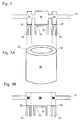
- a cam shaft (10) having a plurality of cam lobs (only one shown) formed thereon for controlling valves such as valve (12) is provided.
- Cam shaft (10) may control valve (12) in any known manner.
- main cam lobe (14) may rotably engage a top surface (16) of an inverted bucket mechanical lifter (18).
- valve (12) opens or closes as desired.
- Valve (12) includes a valve stem (22) having an elongated shape with one end coupled to a valve spring (24). The coupling is achieved via a lock groove (26) on the one end of valve stem (22), in which the lock groove (26) facilitates the positioning of a valve guide or keeper (28).
- An outer cylinder (30) encompasses or holds the above described elements within itself, i.e. within outer cylinder (30).
- Outer cylinder (30) has a top engaging surface (32) that suitably engages a pair of accompanying cam lobes (34) formed on cam shaft (10) at each side of main cam lobe (14).
- Outer cylinder (30) may be a hollow member having a cylinder spring (36) positioned within the hollow. Alternatively, cylinder spring (36) may be at other suitable locations such as on top or below outer cylinder (30). Cylinder spring (36) is independent of valve spring (24).
- mechanical lifter (18) is not rigidly connected to outer cylinder (30). Mechanical lifter (18) can move or slide relative to outer cylinder (30).
- FIG. 1 the first perspective view of the present invention wherein cam nose (20) is not engaging top surface (16) of mechanical lifter (18) is depicted.
- cam nose (20) is not pressing valve (12) downward.
- FIG. 1A the second perspective view of the present invention wherein cam nose (20) is engaging top surface (16) of mechanical lifter (18) is depicted.
- cam nose (20) is pressing valve (12) downward.
- Main cam lobe (14) is formed on cam shaft (10) as a single member or block.
- the pair of accompanying cam lobes (34) is formed on cam shaft (10) as a single block as well.
- Accompanying cam lobes (34) rotably engages top engaging surface (32) of outer cylinder (30).
- Accompanying cam lobes (34) possess a cam shape wherein under most circumstances the engagement of accompanying cam lobes (34) with outer cylinder (30) at different positions (e.g. 2 positions) of rotation of cam shaft (10) corresponds to a pair of different relative distances between a center of cam shaft (10) and top engaging surface (32). This may be shown by the difference in length of an upper gap (400) and a lower gap (420).
- valve (12) has valve stem (22). On valve stem (22) lock groove (26) is formed thereon for keeper (28) to secure valve spring (24).
- Mechanical lifter (18) has top surface (16) for receiving action from main cam lobe (14).
- Outer cylinder (30) has cylinder spring (36) for aiding the generation of torsional energy. Cylinder spring (36) is independent of valve spring (24). Further, outer cylinder (30) can move freely relative to mechanical lifter (18). In other words, outer cylinder (30) can move freely relative to mechanical lifter (18). As can be seen, this free movement is a key feature needed for the generation of torsional energy of the present invention.
- Outer cylinder (30) may be rested on the engine block (43), or some other member (not shown) interposed between engine block (43) and outer cylinder (30).
- a line of force (not shown) can be achieved wherein the force conjoins or is being exerted upon each of the members including (34), additional cylinder (30) via engaging surface (32), cylinder spring (36), and engine block (43).
- additional torsional energy are provided for the cam shaft (10).
- FIG. 2 the first perspective view of the present invention wherein cam nose (20) is not engaging top surface (16) of mechanical lifter (18) is depicted.
- cam nose (20) is not pressing valve (12) downward.
- FIG. 2A the second perspective view of the present invention wherein cam nose (20) is engaging top surface (16) of mechanical lifter (18) is depicted.
- cam nose (20) is pressing valve (12) downward.
- Cam shaft (10) has main cam lobe (14) and a pair of accompanying cam lobes (34) formed thereon.
- Main cam lobe (14) is engaging mechanical lifter (18) and the pair of accompanying cam lobes (34) is respectively engaging top engaging surface (32).
- outer cylinder (30) that encompasses mechanical lifter (18) is shown.
- Mechanical lifter (18) may include therein any suitable known valve operating mechanism.
- outer cylinder (30) that encompasses mechanical lifter (18) is shown.
- Mechanical lifter (18) may include therein any suitable known valve operating mechanism.
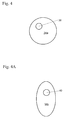
- First embodiment (34a) is a circle or round disk that is non concentric having a first center region (38).
- Center (38) is aligned with a center line (not shown) of cam shaft (10).
- center (38) rotates in line with the centerline of cam shaft (10)
- any two points on the circumference of the non concentric disk, or first embodiment (34a) apparently each has an unequal distance to a center point of center (38). Therefore, the cam shape of first embodiment (34a) with its concomitant characteristics forms the necessary basis for the generation of torsional energy of the cam shaft (10).
- a second embodiment (34b) of accompany cam lobe is shown.
- the second embodiment (34b) is an oval shaped disk having a center region (40) which may or may not the physical center of the disk.
- Second center (40) is aligned with a center line (not shown) of cam shaft (10).
- any two adjacent points on the circumference of the oval disk, or second embodiment (34b) apparently each has an unequal distance to a center point of second center (40). Therefore, the cam shape of second embodiment (34b) with its concomitant characteristics forms the necessary basis for the generation of torsional energy of the cam shaft (10).
- a means may be provided for adding torsional energy to a camshaft to extend the range of a cam torque actuated Cam Phaser.
- an extra cam lobe which may significantly extend the length of the cam shaft
- an extra lobe that requires very little extra room is provided in the immediate neighborhood of at least on existing cam lobe.
- an additional full fledged cam lobe may significantly add to the length of the cam shaft.
- Many engines do not have the space within the engine compartment to accommodate this additional full fledged lobe.
- the present invention provides one or more extra lobes that requires very little extra room.
- the present invention further includes a cylinder such as outer cylinder (30) being added around an inverted bucket mechanical lifter (e.g. mechanical lifter (18)) with a spring (e.g. 36) encased inside outer cylinder (30).
- a cylinder such as outer cylinder (30) being added around an inverted bucket mechanical lifter (e.g. mechanical lifter (18)) with a spring (e.g. 36) encased inside outer cylinder (30).
- Two extra lobes such as accompanying cam lobes (34) are added on either side of the main valve lobe such as main cam lobe (14).
- These accompanying cam lobes (34) may be as simple as circle that is non concentric (see Fig. 4).
- accompanying cam lobes (34) may be of the same shape as the main cam lobe (14) that opens and closes the valve (12).
- Fig. 5 is a set of graphs depicting a comparison of systems with and without the present invention.
- Graph (44) shows torques of about the same intensity.
- torque T possesses about the same intensity as that of torques T n-1 , or T n+1 .
- Graph (46) shows torques having different intensity.
- torque T' possesses torque having different intensity as that of torques T' n-1 , or T' n+1 .
- T' n has more torsional engergy than T n .
- T' n is generated as a result of the structures taught in the present invention.
- T n similar to other torques such as T n-1 , T n+1 , T' n-1 , or T' n+1 , are generated by structure not incorporating the present invention.
Landscapes
- Engineering & Computer Science (AREA)
- Mechanical Engineering (AREA)
- General Engineering & Computer Science (AREA)
- Valve-Gear Or Valve Arrangements (AREA)
- Gears, Cams (AREA)
- Pistons, Piston Rings, And Cylinders (AREA)
Applications Claiming Priority (4)
| Application Number | Priority Date | Filing Date | Title |
|---|---|---|---|
| US51504403P | 2003-10-27 | 2003-10-27 | |
| US515044P | 2003-10-27 | ||
| US918781 | 2004-08-13 | ||
| US10/918,781 US6978749B2 (en) | 2003-10-27 | 2004-08-13 | Means to add torsional energy to a camshaft |
Publications (1)
| Publication Number | Publication Date |
|---|---|
| EP1528227A1 true EP1528227A1 (en) | 2005-05-04 |
Family
ID=34426327
Family Applications (1)
| Application Number | Title | Priority Date | Filing Date |
|---|---|---|---|
| EP04255991A Withdrawn EP1528227A1 (en) | 2003-10-27 | 2004-09-29 | Means to counterbalance torque fluctuations in a camshaft |
Country Status (3)
| Country | Link |
|---|---|
| US (1) | US6978749B2 (https=) |
| EP (1) | EP1528227A1 (https=) |
| JP (1) | JP2005127317A (https=) |
Cited By (2)
| Publication number | Priority date | Publication date | Assignee | Title |
|---|---|---|---|---|
| WO2007045618A1 (de) * | 2005-10-18 | 2007-04-26 | Robert Bosch Gmbh | Vorrichtung zum betätigen eines gaswechselventils einer brennkraftmaschine |
| FR3014515A1 (fr) * | 2013-12-09 | 2015-06-12 | Renault Sa | Dispositif de regulation de la rotation d'un arbre, notamment dans le domaine automobile |
Families Citing this family (6)
| Publication number | Priority date | Publication date | Assignee | Title |
|---|---|---|---|---|
| AU2003267118A1 (en) * | 2002-09-10 | 2004-04-30 | Axesstel, Inc. | Enhanced mobility wireless local loop phone |
| US20070163243A1 (en) * | 2006-01-17 | 2007-07-19 | Arvin Technologies, Inc. | Exhaust system with cam-operated valve assembly and associated method |
| CN103154448B (zh) | 2010-10-21 | 2016-02-10 | 博格华纳公司 | 装入气门室盖或支承桥中的额外的弹簧和随动件机构 |
| ES2746216T3 (es) * | 2013-07-05 | 2020-03-05 | Stopak India Pvt Ltd | Válvula de inflado |
| WO2019082198A1 (en) | 2017-10-27 | 2019-05-02 | Stopak India Pvt. Ltd. | INFLATION VALVE |
| DE102019005036A1 (de) * | 2019-07-18 | 2021-01-21 | Neumayer Tekfor Engineering Gmbh | Nocken für eine Nockenwelle |
Citations (5)
| Publication number | Priority date | Publication date | Assignee | Title |
|---|---|---|---|---|
| FR2688563A1 (fr) * | 1992-03-11 | 1993-09-17 | Renault | Dispositif pour equilibrer un arbre d'entrainement de moteur a combustion interne. |
| JPH07332026A (ja) * | 1994-06-14 | 1995-12-19 | Isuzu Motors Ltd | 4サイクル4気筒エンジンの動弁装置 |
| EP0849438A1 (en) * | 1996-12-19 | 1998-06-24 | Toyota Jidosha Kabushiki Kaisha | Valve train in internal combustion engine |
| FR2767154A1 (fr) * | 1997-08-05 | 1999-02-12 | Renault | Dispositif d'equilibrage d'un arbre a cames par compensation de couples |
| US5873335A (en) * | 1998-01-09 | 1999-02-23 | Siemens Automotive Corporation | Engine valve actuation control system |
Family Cites Families (9)
| Publication number | Priority date | Publication date | Assignee | Title |
|---|---|---|---|---|
| US3853101A (en) * | 1973-05-15 | 1974-12-10 | E Iskenderian | Integrated rocker arm return spring and valve stem shield |
| US5002023A (en) | 1989-10-16 | 1991-03-26 | Borg-Warner Automotive, Inc. | Variable camshaft timing for internal combustion engine |
| US5040500A (en) | 1990-08-02 | 1991-08-20 | Borg-Warner Automotive, Inc. | Torque pulse compensated camshaft |
| GB2247935A (en) * | 1990-09-12 | 1992-03-18 | Ford Motor Co | Camshaft drive mechanism |
| US5107805A (en) | 1991-07-18 | 1992-04-28 | Borg-Warner Automotive Transmission & Engine Components Corporation | Camshaft with extra cam to increase the magnitude of torque pulsations therein |
| JP3287610B2 (ja) * | 1992-07-03 | 2002-06-04 | 株式会社オティックス | 可変バルブタイミング・リフト機構 |
| US5235939A (en) | 1992-11-05 | 1993-08-17 | Ford Motor Company | Automotive engine torsional pulse enhancer |
| EP0677647B1 (en) | 1994-04-12 | 1999-11-17 | Unisia Jecs Corporation | Cylinder valve drive for internal combustion engine |
| JP3742143B2 (ja) * | 1996-04-19 | 2006-02-01 | 株式会社三共製作所 | 変動トルク相殺装置 |
-
2004
- 2004-08-13 US US10/918,781 patent/US6978749B2/en not_active Expired - Lifetime
- 2004-09-15 JP JP2004267796A patent/JP2005127317A/ja active Pending
- 2004-09-29 EP EP04255991A patent/EP1528227A1/en not_active Withdrawn
Patent Citations (5)
| Publication number | Priority date | Publication date | Assignee | Title |
|---|---|---|---|---|
| FR2688563A1 (fr) * | 1992-03-11 | 1993-09-17 | Renault | Dispositif pour equilibrer un arbre d'entrainement de moteur a combustion interne. |
| JPH07332026A (ja) * | 1994-06-14 | 1995-12-19 | Isuzu Motors Ltd | 4サイクル4気筒エンジンの動弁装置 |
| EP0849438A1 (en) * | 1996-12-19 | 1998-06-24 | Toyota Jidosha Kabushiki Kaisha | Valve train in internal combustion engine |
| FR2767154A1 (fr) * | 1997-08-05 | 1999-02-12 | Renault | Dispositif d'equilibrage d'un arbre a cames par compensation de couples |
| US5873335A (en) * | 1998-01-09 | 1999-02-23 | Siemens Automotive Corporation | Engine valve actuation control system |
Non-Patent Citations (1)
| Title |
|---|
| PATENT ABSTRACTS OF JAPAN vol. 1996, no. 04 30 April 1996 (1996-04-30) * |
Cited By (4)
| Publication number | Priority date | Publication date | Assignee | Title |
|---|---|---|---|---|
| WO2007045618A1 (de) * | 2005-10-18 | 2007-04-26 | Robert Bosch Gmbh | Vorrichtung zum betätigen eines gaswechselventils einer brennkraftmaschine |
| FR3014515A1 (fr) * | 2013-12-09 | 2015-06-12 | Renault Sa | Dispositif de regulation de la rotation d'un arbre, notamment dans le domaine automobile |
| WO2015086938A1 (fr) * | 2013-12-09 | 2015-06-18 | Renault S.A.S | Dispositif de regulation de la rotation d'un arbre, notamment dans le domaine automobile |
| EP3080478A1 (fr) * | 2013-12-09 | 2016-10-19 | Renault s.a.s | Dispositif de regulation de la rotation d'un arbre, notamment dans le domaine automobile |
Also Published As
| Publication number | Publication date |
|---|---|
| US20050087160A1 (en) | 2005-04-28 |
| JP2005127317A (ja) | 2005-05-19 |
| US6978749B2 (en) | 2005-12-27 |
Similar Documents
| Publication | Publication Date | Title |
|---|---|---|
| US6343581B2 (en) | Variable valve timing and lift structure for four cycle engine | |
| US5181485A (en) | Valve driving mechanism for double overhead camshaft engine | |
| US7938090B2 (en) | Variable phase mechanism | |
| JP5604433B2 (ja) | カムシャフトまたは同心カムシャフト内に組み込まれる位相器 | |
| EP1726789B1 (en) | Camshaft assembly | |
| EP1447529B1 (en) | Phaser with a single recirculation check valve and inlet valve | |
| KR20050047496A (ko) | 로우 캠 토셔널을 가진 엔진 조건에서 작동을 위한 비례오일 압력을 가진 씨티에이 페이저 | |
| WO2011089809A1 (ja) | 内燃機関の可変動弁装置 | |
| JP3742902B2 (ja) | トルク増幅カム軸 | |
| EP0639693B1 (en) | Valve operating device for internal combustion engine | |
| US6978749B2 (en) | Means to add torsional energy to a camshaft | |
| EP0998621B1 (en) | Variable phase adjuster for camshaft | |
| US11274577B2 (en) | Variable camshaft timing assembly | |
| US5033327A (en) | Camshaft phasing drive with wedge actuators | |
| US6932037B2 (en) | Variable CAM timing (VCT) system having modifications to increase CAM torsionals for engines having limited inherent torsionals | |
| US11852053B2 (en) | Electrically-actuated camshaft phaser with backlash reduction | |
| JPH0347406A (ja) | 4サイクルエンジンの動弁装置 | |
| US20100224147A1 (en) | Concentric camshaft and method of assembly | |
| JP2011144746A (ja) | 内燃機関の可変動弁装置 | |
| JP2010190159A (ja) | カム位相可変装置 | |
| US11852054B2 (en) | Variable camshaft timing system | |
| CN111140305B (zh) | 凸轮相位器凸轮轴联接 | |
| JP6350187B2 (ja) | エンジンの動弁装置 | |
| US20210087952A1 (en) | Engine system | |
| JPH03117603A (ja) | エンジンの動弁装置 |
Legal Events
| Date | Code | Title | Description |
|---|---|---|---|
| PUAI | Public reference made under article 153(3) epc to a published international application that has entered the european phase |
Free format text: ORIGINAL CODE: 0009012 |
|
| AK | Designated contracting states |
Kind code of ref document: A1 Designated state(s): AT BE BG CH CY CZ DE DK EE ES FI FR GB GR HU IE IT LI LU MC NL PL PT RO SE SI SK TR |
|
| AX | Request for extension of the european patent |
Extension state: AL HR LT LV MK |
|
| RAP1 | Party data changed (applicant data changed or rights of an application transferred) |
Owner name: BORGWARNER INC. |
|
| 17P | Request for examination filed |
Effective date: 20050426 |
|
| AKX | Designation fees paid |
Designated state(s): DE FR IT |
|
| 17Q | First examination report despatched |
Effective date: 20060731 |
|
| GRAP | Despatch of communication of intention to grant a patent |
Free format text: ORIGINAL CODE: EPIDOSNIGR1 |
|
| STAA | Information on the status of an ep patent application or granted ep patent |
Free format text: STATUS: THE APPLICATION IS DEEMED TO BE WITHDRAWN |
|
| 18D | Application deemed to be withdrawn |
Effective date: 20100209 |