EP1528202B1 - Einrichtung für eine höheneinstellbare Halterung eines Tores - Google Patents
Einrichtung für eine höheneinstellbare Halterung eines Tores Download PDFInfo
- Publication number
- EP1528202B1 EP1528202B1 EP04105458A EP04105458A EP1528202B1 EP 1528202 B1 EP1528202 B1 EP 1528202B1 EP 04105458 A EP04105458 A EP 04105458A EP 04105458 A EP04105458 A EP 04105458A EP 1528202 B1 EP1528202 B1 EP 1528202B1
- Authority
- EP
- European Patent Office
- Prior art keywords
- rail
- gate
- fixing element
- parts
- sliding piece
- Prior art date
- Legal status (The legal status is an assumption and is not a legal conclusion. Google has not performed a legal analysis and makes no representation as to the accuracy of the status listed.)
- Expired - Lifetime
Links
- 230000007246 mechanism Effects 0.000 title claims description 48
- 238000006073 displacement reaction Methods 0.000 claims abstract description 3
- 239000002184 metal Substances 0.000 claims description 10
- 229910052751 metal Inorganic materials 0.000 claims description 10
- 238000000576 coating method Methods 0.000 description 9
- 230000008901 benefit Effects 0.000 description 6
- XEEYBQQBJWHFJM-UHFFFAOYSA-N Iron Chemical compound [Fe] XEEYBQQBJWHFJM-UHFFFAOYSA-N 0.000 description 2
- 239000011248 coating agent Substances 0.000 description 2
- 238000000034 method Methods 0.000 description 2
- 230000008569 process Effects 0.000 description 2
- 238000011282 treatment Methods 0.000 description 2
- 230000001154 acute effect Effects 0.000 description 1
- 238000005266 casting Methods 0.000 description 1
- 230000008859 change Effects 0.000 description 1
- 230000001419 dependent effect Effects 0.000 description 1
- 230000000694 effects Effects 0.000 description 1
- 238000005246 galvanizing Methods 0.000 description 1
- 238000003780 insertion Methods 0.000 description 1
- 230000037431 insertion Effects 0.000 description 1
- 229910052742 iron Inorganic materials 0.000 description 1
- 239000004922 lacquer Substances 0.000 description 1
- 238000012986 modification Methods 0.000 description 1
- 230000004048 modification Effects 0.000 description 1
- 239000000843 powder Substances 0.000 description 1
Images


Classifications
-
- E—FIXED CONSTRUCTIONS
- E05—LOCKS; KEYS; WINDOW OR DOOR FITTINGS; SAFES
- E05D—HINGES OR SUSPENSION DEVICES FOR DOORS, WINDOWS OR WINGS
- E05D5/00—Construction of single parts, e.g. the parts for attachment
- E05D5/02—Parts for attachment, e.g. flaps
- E05D5/0215—Parts for attachment, e.g. flaps for attachment to profile members or the like
- E05D5/0223—Parts for attachment, e.g. flaps for attachment to profile members or the like with parts, e.g. screws, extending through the profile wall or engaging profile grooves
- E05D5/0238—Parts for attachment, e.g. flaps for attachment to profile members or the like with parts, e.g. screws, extending through the profile wall or engaging profile grooves with parts engaging profile grooves
-
- E—FIXED CONSTRUCTIONS
- E05—LOCKS; KEYS; WINDOW OR DOOR FITTINGS; SAFES
- E05D—HINGES OR SUSPENSION DEVICES FOR DOORS, WINDOWS OR WINGS
- E05D7/00—Hinges or pivots of special construction
- E05D7/04—Hinges adjustable relative to the wing or the frame
- E05D7/043—Hinges adjustable relative to the wing or the frame by means of dowel attachments
- E05D2007/0446—Hinges adjustable relative to the wing or the frame by means of dowel attachments with threaded bolts fixedly mounted on the hinge part
-
- E—FIXED CONSTRUCTIONS
- E05—LOCKS; KEYS; WINDOW OR DOOR FITTINGS; SAFES
- E05D—HINGES OR SUSPENSION DEVICES FOR DOORS, WINDOWS OR WINGS
- E05D5/00—Construction of single parts, e.g. the parts for attachment
- E05D5/10—Pins, sockets or sleeves; Removable pins
- E05D5/12—Securing pins in sockets, movably or not
- E05D5/121—Screw-threaded pins
-
- E—FIXED CONSTRUCTIONS
- E05—LOCKS; KEYS; WINDOW OR DOOR FITTINGS; SAFES
- E05D—HINGES OR SUSPENSION DEVICES FOR DOORS, WINDOWS OR WINGS
- E05D7/00—Hinges or pivots of special construction
- E05D7/04—Hinges adjustable relative to the wing or the frame
-
- E—FIXED CONSTRUCTIONS
- E05—LOCKS; KEYS; WINDOW OR DOOR FITTINGS; SAFES
- E05Y—INDEXING SCHEME ASSOCIATED WITH SUBCLASSES E05D AND E05F, RELATING TO CONSTRUCTION ELEMENTS, ELECTRIC CONTROL, POWER SUPPLY, POWER SIGNAL OR TRANSMISSION, USER INTERFACES, MOUNTING OR COUPLING, DETAILS, ACCESSORIES, AUXILIARY OPERATIONS NOT OTHERWISE PROVIDED FOR, APPLICATION THEREOF
- E05Y2900/00—Application of doors, windows, wings or fittings thereof
- E05Y2900/40—Application of doors, windows, wings or fittings thereof for gates
Definitions
- the present invention relates to relates to a mechanism for hanging a gate or door by means of a hinge at an adjustable height on a support, which mechanism comprises at least one trough-shaped rail, which is provided on the support and/or on the gate or the door and has a bottom and two flanks, a sliding piece which is slidable vertically in the rail, and a fixing element which can be bolted down on said sliding piece, in order to fix the hinge on the rail, at least a part of each of the flanks of the rail being directed towards each other and being provided in such a way that when the fixing element is bolted down on the sliding piece they are clamped between parts of said fixing element and parts of the sliding piece, said parts of the fixing element and said parts of the sliding piece each having a surface by means of which in the fitted state they make contact with the flank part against which they are clamped.
- the mechanism according to the invention is more particularly intended for metal gates or doors which are used in gardens and which are generally galvanized and subsequently possibly also lacquered or painted
- two metal slats which extend beyond the plane of the gate, and which are galvanized and possibly lacquered together with the gate, are generally welded to the side of said gate.
- a slot extending perpendicularly to the plane of the gate is provided in the projecting part of the metal slat, in which slot a first part of the hinge, generally a bolt provided with an eye, can be fixed at the desired distance for the gate.
- Adjustable hanging mechanisms for adjustment of the hanging height, with a rail, a sliding piece which is slidable in said rail and a fixing element which can be bolted down on the sliding piece are already known from the patent literature.
- DE-A-30 15 354 discloses a hanging mechanism for windows, doors and gates in which both the side of the window, the door or the gate and the support on which the latter are to be hung are provided with a rail containing a sliding piece which is slidable vertically and on which a first part of the hinge is bolted down.
- the rail is rectangular in cross section, a longitudinal opening being provided for bolting down the hinge part on the sliding piece.
- the hinge part For centring the hinge part relative to the rail the hinge part has provided on it a projecting part which fits into the longitudinal opening of the rail. Said projecting part ensures not only centring of the hinge part relative to the rail, but also ensures that the hinge part cannot shift horizontally relative to the rail.
- a disadvantage of such a hanging mechanism is that it is not suitable for use in the case of doors or gates which are galvanized and subsequently possibly also lacquered, as is the case, for example, with garden gates.
- the object of the invention is to provide a new mechanism for hanging a door or gate by means of a hinge at an adjustable height on a support, which mechanism permits automatic centring of the fixing element relative to the rail, and which further prevents horizontal displacement or twisting of the sliding piece in the rail, without the presence of coatings of differing thickness being able to give rise to problems during the fitting of said hanging mechanism.
- the mechanism according to the invention is characterized in that the parts of the flanks directed towards each other, which are clamped between the sliding piece and the fixing element bolted down on said sliding piece, each have an inside surface and an outside surface, each forming an angle of inclination with the bottom of the rail, and in that the contact surfaces of said parts of the fixing element and of said parts of the sliding piece between which the flanks of the rail are clamped in the fitted state each form an angle with the bottom of the rail which is virtually equal to the angle of inclination formed by the inside surface or outside surface of the flank part against which said part is clamped.
- the inside surfaces and outside surfaces of the flanks of the rail extend at said angle of inclination virtually from the bottom of the rail to the part of the flanks which is provided for clamping between the fixing element and the sliding piece.
- This embodiment gives the advantage that the slanting arrangement of the flanks ensures that said flanks are better able to absorb the tensile and twisting forces exerted upon them, without becoming deformed in the process.
- the invention further relates to a set for fixing on a gate, door or support, comprising a rail, a sliding piece to be placed in said rail and a fixing element to be fixed on said rail.
- FIGS 1 to 4 show a first embodiment of a mechanism for hanging a gate 1 or door (hereinafter called gate) by means of a hinge at an adjustable height on a support 3, in particular a post.
- the hinge is formed by a U-shaped piece 2, which is welded onto the post 3 and in which an eye bolt 4 is fitted hingedly by means of a pin or a bolt 5.
- Such a hinge is generally used in practice and will therefore not be described in any further detail.
- the slat welded onto the gate 1 is replaced by a fixing element 8 bolted down on said gate by means of bolts 7.
- a slot 9 is provided in said fixing element 8, for the vertical adjustment of the gate 1.
- the fixing element 8 is not fixed directly on the gate, but through the interposition of a sliding piece 10, which is slidable vertically in a trough-shaped rail 11 provided on the gate 1, and in which threaded holes 16 are provided, for bolting down of the bolts 7.
- the rail 11 has a bottom 12 and two flanks 13.
- Each flank 13 has at least a part which is directed towards the other flank and which has an inside surface 21 and an outside surface 22 which forms an acute angle of inclination ⁇ with the bottom 12 of the rail 11.
- a longitudinal slot is formed between the free edges of the flanks, the width of which slot is less than the width of the sliding piece 10.
- the flanks 13 of the rail 11 are clamped between the sliding piece 10 and the fixing element 8 when the fixing element 8 is bolted down on the sliding piece 10. In this way the fixing element 8 is fixed securely on the rail 11.
- the parts of the sliding piece 10 and of the fixing element 8 which are clamped against the flanks are bevelled in such a way that the surfaces of said parts which make contact with the flank parts against which they are clamped form virtually the same angle with the bottom 12 of the rail 11 as the angle á formed by the inside surface 21 or outside surface 22 of the flank part against which they are clamped respectively.
- the bolts 7 are tightened, a centring of the fixing element 8 relative to the rail 11 is obtained automatically, and the flanks 13 of the rail 11 can be clamped firmly between the sliding piece 10 and the fixing element 8.
- any twisting of the fixing element 8 relative to the rail 11 is counteracted in such a way that the gate 1 cannot drop under its own weight.
- substantial torsion forces are in fact exerted on the connection between the fixing element 8 and the rail 11.
- the fixing element 8 is preferably fixed on the sliding piece 10 by means of at least two bolts 7.
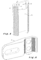
- Figure 5 shows a first embodiment of the rail 11 in greater detail.
- the rail shown consists of a folded metal (iron) strip and is simply obtained by folding a flat metal strip along two parallel fold lines.
- the flanks 13 of the rail extend virtually from the bottom 12 of the rail 11 at the same angle ⁇ relative to the bottom as the angle á formed by the part of the flanks which is clamped between the fixing element 8 and the sliding piece 10.
- the angle ⁇ in this case preferably lies between 15 and 75°, and most preferably between 25 and 65°. In the embodiment shown the angle ⁇ is, for example, approximately 45°.
- the bevelled parts 15 of the fixing element 8 and the parts of the flanks 13 of the rail 11 against which said bevelled parts 15 are clamped are provided with interlocking surface structures, in particular with a rib structure (see Figures 5 and 6).
- a surface structure could also be provided, if desired, on the bevelled parts 15 of the sliding piece 10 and on the inside of the flanks 13.
- a rail 11 is provided for each hinge.
- one longer rail 11 can also be provided on the gate, which rail extends, for example, over the full height of the gate, and is formed, for example, by a section of the gate itself, in such a way that two or more hinges can be fixed on it.
- the rail or rails can be fixed on the gate by means of, for example, screws or rivets, but it is/they are preferably welded onto it in such a way that a sturdy fixing, which is durable in all weather conditions, is obtained.
- the rails are fixed with their bottom 12 against the side of the gate. This has the advantage that the gate with the rails fixed on it can be used either as a left-hand or as a right-hand gate. A further advantage is that the flanks of the rail will be pulled less quickly askew under the weight of the gate, and can therefore be made of a lighter design.
- the gate is preferably galvanized and/or lacquered.
- the gate is generally galvanized and subsequently subjected optionally to a powder coating process.
- the advantage of the hanging mechanism according to the invention in this case is that differences in thicknesses of the coatings applied in this way do not constitute any problem for the fitting of the sliding piece in the rail and for bolting the fixing element down on it.
- FIG. 7 to 10 A second possible embodiment of the mechanism according to the invention is shown in Figures 7 to 10.
- This embodiment differs in the main from the previous embodiment by the shape of the rail 11.
- This rail 11 consists of a piece which is cast or cut from metal. This has the advantage that the flanks can be made thicker, in order to increase the sturdiness in this way.
- the casting or cutting of the rail also makes it possible for the inside surface 21 and the outside surface 22 of the flanks 13 not to be made parallel to each other, and thus to form a different angle of inclination ⁇ with the bottom of the rail.
- This bottom is further formed by the side of the gate 1 or door against which the rail 11 is fixed, in particular is welded.
- the longitudinal slot 23 formed by the free ends of the flanks 13 directed towards each other is furthermore closed off at the top and bottom, in such a way that, should the bolts 7 possibly loosen slightly, the gate will always remain hanging on the support.
- the longitudinal edges of the rail 11 are further provided with a lip 24, which forms a stop for the fixing element 8 if the gate is opened too far, in such a way that further opening is prevented by the hinges. These stops prevent the fixing mechanism from being forced in that case by the great force of the opening gate.
- FIG 11 shows yet another variant embodiment, in which the fixing element 8 is not a separate element, but is a part of the hinge itself.
- the fixing element 8 in this case forms a joint by means of which the gate can be hooked on a pin 17 of the second hinge part 18.
- This embodiment is primarily of interest for hanging the gate on a wall or on a broader, generally brickwork post.
- the second hinge part 18 is provided with a plate part 19 for bolting to the wall or the post, and having longitudinal openings 20 for the screws, in such a way that some vertical adjustment of the gate is possible.
- a vertical adjustment in this case in one direction, more particularly in the plane of the post or the wall, is adequate.
- the two flanks of the rail and the parts of the sliding piece and the fixing element clamped against them can be disposed at a different angle ⁇ .
- the same fixing element consisting of the rail, the sliding piece and the fixing element which can be bolted down on it can also be provided on the support, so that the height of the gate could be adjusted by adjusting the height of the hinge part fixed on the support.
- Such an adjusting mechanism with rail, sliding piece and fixing element could replace the adjusting mechanism on the gate, but can also be used on the gate in combination with the adjusting mechanism described above, in order to permit additional adjusting possibilities in this way.
Landscapes
- Engineering & Computer Science (AREA)
- Mechanical Engineering (AREA)
- Hinges (AREA)
- Gates (AREA)
- Load-Engaging Elements For Cranes (AREA)
- Spinning Or Twisting Of Yarns (AREA)
- Automotive Seat Belt Assembly (AREA)
Claims (15)
- Einrichtung zur Aufhängung eines Tores (1) oder einer Tür durch ein Scharnier auf verstellbarer Höhe auf einem Träger (3), wobei die Einrichtung zumindest eine muldenförmige Schiene (11) umfasst, welche am Träger (3) und/oder am Tor (1) oder an der Tür angebracht ist und einen Boden (12) und zwei Seitenflächen (13), ein Schiebeteil (10), das vertikal in der Schiene (11) verschoben werden kann, und ein Befestigungselement (8) hat, das auf das erwähnte Schiebeteil geschraubt werden kann, um das Scharnier (2, 4, 5) auf der Schiene zu befestigen, wobei zumindest ein Teil jeder der Seitenflächen (13) der Schiene (11) einander zugewendet sind und so angebracht sind, dass sie, wenn das Befestigungselement (8) auf das Schiebeteil (10) geschraubt wird, zwischen Teilen (15) des erwähnten Befestigungselements (8) und Teilen (14) des Schiebeteils (10) eingeklemmt werden, wobei die erwähnten Teile (15) des Befestigungselements (8) und die erwähnten Teile (14) des Schiebeteils (10) jeweils eine Oberfläche haben, durch die sie im montierten Zustand Kontakt mit dem Seitenteil haben, gegen das sie geklemmt werden, dadurch gekennzeichnet, dass die erwähnten Teile der Seitenflächen (13) jeweils eine Innenfläche (21) und eine Außenfläche (22) haben, die jeweils einen Neigungswinkel (α) mit dem Boden (12) der Schiene (11) bilden, und dadurch, dass die Kontaktflächen der erwähnten Teile (15) des Befestigungselements (8) und der erwähnten Teile (14) des Schiebeteils (10) in montiertem Zustand jeweils einen Winkel mit dem Boden der Schiene bilden, der praktisch gleich ist wie der Neigungswinkel (α), welcher durch die Innenfläche (21) oder Außenfläche (22) des Seitenteils gebildet wird, gegen das das erwähnte Teil (14 und/oder 15) geklemmt wird.
- Einrichtung nach Anspruch 1, dadurch gekennzeichnet, dass die Innenflächen (21) und die Außenflächen (22) der Seitenflächen (13) der Schiene (11) sich im erwähnten Neigungswinkel (α) praktisch vom Boden (12) der Schiene (11) zu dem Teil der Seitenflächen ausdehnen, der zum Klemmen zwischen dem Befestigungselement (8) und dem Schiebeteil (10) vorgesehen ist.
- Einrichtung nach Anspruch 1 oder 2, dadurch gekennzeichnet, dass die geklemmten Teile der Seitenflächen (13) mit einer Oberflächenstruktur ausgestattet sind und dass die Teile (14 und/oder 15) des Befestigungselements (8) und/oder des Schiebeteils (10), zwischen denen diese Teile der Seitenflächen (13) eingeklemmt werden, mit einer Oberflächenstruktur ausgestattet sind, die mit der oben angeführten Oberflächenstruktur interagiert, wobei diese Oberflächenstrukturen angebracht sind, um einer vertikalen Verschiebung des Befestigungselements (8) relativ zur Schiene (11) entgegen zu wirken, und vorzugsweise durch eine Rippenstruktur gebildet werden.
- Einrichtung nach einem der Ansprüche 1 bis 3, dadurch gekennzeichnet, dass die Innenflächen (21) der geklemmten Teile der beiden Seitenflächen (13) praktisch denselben Neigungswinkel (α) mit dem Boden (12) der Schiene (11) bilden, und/oder dadurch, dass die Außenflächen (22) der geklemmten Teile der beiden Seitenflächen (13) praktisch denselben Neigungswinkel (α) mit dem Boden (12) der Schiene (11) bilden.
- Einrichtung nach einem der Ansprüche 1 bis 4, dadurch gekennzeichnet, dass der erwähnte Neigungswinkel (α) zwischen 15 und 75° und vorzugsweise zwischen 25 und 65° liegt.
- Einrichtung nach einem der Ansprüche 1 bis 5, dadurch gekennzeichnet, dass die erwähnte Schiene (11) durch einen gefalteten Metallstreifen gebildet ist.
- Einrichtung nach Anspruch 6, dadurch gekennzeichnet, dass die Schiene (11) durch Falten eines flachen Metallstreifens entlang zweier paralleler Faltlinien erhalten wird, um den erwähnten Boden (12) und die zwei Seitenflächen (13) zu bilden, die sich vom Boden (12) ausstrecken.
- Einrichtung nach einem der Ansprüche 1 bis 7, dadurch gekennzeichnet, dass der Boden (12) der Schiene (11) durch den Träger (3) oder durch das Tor (1) oder die Tür gebildet ist, auf dem bzw. der die Schiene (11) angebracht ist.
- Einrichtung nach einem der Ansprüche 1 bis 8, dadurch gekennzeichnet, dass die Schiene (11) auf das Tor (1), die Tür oder den Träger (3) geschweißt ist.
- Einrichtung nach einem der Ansprüche 1 bis 9, dadurch gekennzeichnet, dass das Tor (1), die Tür oder der Träger (3) mit der daran angebrachten Schiene (11) verzinkt und/oder lackiert ist.
- Einrichtung nach einem der Ansprüche 1 bis 10, dadurch gekennzeichnet, dass das Befestigungselement (8) durch mindestens zwei Bolzen (7) auf das erwähnte Schiebeteil (10) geschraubt ist.
- Einrichtung nach einem der Ansprüche 1 bis 11, dadurch gekennzeichnet, dass das Scharnier zwei Teile umfasst, die gelenkig miteinander verbunden sind, wobei ein erstes Teil durch das erwähnte Befestigungselement (8) gebildet ist, das zum Festschrauben auf dem Schiebeteil (10) vorgesehen ist.
- Einrichtung nach einem der Ansprüche 1 bis 11, dadurch gekennzeichnet, dass die Schiene (11) auf dem erwähnten Tor (1) oder der Tür angebracht ist und dass das Scharnier zwei Teile (2, 4) umfasst, die gelenkig miteinander verbunden sind, wobei das erste Teil (4) davon zur Befestigung auf dem erwähnten Befestigungselement (8) durch Befestigungsmittel (6, 9) vorgesehen ist, die die Befestigung des ersten Scharnierteils (4) auf dem Befestigungselement (8) in unterschiedlichen Abständen vom Tor (1) oder von der Tür ermöglichen, welche senkrecht zur Ebene des erwähnten Tores oder der Tür gemessen werden, wobei die Befestigungsmittel insbesondere ein Schloss (9) umfassen, das im Befestigungselement (8) angebracht ist, wobei das erste Teil (4) des Scharniers in verschiedenen Positionen in diesem Schloss fixiert werden kann.
- Einrichtung nach einem der Ansprüche 1 bis 13, dadurch gekennzeichnet, dass die Schiene (11) auf dem Tor (1) oder der Tür angebracht ist, vorzugsweise auf einer Seite des erwähnten Tores oder der Tür.
- Set zur Befestigung auf einem Tor (1), einer Tür oder einem Träger (3), welches eine Schiene (11), ein Schiebeteil (10) zur Montage in der erwähnten Schiene und eine Einrichtung wie definiert in einem der vorigen Ansprüche umfasst.
Applications Claiming Priority (2)
| Application Number | Priority Date | Filing Date | Title |
|---|---|---|---|
| BE200300582 | 2003-10-31 | ||
| BE2003/0582A BE1015758A3 (nl) | 2003-10-31 | 2003-10-31 | Mechanisme voor het op een instelbare hoogte aan een steun ophangen van een poort. |
Publications (3)
| Publication Number | Publication Date |
|---|---|
| EP1528202A2 EP1528202A2 (de) | 2005-05-04 |
| EP1528202A3 EP1528202A3 (de) | 2005-07-13 |
| EP1528202B1 true EP1528202B1 (de) | 2006-08-30 |
Family
ID=34397928
Family Applications (1)
| Application Number | Title | Priority Date | Filing Date |
|---|---|---|---|
| EP04105458A Expired - Lifetime EP1528202B1 (de) | 2003-10-31 | 2004-11-02 | Einrichtung für eine höheneinstellbare Halterung eines Tores |
Country Status (4)
| Country | Link |
|---|---|
| EP (1) | EP1528202B1 (de) |
| AT (1) | ATE338187T1 (de) |
| BE (1) | BE1015758A3 (de) |
| DE (1) | DE602004002173T2 (de) |
Cited By (7)
| Publication number | Priority date | Publication date | Assignee | Title |
|---|---|---|---|---|
| EP2317048A1 (de) | 2009-10-30 | 2011-05-04 | Joseph Talpe | Einstellbare Scharnieranordnung |
| EP3342969A1 (de) | 2016-12-27 | 2018-07-04 | Locinox | Hydraulisch gedämpfter aktuator und selbstschliessendes scharnier mit dem aktuator |
| WO2018121890A1 (en) | 2016-12-27 | 2018-07-05 | Locinox | A hydraulically damped actuator |
| WO2018122210A1 (en) | 2016-12-27 | 2018-07-05 | Locinox | Hydraulically damped actuator and self-closing hinge comprising the actuator |
| WO2018228729A1 (en) | 2017-06-16 | 2018-12-20 | Locinox | A hydraulically damped actuator |
| WO2019048359A1 (en) | 2017-09-05 | 2019-03-14 | Locinox | DOOR CLOSURE DEVICE THAT CAN BE ADAPTED ON A DOOR WITH AN EYE BOLT HINGE |
| RU2772699C2 (ru) * | 2017-09-05 | 2022-05-24 | Локинокс | Закрывающий механизм для ворот, выполненный с возможностью установки на ворота с петлей с рым-болтом |
Families Citing this family (21)
| Publication number | Priority date | Publication date | Assignee | Title |
|---|---|---|---|---|
| NL2003464C2 (nl) * | 2008-09-11 | 2010-12-21 | Mauriks Group B V | Beveiligd scharnier voor de ophanging van poorten en deuren. |
| EP2431559A3 (de) * | 2010-09-21 | 2014-08-27 | VKR Holding A/S | Fensterflügelprofil mit verstellbarer Schiene mit begrenzter Länge |
| EP2778330B1 (de) | 2013-03-11 | 2015-08-12 | Locinox | Scharnieranordnung |
| EP2778331A1 (de) * | 2013-03-11 | 2014-09-17 | Joseph Talpe | Scharnieranordnung |
| CN103452407B (zh) * | 2013-09-11 | 2016-08-10 | 苏州岸肯电子科技有限公司 | 可调节高度的活页 |
| EP2862997B1 (de) | 2013-10-18 | 2016-10-05 | Joseph Talpe | Scharnieranordnung |
| DE102014110323B3 (de) * | 2014-07-22 | 2015-06-03 | Aos Stahl Gmbh & Co. Kg | Toranlage und Verfahren zur schwenkbaren Lagerung eines Torrahmens an einem Scharnierpfosten |
| RU2572175C1 (ru) * | 2014-09-09 | 2015-12-27 | Общество с ограниченной ответственностью "Дефенс-Рус" | Шарнир калиточный и воротный |
| EP3162996A1 (de) | 2015-10-30 | 2017-05-03 | Locinox | Vorrichtung zum verschliessen eines verschlusselements, das schwenkbar auf einem träger angeordnet ist |
| BE1025033B1 (nl) * | 2017-09-05 | 2018-10-03 | Locinox Nv | Oogboutscharnier en daarmee op steun bevestigde poort |
| KR20220168100A (ko) * | 2021-06-15 | 2022-12-22 | 엘지전자 주식회사 | 조리기기 |
| EP4400684A1 (de) | 2023-01-13 | 2024-07-17 | Locinox | Torschliesser und verschlusssystem damit |
| BE1032036B1 (nl) | 2023-10-05 | 2025-05-12 | Locinox Nv | Een poortactuator |
| WO2025073952A1 (en) | 2023-10-05 | 2025-04-10 | Locinox | A gate actuator |
| BE1032034B1 (nl) | 2023-10-05 | 2025-05-12 | Locinox Nv | Een poortactuator |
| BE1032121B1 (nl) | 2023-11-08 | 2025-06-10 | Locinox Nv | Een poortactuator |
| BE1032033B1 (nl) | 2023-10-05 | 2025-05-12 | Locinox Nv | Een poortactuator |
| EP4610468A1 (de) | 2024-03-01 | 2025-09-03 | Locinox | Torpfosten |
| EP4610454A1 (de) | 2024-03-01 | 2025-09-03 | Locinox | Torpfosten |
| EP4610453A1 (de) | 2024-03-01 | 2025-09-03 | Locinox | Torpfosten |
| EP4671486A1 (de) | 2024-06-25 | 2025-12-31 | Locinox | Torpfosten |
Family Cites Families (3)
| Publication number | Priority date | Publication date | Assignee | Title |
|---|---|---|---|---|
| GB618725A (en) * | 1946-11-20 | 1949-02-25 | Phillip Harwood | Improvements in an adjustable mounting for a pin for hanging a gate or door |
| NL1002994C2 (nl) * | 1996-05-03 | 1997-11-06 | Inoko B V I O | Kozijnconstructie. |
| ITTO20010420A1 (it) * | 2001-05-04 | 2002-11-04 | Savio Spa | Cerniera per porte, finestre e simili, destinata ad essere fissata a serramenti metallici. |
-
2003
- 2003-10-31 BE BE2003/0582A patent/BE1015758A3/nl not_active IP Right Cessation
-
2004
- 2004-11-02 EP EP04105458A patent/EP1528202B1/de not_active Expired - Lifetime
- 2004-11-02 AT AT04105458T patent/ATE338187T1/de not_active IP Right Cessation
- 2004-11-02 DE DE602004002173T patent/DE602004002173T2/de not_active Expired - Lifetime
Cited By (8)
| Publication number | Priority date | Publication date | Assignee | Title |
|---|---|---|---|---|
| EP2317048A1 (de) | 2009-10-30 | 2011-05-04 | Joseph Talpe | Einstellbare Scharnieranordnung |
| EP3342969A1 (de) | 2016-12-27 | 2018-07-04 | Locinox | Hydraulisch gedämpfter aktuator und selbstschliessendes scharnier mit dem aktuator |
| WO2018121890A1 (en) | 2016-12-27 | 2018-07-05 | Locinox | A hydraulically damped actuator |
| WO2018122210A1 (en) | 2016-12-27 | 2018-07-05 | Locinox | Hydraulically damped actuator and self-closing hinge comprising the actuator |
| WO2018228729A1 (en) | 2017-06-16 | 2018-12-20 | Locinox | A hydraulically damped actuator |
| EP4249718A2 (de) | 2017-06-16 | 2023-09-27 | Locinox | Hydraulisch gedämpfter aktuator |
| WO2019048359A1 (en) | 2017-09-05 | 2019-03-14 | Locinox | DOOR CLOSURE DEVICE THAT CAN BE ADAPTED ON A DOOR WITH AN EYE BOLT HINGE |
| RU2772699C2 (ru) * | 2017-09-05 | 2022-05-24 | Локинокс | Закрывающий механизм для ворот, выполненный с возможностью установки на ворота с петлей с рым-болтом |
Also Published As
| Publication number | Publication date |
|---|---|
| EP1528202A3 (de) | 2005-07-13 |
| DE602004002173D1 (de) | 2006-10-12 |
| DE602004002173T2 (de) | 2007-07-19 |
| EP1528202A2 (de) | 2005-05-04 |
| BE1015758A3 (nl) | 2005-08-02 |
| ATE338187T1 (de) | 2006-09-15 |
Similar Documents
| Publication | Publication Date | Title |
|---|---|---|
| EP1528202B1 (de) | Einrichtung für eine höheneinstellbare Halterung eines Tores | |
| US6557303B2 (en) | Housing for automatic door mechanisms | |
| US5235724A (en) | Roller-hinge assembly for retractable overhead door | |
| US5375383A (en) | Garage door frame | |
| US4513554A (en) | Barn door framing system | |
| US7257864B2 (en) | Casement window hinge | |
| US20050115173A1 (en) | Roof scuttle safety railing system | |
| US20120102674A1 (en) | adjustable hinge | |
| US4438597A (en) | Adjustable hinge mount | |
| US4934439A (en) | Tension strut apparatus and method for an overhead garage door | |
| US4513555A (en) | Barn door framing system | |
| US4513535A (en) | Barn door framing system | |
| US20050273976A1 (en) | Adjustable roller bracket device for retractable door hinge | |
| US20090044377A1 (en) | Casement window hinge | |
| CZ53695A3 (en) | Connecting element for panels coupled with each other | |
| US20240200391A1 (en) | Door-ready molding | |
| US3265118A (en) | Overhead door retaining means | |
| PL231737B1 (pl) | Układ zawiasowy, a zwłaszcza układ zawiasu ukrytego | |
| US7454815B2 (en) | Coupling device | |
| AU2005100627A4 (en) | Security Grill | |
| GB2310239A (en) | Compound frame with adjustable side and top frame members. | |
| AU739178B2 (en) | Adjustable pivots for folding panels | |
| AU726943B3 (en) | Combination carrier and hinge for folding panels | |
| AU2006200002B1 (en) | An Adjustable in-Wall Cavity Sliding Door Frame Assembly | |
| US20120246876A1 (en) | Adjustable hinge |
Legal Events
| Date | Code | Title | Description |
|---|---|---|---|
| PUAI | Public reference made under article 153(3) epc to a published international application that has entered the european phase |
Free format text: ORIGINAL CODE: 0009012 |
|
| AK | Designated contracting states |
Kind code of ref document: A2 Designated state(s): AT BE BG CH CY CZ DE DK EE ES FI FR GB GR HU IE IS IT LI LU MC NL PL PT RO SE SI SK TR |
|
| AX | Request for extension of the european patent |
Extension state: AL HR LT LV MK YU |
|
| PUAL | Search report despatched |
Free format text: ORIGINAL CODE: 0009013 |
|
| AK | Designated contracting states |
Kind code of ref document: A3 Designated state(s): AT BE BG CH CY CZ DE DK EE ES FI FR GB GR HU IE IS IT LI LU MC NL PL PT RO SE SI SK TR |
|
| AX | Request for extension of the european patent |
Extension state: AL HR LT LV MK YU |
|
| 17P | Request for examination filed |
Effective date: 20051205 |
|
| GRAP | Despatch of communication of intention to grant a patent |
Free format text: ORIGINAL CODE: EPIDOSNIGR1 |
|
| AKX | Designation fees paid |
Designated state(s): AT BE BG CH CY CZ DE DK EE ES FI FR GB GR HU IE IS IT LI LU MC NL PL PT RO SE SI SK TR |
|
| GRAS | Grant fee paid |
Free format text: ORIGINAL CODE: EPIDOSNIGR3 |
|
| GRAA | (expected) grant |
Free format text: ORIGINAL CODE: 0009210 |
|
| AK | Designated contracting states |
Kind code of ref document: B1 Designated state(s): AT BE BG CH CY CZ DE DK EE ES FI FR GB GR HU IE IS IT LI LU MC NL PL PT RO SE SI SK TR |
|
| PG25 | Lapsed in a contracting state [announced via postgrant information from national office to epo] |
Ref country code: CZ Free format text: LAPSE BECAUSE OF FAILURE TO SUBMIT A TRANSLATION OF THE DESCRIPTION OR TO PAY THE FEE WITHIN THE PRESCRIBED TIME-LIMIT Effective date: 20060830 Ref country code: AT Free format text: LAPSE BECAUSE OF FAILURE TO SUBMIT A TRANSLATION OF THE DESCRIPTION OR TO PAY THE FEE WITHIN THE PRESCRIBED TIME-LIMIT Effective date: 20060830 Ref country code: CH Free format text: LAPSE BECAUSE OF FAILURE TO SUBMIT A TRANSLATION OF THE DESCRIPTION OR TO PAY THE FEE WITHIN THE PRESCRIBED TIME-LIMIT Effective date: 20060830 Ref country code: PL Free format text: LAPSE BECAUSE OF FAILURE TO SUBMIT A TRANSLATION OF THE DESCRIPTION OR TO PAY THE FEE WITHIN THE PRESCRIBED TIME-LIMIT Effective date: 20060830 Ref country code: IS Free format text: LAPSE BECAUSE OF FAILURE TO SUBMIT A TRANSLATION OF THE DESCRIPTION OR TO PAY THE FEE WITHIN THE PRESCRIBED TIME-LIMIT Effective date: 20060830 Ref country code: FI Free format text: LAPSE BECAUSE OF FAILURE TO SUBMIT A TRANSLATION OF THE DESCRIPTION OR TO PAY THE FEE WITHIN THE PRESCRIBED TIME-LIMIT Effective date: 20060830 Ref country code: LI Free format text: LAPSE BECAUSE OF FAILURE TO SUBMIT A TRANSLATION OF THE DESCRIPTION OR TO PAY THE FEE WITHIN THE PRESCRIBED TIME-LIMIT Effective date: 20060830 Ref country code: IT Free format text: LAPSE BECAUSE OF FAILURE TO SUBMIT A TRANSLATION OF THE DESCRIPTION OR TO PAY THE FEE WITHIN THE PRESCRIBED TIME-LIMIT;WARNING: LAPSES OF ITALIAN PATENTS WITH EFFECTIVE DATE BEFORE 2007 MAY HAVE OCCURRED AT ANY TIME BEFORE 2007. THE CORRECT EFFECTIVE DATE MAY BE DIFFERENT FROM THE ONE RECORDED. Effective date: 20060830 Ref country code: SI Free format text: LAPSE BECAUSE OF FAILURE TO SUBMIT A TRANSLATION OF THE DESCRIPTION OR TO PAY THE FEE WITHIN THE PRESCRIBED TIME-LIMIT Effective date: 20060830 Ref country code: RO Free format text: LAPSE BECAUSE OF FAILURE TO SUBMIT A TRANSLATION OF THE DESCRIPTION OR TO PAY THE FEE WITHIN THE PRESCRIBED TIME-LIMIT Effective date: 20060830 Ref country code: SK Free format text: LAPSE BECAUSE OF FAILURE TO SUBMIT A TRANSLATION OF THE DESCRIPTION OR TO PAY THE FEE WITHIN THE PRESCRIBED TIME-LIMIT Effective date: 20060830 |
|
| REG | Reference to a national code |
Ref country code: GB Ref legal event code: FG4D |
|
| REG | Reference to a national code |
Ref country code: CH Ref legal event code: EP |
|
| REG | Reference to a national code |
Ref country code: IE Ref legal event code: FG4D |
|
| REF | Corresponds to: |
Ref document number: 602004002173 Country of ref document: DE Date of ref document: 20061012 Kind code of ref document: P |
|
| PG25 | Lapsed in a contracting state [announced via postgrant information from national office to epo] |
Ref country code: IE Free format text: LAPSE BECAUSE OF NON-PAYMENT OF DUE FEES Effective date: 20061102 |
|
| PG25 | Lapsed in a contracting state [announced via postgrant information from national office to epo] |
Ref country code: DK Free format text: LAPSE BECAUSE OF FAILURE TO SUBMIT A TRANSLATION OF THE DESCRIPTION OR TO PAY THE FEE WITHIN THE PRESCRIBED TIME-LIMIT Effective date: 20061130 Ref country code: BG Free format text: LAPSE BECAUSE OF FAILURE TO SUBMIT A TRANSLATION OF THE DESCRIPTION OR TO PAY THE FEE WITHIN THE PRESCRIBED TIME-LIMIT Effective date: 20061130 Ref country code: MC Free format text: LAPSE BECAUSE OF NON-PAYMENT OF DUE FEES Effective date: 20061130 Ref country code: SE Free format text: LAPSE BECAUSE OF FAILURE TO SUBMIT A TRANSLATION OF THE DESCRIPTION OR TO PAY THE FEE WITHIN THE PRESCRIBED TIME-LIMIT Effective date: 20061130 |
|
| PG25 | Lapsed in a contracting state [announced via postgrant information from national office to epo] |
Ref country code: ES Free format text: LAPSE BECAUSE OF FAILURE TO SUBMIT A TRANSLATION OF THE DESCRIPTION OR TO PAY THE FEE WITHIN THE PRESCRIBED TIME-LIMIT Effective date: 20061211 |
|
| PG25 | Lapsed in a contracting state [announced via postgrant information from national office to epo] |
Ref country code: PT Free format text: LAPSE BECAUSE OF FAILURE TO SUBMIT A TRANSLATION OF THE DESCRIPTION OR TO PAY THE FEE WITHIN THE PRESCRIBED TIME-LIMIT Effective date: 20070206 |
|
| REG | Reference to a national code |
Ref country code: CH Ref legal event code: PL |
|
| ET | Fr: translation filed | ||
| PLBE | No opposition filed within time limit |
Free format text: ORIGINAL CODE: 0009261 |
|
| STAA | Information on the status of an ep patent application or granted ep patent |
Free format text: STATUS: NO OPPOSITION FILED WITHIN TIME LIMIT |
|
| 26N | No opposition filed |
Effective date: 20070531 |
|
| PG25 | Lapsed in a contracting state [announced via postgrant information from national office to epo] |
Ref country code: GR Free format text: LAPSE BECAUSE OF FAILURE TO SUBMIT A TRANSLATION OF THE DESCRIPTION OR TO PAY THE FEE WITHIN THE PRESCRIBED TIME-LIMIT Effective date: 20061201 |
|
| PG25 | Lapsed in a contracting state [announced via postgrant information from national office to epo] |
Ref country code: EE Free format text: LAPSE BECAUSE OF FAILURE TO SUBMIT A TRANSLATION OF THE DESCRIPTION OR TO PAY THE FEE WITHIN THE PRESCRIBED TIME-LIMIT Effective date: 20060830 |
|
| PG25 | Lapsed in a contracting state [announced via postgrant information from national office to epo] |
Ref country code: LU Free format text: LAPSE BECAUSE OF NON-PAYMENT OF DUE FEES Effective date: 20061102 Ref country code: TR Free format text: LAPSE BECAUSE OF FAILURE TO SUBMIT A TRANSLATION OF THE DESCRIPTION OR TO PAY THE FEE WITHIN THE PRESCRIBED TIME-LIMIT Effective date: 20060830 Ref country code: HU Free format text: LAPSE BECAUSE OF FAILURE TO SUBMIT A TRANSLATION OF THE DESCRIPTION OR TO PAY THE FEE WITHIN THE PRESCRIBED TIME-LIMIT Effective date: 20070301 |
|
| PG25 | Lapsed in a contracting state [announced via postgrant information from national office to epo] |
Ref country code: CY Free format text: LAPSE BECAUSE OF FAILURE TO SUBMIT A TRANSLATION OF THE DESCRIPTION OR TO PAY THE FEE WITHIN THE PRESCRIBED TIME-LIMIT Effective date: 20060830 |
|
| REG | Reference to a national code |
Ref country code: FR Ref legal event code: PLFP Year of fee payment: 12 |
|
| REG | Reference to a national code |
Ref country code: FR Ref legal event code: PLFP Year of fee payment: 13 |
|
| REG | Reference to a national code |
Ref country code: FR Ref legal event code: PLFP Year of fee payment: 14 |
|
| REG | Reference to a national code |
Ref country code: FR Ref legal event code: PLFP Year of fee payment: 15 |
|
| PGFP | Annual fee paid to national office [announced via postgrant information from national office to epo] |
Ref country code: NL Payment date: 20231013 Year of fee payment: 20 |
|
| PGFP | Annual fee paid to national office [announced via postgrant information from national office to epo] |
Ref country code: GB Payment date: 20231121 Year of fee payment: 20 |
|
| PGFP | Annual fee paid to national office [announced via postgrant information from national office to epo] |
Ref country code: FR Payment date: 20231013 Year of fee payment: 20 Ref country code: DE Payment date: 20231127 Year of fee payment: 20 |
|
| PGFP | Annual fee paid to national office [announced via postgrant information from national office to epo] |
Ref country code: BE Payment date: 20231013 Year of fee payment: 20 |
|
| REG | Reference to a national code |
Ref country code: DE Ref legal event code: R071 Ref document number: 602004002173 Country of ref document: DE |
|
| REG | Reference to a national code |
Ref country code: NL Ref legal event code: MK Effective date: 20241101 |
|
| REG | Reference to a national code |
Ref country code: GB Ref legal event code: PE20 Expiry date: 20241101 |
|
| REG | Reference to a national code |
Ref country code: BE Ref legal event code: MK Effective date: 20241102 |
|
| PG25 | Lapsed in a contracting state [announced via postgrant information from national office to epo] |
Ref country code: GB Free format text: LAPSE BECAUSE OF EXPIRATION OF PROTECTION Effective date: 20241101 |
|
| PG25 | Lapsed in a contracting state [announced via postgrant information from national office to epo] |
Ref country code: GB Free format text: LAPSE BECAUSE OF EXPIRATION OF PROTECTION Effective date: 20241101 |