EP1528151A2 - Rail fastening assembly - Google Patents
Rail fastening assembly Download PDFInfo
- Publication number
- EP1528151A2 EP1528151A2 EP04405053A EP04405053A EP1528151A2 EP 1528151 A2 EP1528151 A2 EP 1528151A2 EP 04405053 A EP04405053 A EP 04405053A EP 04405053 A EP04405053 A EP 04405053A EP 1528151 A2 EP1528151 A2 EP 1528151A2
- Authority
- EP
- European Patent Office
- Prior art keywords
- guide plate
- toothing
- rail
- counter
- track
- Prior art date
- Legal status (The legal status is an assumption and is not a legal conclusion. Google has not performed a legal analysis and makes no representation as to the accuracy of the status listed.)
- Granted
Links
Images


Classifications
-
- E—FIXED CONSTRUCTIONS
- E01—CONSTRUCTION OF ROADS, RAILWAYS, OR BRIDGES
- E01B—PERMANENT WAY; PERMANENT-WAY TOOLS; MACHINES FOR MAKING RAILWAYS OF ALL KINDS
- E01B9/00—Fastening rails on sleepers, or the like
- E01B9/38—Indirect fastening of rails by using tie-plates or chairs; Fastening of rails on the tie-plates or in the chairs
- E01B9/58—Fastening the rail in the chair
Definitions
- the invention relates to a fastening arrangement for rails, with at least one Guide plate, which with a clamping device on a top of a track stool fixed and slidable relative to a rail foot, said upper side of the track stool has a toothing, in which a counter toothing on a Bottom of the guide plate engages and thereby the rails against a lateral Shift fixed.
- track gauge errors for example, due to rolling tolerances of the rails, only very roughly balanced can be. Corrections of the track are possible per se, but very complex and in not suitable for practice. For example, track corrections are by inserting Distance plates between the guide plate and the rail foot possible. Such Spacer plates are however prone to corrosion.
- the invention is based on the object, a fastening arrangement of the type mentioned to create, which allows finer track corrections and for different Rails and in particular rail foot widths. A toe correction should also after be possible to cast in the track stool.
- the object is achieved in a generic mounting arrangement characterized in that the guide plate has two lateral abutment surfaces and is rotatable by 180 degrees and that said counter-toothing is offset so that by rotating the guide plate by 180 degrees the track gauge by an amount smaller than the tooth spacing of the said gearing is correctable.
- the fastening arrangement 1 shown in FIGS. 4 and 5 has a concrete to be incorporated Track stool 3, which is in particular a casting and the top 5 with has two teeth 4.
- the two teeth 4 are provided with an area 26 of separated, in which the top 5 is flat and thus not interlocked. in the Region 26 is a here merely indicated rail 2.
- the teeth 4 are formed by ribs 27 which are parallel to each other and parallel to the to be fastened Rail 2 run, as the figure 5 reveals.
- the rail 2 to be fastened is in particular a grooved grooved rail or Vignol rail. This is supported in the area 26 on the track stool 3 with a foot 13.
- the foot 13 can be different widths and in particular the rail foot width can be different be.
- To attach the rail 2 are opposite to each one Guide plate 15 created. These two guide plates 15 point at an underside 17 each have a counter toothing 16, which in the assembled state with the toothing 4 combs.
- the counter-toothing 16 is also formed by parallel ribs 22 and 23 ( Figure 6).
- the tooth spacings of the teeth 4 and 16 are the same. These be for example 4 mm.
- the plates 15 are each suitable with a clamping device or another suitable Mounting arrangement on the track stool 3 releasably attached.
- the clamping device 7 For example, according to Figures 4 and 5, a hook screw 8, which with a Hook 9 in a groove 6 of a guide plate 15 is slidably mounted. On the free upper end of the hook screw 8 are a washer 11 and a nut 10th attached, with which a mounting bracket 12 under tension to the foot 13 and at a top 18 is pressed against the guide plate 15.
- the known Mounting bracket 12 is made of a bar steel in the form of a W and is located elastically on the rail foot 13 and in a recess 29 on the guide plate 15 at. It But here are other suitable fasteners conceivable here used could become. One of these will be explained below with reference to FIG. For sound insulation is between the foot 13 and the track frame 3 an insulation mat 25th arranged.
- the attachment plates 15 each have oppositely laterally open slots 21 on, which are optionally used for receiving the hook screw 8.
- the one of the two slots 21 is not visible, because he from the hook screw 8 is covered.
- the guide plate 15 are rotated 180 degrees in their horizontal plane, so now the other Slot 21 receives the shank of the hook screw 8.
- the two guide plates 15 can be moved after loosening the corresponding nuts 10 on the track stool 3 become. This shifting takes place stepwise according to the one shown in FIG Distance D1 of the toothing 4 or counter toothing 16. By this displacement can the two guide plates 15 each optionally with a stop surface 19 and 20 are applied to the narrow side 14 of the rail foot 13 shown in FIG.
- the two guide plates 15 independently of each other by 180 Degrees are turned.
- an embodiment is conceivable in which only the a guide plate 15 has an offset counter-toothing 16.
- After setting in concrete the track stool 3 and the laying of the rail 2 is thus at a later date even a correction of, for example, 2 mm possible, with only the guide plate 15 must be rotated 180 degrees.
- the comparatively large tooth spacing of 4 mm has the advantage that the guide plates 15 as before can be produced inexpensively by forging. It results This also causes a little pollution-prone positive connection between the track stool 3 and the guide plate 15. After mounting the Fastening arrangement covered with concrete, it is thus in the so-called Under concrete area. Possible are full insulation as well as a mounting in conventional Track installation. As already mentioned, different tracked rails 2 can be used become.
- FIG. 7 shows a fastening arrangement in which a guide plate 30 is used, in which the top 31 may be flat.
- the guide plate 30 is in Distance to the rail 2 arranged on the track stool 3.
- a projection 33 of a bearing part 34 the made of an insulating plastic.
- the projection 33 is located on the guide plate 30th and on the rail 2 and has a vertically extending passage 35, which the Hook screw 8 receives, which biases a spring tension plate 36 down and thereby presses the bearing part 34 on the guide plate 30 and on the rail 2.
- a Cover 37 made of plastic forms a protection and is detachably mounted from above.
- the known per se bearing part 34 is with different width approaches 33rd available.
- the width varies at intervals of 2.5 and 2 mm.
- the available widths For example, 45 mm, 47.5 mm 50 mm and 52.5 mm.
- the invention thus allows for different types of attachment without major Expense a much finer correction of the track gauge and thereby can the Tracking the rails 2 are better respected.
Landscapes
- Engineering & Computer Science (AREA)
- Mechanical Engineering (AREA)
- Architecture (AREA)
- Civil Engineering (AREA)
- Structural Engineering (AREA)
- Connection Of Plates (AREA)
- Seats For Vehicles (AREA)
- Machines For Laying And Maintaining Railways (AREA)
- Braking Arrangements (AREA)
- Portable Nailing Machines And Staplers (AREA)
- Railway Tracks (AREA)
- Escalators And Moving Walkways (AREA)
- Warehouses Or Storage Devices (AREA)
- Linear Motors (AREA)
Abstract
Die Befestigungsanordnung weist wenigstens eine Führungsplatte (15) auf, die mit einer
Klemmvorrichtung (7) auf einer Oberseite (5) eines Gleisschemels (3) fon-nschlüssig
befestigt und gegen einen Schienenfuss (13) schiebbar ist. Die genannte Oberseite (5) des
Gleisschemels (3) besitzt eine Verzahnung (4), in die eine Gegenverzahnung (16) an einer
Unterseite (17) der Führungsplatte (15) eingreift und dadurch die Schiene (2) gegen eine
seitliche Verschiebung fixiert. Die Führungsplatte (15) besitzt zwei seitliche Anschlagflächen
(19, 20) und ist um 180 Grad drehbar. Die genannte Gegenverzahnung (16) ist
versetzt, sodass durch Drehen der Führungsplatte (15) um 180 Grad das Spurmass (S1, S2)
um einen Betrag kleiner als der Zahnabstand (D1) der genannten Verzahnung (16)
kon-igierbar ist.
Description
Die Erfindung betrifft eine Befestigungsanordnung für Schienen, mit wenigstens einer Führungsplatte, die mit einer Klemmvorrichtung auf einer Oberseite eines Gleisschemels befestigt und relativ zu einem Schienenfuss verschiebbar ist, wobei die genannte Oberseite des Gleisschemels eine Verzahnung aufweist, in die eine Gegenverzahnung an einer Unterseite der Führungsplatte eingreift und dadurch die Schienen gegen eine seitliche Verschiebung fixiert.The invention relates to a fastening arrangement for rails, with at least one Guide plate, which with a clamping device on a top of a track stool fixed and slidable relative to a rail foot, said upper side of the track stool has a toothing, in which a counter toothing on a Bottom of the guide plate engages and thereby the rails against a lateral Shift fixed.
Im Stand der Technik sind bereits zahlreiche Befestigungsarten zum Verankern von gespurten Rillen- oder Vignolschienen bekannt geworden. Werden bei einer solchen Befestigungsanordnung Gleisschemel verwendet, so können gespurte Schienen ohne Betonschwellen oder ähnlichen Verbindungselementen montiert werden. Bei einer solchen Befestigungsanordnung ist eine weitgehende Schallisolierung möglich. Im Stand der Technik ist auch eine Befestigungsanordnung bekannt, bei welcher der Gleisschemel an seiner Oberseite eine Verzahnung mit parallelen Rippen aufweist, mit welcher eine Führungsplatte fixiert wird, die eine Gegenverzahnung besitzt. Die Führungsplatte ist so verschiebbar, dass sie an den Schienenfuss anlegbar ist. Mit einer Hakenschraube und einer Befestigungsklammer wird die an den Schienenfuss angelegte Führungsplatte auf dem Gleisschemel fixiert. In der Regel werden zwei Führungsplatten verwendet, die jeweils an einer Seite der Schiene anzulegen sind. In the prior art are already numerous types of attachment for anchoring grooved grooves or Vignole rails become known. Be with such Used mounting rail track, so can be tracked rails without Concrete sleepers or similar fasteners are mounted. In such a Mounting arrangement is a substantial sound insulation possible. In the state of Technique is also known a mounting arrangement, wherein the track stool to its upper side has a toothing with parallel ribs, with which a Guide plate is fixed, which has a counter-toothing. The guide plate is like that slidable that it can be applied to the rail foot. With a hook screw and a Clamp is the applied to the rail foot guide plate on the Track stool fixed. In general, two guide plates are used, each one on one side of the rail are to create.
Bei den bekannten Befestigungsanordnungen besteht die Schwierigkeit, dass Spurmassfehler, beispielsweise aufgrund von Walztoleranzen der Schienen, nur sehr grob ausgeglichen werden können. Korrekturen der Spur sind an sich möglich, jedoch sehr aufwändig und in der Praxis nicht geeignet. Beispielsweise sind Spurkorrekturen durch Einlegen von Distanzplatten zwischen der Führungsplatte und dem Schienenfuss möglich. Solche Distanzplatten sind jedoch korrisionsanfällig.In the known mounting arrangements, there is the difficulty that track gauge errors, for example, due to rolling tolerances of the rails, only very roughly balanced can be. Corrections of the track are possible per se, but very complex and in not suitable for practice. For example, track corrections are by inserting Distance plates between the guide plate and the rail foot possible. Such Spacer plates are however prone to corrosion.
Der Erfindung liegt die Aufgabe zugrunde, eine Befestigungsanordnung der genannten Art zu schaffen, welche feinere Spurkorrekturen ermöglicht und die sich für unterschiedliche Schienen und insbesondere Schienenfussbreiten eignet. Eine Spurkorrektur soll auch nach dem Einbetonieren des Gleisschemels möglich sein.The invention is based on the object, a fastening arrangement of the type mentioned to create, which allows finer track corrections and for different Rails and in particular rail foot widths. A toe correction should also after be possible to cast in the track stool.
Die Aufgabe ist bei einer gattungsgemässen Befestigungsanordnung dadurch gelöst, dass die Führungsplatte zwei seitliche Anschlagflächen aufweist und um 180 Grad drehbar ist und dass die genannte Gegenverzahnung versetzt ist, sodass durch Drehen der Führungsplatte um 180 Grad das Spurmass um einen Betrag kleiner als der Zahnabstand der genannten Verzahnung korrigierbar ist.The object is achieved in a generic mounting arrangement characterized in that the guide plate has two lateral abutment surfaces and is rotatable by 180 degrees and that said counter-toothing is offset so that by rotating the guide plate by 180 degrees the track gauge by an amount smaller than the tooth spacing of the said gearing is correctable.
Bei der erfindungsgemässen Befestigungsanordnung können beispielsweise allgemeine Walztoleranzen der Schienen feiner als bisher korrigiert werden. Eine Korrektur ist auch nach dem Einbetonieren des Gleisschemels möglich. Bei der erfindungsgemässen Befestigungsanordnung können die bisher verwendeten Gleisschemel verwendet werden. Die Verzahnung des Gleisschemels und die Gegenverzahnung der Führungsplatten können den bisher verwendeten Zahnabstand von beispielsweise 4 mm aufweisen. Eine solche Verzahnung ist vergleichsweise wenig verschmutzungs- und korrosionsanfällig. Mit der erfindungsgemässen Befestigungsanordnung können beispielsweise Spurfehler um 2 mm korrigiert werden. Hierzu ist es lediglich erforderlich, dass die Führungsplatte um 180 Grad gedreht wird. Die Erfindung ermöglicht somit eine feinere Spurkorrektur ohne zusätzliche Teile und ohne die Montage aufwändiger zu gestalten. Die durch die Erfindung ermöglichte Feinkorrektur hat die folgenden wesentlichen Vorteile:
- Durch die kleineren Spurfehler kann der Verschleiss an Schiene und Rad wesentlich vermindert werden.
- Die Fahrruhe und auch der Fahrkomfort können wesentlich verbessert werden.
- Kurven werden weniger ausgefahren und der notwendige Unterhalt verursacht kleinere Kosten.
- Due to the smaller tracking errors, the wear on the rail and wheel can be significantly reduced.
- The smoothness and the ride comfort can be significantly improved.
- Curves are less extended and the necessary maintenance costs less.
Weitere vorteilhafte Merkmale ergeben sich aus den abhängigen Patentansprüchen, der nachfolgenden Beschreibung sowie der Zeichnung.Further advantageous features emerge from the dependent claims, the following description and the drawing.
Ein Ausführungsbeispiel der Erfindung wird nachfolgend anhand der Zeichnung näher erläutert. Es zeigen:
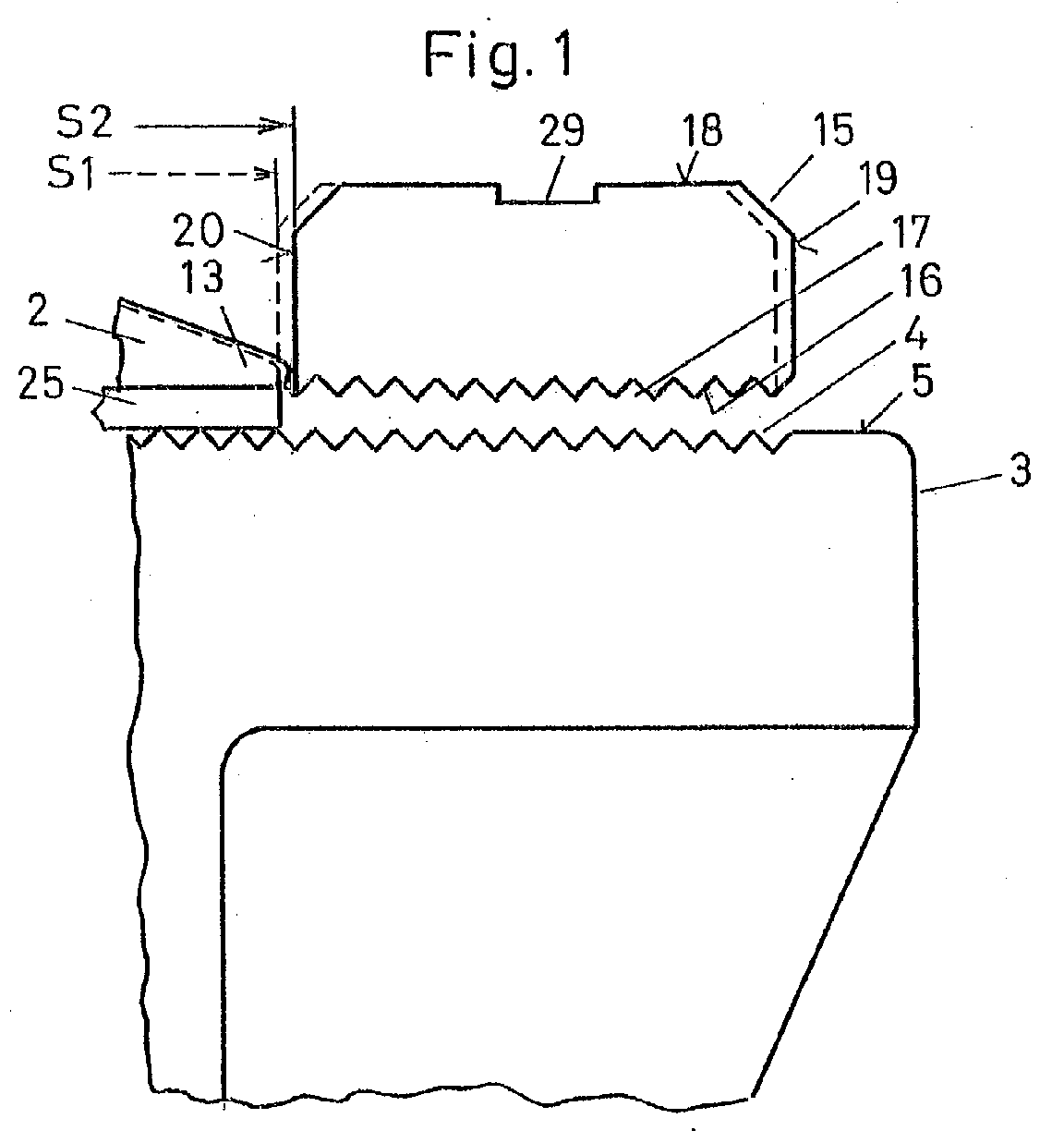
Figur 1- schematisch eine Teilansicht der erfindungsgemässen Befestigungsanordnung, wobei die Führungsplatte aus zeichnerischen Gründen abgehoben und Teile weggelassen sind,
Figur 2- eine Ansicht eines Gleisschemels,
Figur 3- eine weitere Ansicht des Gleisschemels,
Figur 4- ein Vertikalschnitt durch eine erfindungsgemässe Befestigungsanordnung mit einer Führungsplatte nach einer Variante,
Figur 5- eine Draufsicht auf die erfindungsgemässe Befestigungsanordnung nach
Figur 4, Figur 6- schematisch ein Abschnitt der erfindungsgemässen Befestigungsanordnung zu einer Station der Ausbildung der Verzahnung und Gegenverzahnung und
- Figur 7
- schematisch ein Teilschnitt durch eine Befestigungsanordnung nach einer weiteren Variante.
- FIG. 1
- 1 is a schematic partial view of the fastening arrangement according to the invention, the guide plate being lifted off for reasons of drawing and parts being omitted,
- FIG. 2
- a view of a track stool,
- FIG. 3
- another view of the track stool,
- FIG. 4
- 3 a vertical section through a fastening arrangement according to the invention with a guide plate according to a variant,
- FIG. 5
- a top view of the inventive fastening arrangement according to Figure 4,
- FIG. 6
- schematically a portion of the inventive fastening arrangement to a station of the formation of the teeth and counter teeth and
- FIG. 7
- schematically a partial section through a mounting arrangement according to another variant.
Die in den Figuren 4 und 5 gezeigte Befestigungsanordnung 1 weist einen einzubetonierenden
Gleisschemel 3 auf, der insbesondere ein Gussteil ist und der eine Oberseite 5 mit
zwei Verzahnungen 4 aufweist. Die beiden Verzahnungen 4 sind mit einem Bereich 26 von
einander getrennt, in welchen die Oberseite 5 eben und somit nicht verzahnt ist. Im
Bereich 26 liegt eine hier lediglich angedeutete Schiene 2 auf. Die Verzahnungen 4 werden
durch Rippen 27 gebildet, die parallel zueinander und parallel zu der zu befestigenden
Schiene 2 verlaufen, wie die Figur 5 erkennen lässt.The
Die zu befestigende Schiene 2 ist insbesondere eine gespurte Rillen- oder Vignolschiene.
Diese ist im Bereich 26 auf dem Gleisschemel 3 mit einem Fuss 13 abgestützt. Der Fuss 13
kann unterschiedlich breit sein und insbesondere kann die Schienenfussbreite unterschiedlich
sein. Zur Befestigung der Schiene 2 sind an diese gegenüberliegend jeweils eine
Führungsplatte 15 angelegt. Diese beiden Führungsplatten 15 weisen an einer Unterseite
17 jeweils eine Gegenverzahnung 16 auf, die im montieren Zustand mit der Verzahnung
4 kämmt. Die Gegenverzahnung 16 ist ebenfalls durch parallele Rippen 22 und 23
(Fig. 6) gebildet. Die Zahnabstände der Verzahnungen 4 und 16 sind gleich. Diese
betragen beispielsweise 4 mm.The
Die Platten 15 sind jeweils mit einer Klemmvorrichtung oder einer anderen geeigneten
Befestigungsanordnung auf dem Gleisschemel 3 lösbar befestigt. Die Klemmvorrichtung 7
weist beispielsweise gemäss den Figuren 4 und 5 eine Hakenschraube 8 auf, die mit einem
Haken 9 in einer Nut 6 der einen Führungsplatte 15 verschieblich gelagert ist. Auf das freie
obere Ende der Hakenschraube 8 sind eine Unterlagscheibe 11 und eine Mutter 10
aufgesetzt, mit denen eine Befestigungsklammer 12 unter Spannung an den Fuss 13 und an
einer Oberseite 18 an die Führungsplatte 15 angepresst wird. Die an sich bekannte
Befestigungsklammer 12 ist aus einem Stabstahl in Form eines W hergestellt und liegt
elastisch am Schienenfuss 13 und in einer Vertiefung 29 an der Führungsplatte 15 an. Es
sind hier aber auch andere geeignete Befestigungsmittel denkbar, die hier verwendet
werden könnten. Eine davon wird weiter unten anhand der Figur 7 erläutert. Zur Schalldämmung
ist zwischen dem Fuss 13 und dem Gleisschemel 3 eine Isolationsmatte 25
angeordnet.The
Die Befestigungsplatten 15 weisen jeweils gegenüberliegend seitlich offene Schlitze 21
auf, die wahlweise für die Aufnahme der Hakenschraube 8 verwendet werden. Bei der
Anordnung gemäss Figur 5 ist der eine der beiden Schlitze 21 nicht sichtbar, weil er von
der Hakenschraube 8 abgedeckt ist. Nach dem Lösen der Mutter 10 kann die Führungsplatte
15 in ihrer horizontalen Ebene um 180 Grad gedreht werden, sodass nun der andere
Schlitz 21 den Schaft der Hakenschraube 8 aufnimmt. Die beiden Führungsplatten 15
können nach dem Lösen der entsprechenden Muttern 10 auf dem Gleisschemel 3 verschoben
werden. Dieses Verschieben erfolgt stufenweise entsprechend dem in Figur 6 gezeigten
Abstand D1 der Zahnung 4 bzw. Gegenverzahnung 16. Durch dieses Verschieben
können die beiden Führungsplatten 15 jeweils wahlweise mit einer Anschlagfläche 19 bzw.
20 an die in Figur 5 gezeigte Schmalseite 14 des Schienenfusses 13 angelegt werden.The
Damit eine Korrektur kleiner als der Abstand D1 möglich ist, ist die Gegenverzahnung 16
bezüglich der Anschlagflächen 19 und 20 versetzt angeordnet. Dadurch ist gemäss Figur 6
die Anschlagfläche 20 in einem Abstand D2 zum nächstliegenden Rippengrund 28
angeordnet, wobei dieser Abstand D2 lediglich halb so gross ist, wie der Abstand D1. Wie
die Figur 6 zeigt, besitzt eine äussere halbe Rippe 23 eine Kante 24, die in der Ebene der
zweiten Anschlagfläche 20 verläuft. Der Abstand D2 beträgt beispielsweise 2 mm. Wird
nun eine der beiden Führungsplatten 15 um 180 Grad gedreht, so ergeben sich unterschiedliche
Positionen der aktiven Anschlagfläche 19 bzw. 20. Dies ergibt sich beispielsweise
aus der Figur 1, in welcher die eine Anordnung der hier gezeigten Führungsplatte 15 mit
ausgezogenen Linien und die um 180 Grad gezeigte Position mit gestrichelten Linien
eingezeichnet ist. In der mit gestrichelter Linie gezeigte Position befindet sich die hier
aktive Anschlagfläche 19 um 2 mm bzw. die Distanz D2 weiter rechts als die in der
anderen Position aktive Anschlagfläche 20. In der einen Position wird somit eine Spurweite
S1 und in der anderen Position eine Spurweite S2 definiert. Diese beiden Spurweiten S1
und S2 unterscheiden sich um D2 bzw. beispielsweise 2 mm. Ohne die versetzte Gegenverzahnung
16 könnte der Unterschied zwischen den Spurweiten S1 und S2 nicht kleiner
als der Abstand D1 bzw. 4 mm sein.For a correction smaller than the distance D1 is possible, the
Selbstverständlich können die beiden Führungsplatten 15 unabhängig von einander um 180
Grad gedreht werden. Grundsätzlich ist eine Ausführung denkbar, bei welcher lediglich die
eine Führungsplatte 15 eine versetzte Gegenverzahnung 16 aufweist. Nach dem Einbetonieren
des Gleisschemels 3 und dem Verlegen der Schiene 2 ist an dieser somit nachträglich
noch eine Korrektur von beispielsweise 2 mm möglich, wobei lediglich die Führungsplatte
15 um 180 Grad gedreht werden muss. Selbstverständlich sind auch Korrekturen von
4 mm, 6 mm, 8 mm usw. möglich. Diese genannten Stufen sind hier lediglich bevorzugte
Beispiele. Grundsätzlich sind auch andere Abstände denkbar.Of course, the two
Der vergleichsweise grosse Zahnabstand von 4 mm hat den Vorteil, dass die Führungsplatten
15 wie bisher kostengünstig durch Schmieden hergestellt werden können. Es ergibt
sich dadurch zudem eine wenig verschmutzungsanfällige formschlüssige Verbindung
zwischen dem Gleisschemel 3 und der Führungsplatte 15. Nach der Montage wird die
Befestigungsanordnung mit Beton überdeckt, sie befindet sich somit im so genannten
Unterbetonbereich. Möglich sind Vollisolierung als auch eine Montage im konventionellen
Gleiseinbau. Wie bereits erwähnt, können unterschiedliche gespurte Schienen 2 verwendet
werden.The comparatively large tooth spacing of 4 mm has the advantage that the
Die Figur 7 zeigt eine Befestigungsanordnung, bei welcher eine Führungsplatte 30
verwendet wird, bei welcher die Oberseite 31 eben sein kann. Zudem sind hier die oben
genannten Schlitze 21 nicht erforderlich. Wie ersichtlich, ist die Führungsplatte 30 im
Abstand zu der Schiene 2 auf dem Gleisschemel 3 angeordnet. In den Zwischenraum 32
zwischen Führungsplatte 30 und Schiene 2 greift ein Ansatz 33 eines Lagerteils 34, der aus
einem isolierenden Kunststoff hergestellt ist. Der Ansatz 33 liegt an der Führungsplatte 30
und an der Schiene 2 an und besitzt einen vertikal verlaufenden Durchgang 35, welcher die
Hakenschraube 8 aufnimmt, welche eine Federspannungsplatte 36 nach unten spannt und
dadurch das Lagerteil 34 an der Führungsplatte 30 und an der Schiene 2 anpresst. Eine
Abdeckhaube 37 aus Kunststoff bildet einen Schutz und ist von oben abnehmbar aufgesetzt.
Das an sich bekannte Lagerteil 34 ist mit unterschiedlich breiten Ansätzen 33
erhältlich. Die Breite variiert in Abständen von 2,5 und 2 mm. Die verfügbaren Breiten
betragen beispielsweise 45 mm, 47,5 mm 50 mm und 52,5 mm. Durch eine entsprechende
Wahl des Lagerteils 34 ergibt sich hier eine zusätzliche Möglichkeit, die Schiene 2 in der
gewünschten Position zu fixieren. FIG. 7 shows a fastening arrangement in which a
Die Erfindung ermöglicht somit bei unterschiedlichen Befestigungsarten ohne grösseren
Aufwand eine wesentlich feinere Korrektur des Spurmasses und dadurch kann die
Spurgebung der Schienen 2 besser eingehalten werden. The invention thus allows for different types of attachment without major
Expense a much finer correction of the track gauge and thereby can the
Tracking the
- 11
- Befestigungsanordnungmounting assembly
- 22
- Schienerail
- 33
- Gleisschemeltrack stool
- 44
- VerzalnugVerzalnug
- 55
- Oberseitetop
- 66
- Verankerungsnutanchoring groove
- 77
- Klemmvorrichtungclamping device
- 88th
- Hakenschraubehook screw
- 99
- Hakenhook
- 1010
- Muttermother
- 1111
- Unterlagscheibewasher
- 1212
- BefestigungsklammerCrab
- 1313
- Schienenfussrail base
- 1414
- Schmalseitenarrow side
- 1515
- Führungsplatteguide plate
- 1616
- Gegenverzahnungcounter teeth
- 1717
- Unterseitebottom
- 1818
- Oberseitetop
- 1919
- erste Anschlagflächefirst stop surface
- 2020
- zweite Anschlagflächesecond stop surface
- 2121
- Schlitzslot
- 2222
- Ripperib
- 2323
- Ripperib
- 2424
- Kanteedge
- 2525
- Isolationsschichtinsulation layer
- 2626
- BereichArea
- 2727
- Rippenribs
- 2828
- Rippengrundfin base
- 2929
- Vertiefungdeepening
- 3030
- Führungsplatteguide plate
- 3131
- Oberseitetop
- 3232
- Zwischenraumgap
- 3333
- Ansatzapproach
- 3434
- Lagerteilbearing part
- 3535
- Durchgangpassage
- 3636
- FederspannplatteSpring chipboard
- 3737
- Abdeckhaubecover
- D1D1
- Abstanddistance
- D2D2
- Abstanddistance
- S1S1
- SpunnassSpunnass
- S2S2
- SpurmassMass track
Claims (8)
Priority Applications (1)
| Application Number | Priority Date | Filing Date | Title |
|---|---|---|---|
| SI200430531T SI1528151T1 (en) | 2003-10-31 | 2004-01-28 | Rail fastening assembly |
Applications Claiming Priority (2)
| Application Number | Priority Date | Filing Date | Title |
|---|---|---|---|
| CH18612003 | 2003-10-31 | ||
| CH18612003 | 2003-10-31 |
Publications (3)
| Publication Number | Publication Date |
|---|---|
| EP1528151A2 true EP1528151A2 (en) | 2005-05-04 |
| EP1528151A3 EP1528151A3 (en) | 2006-08-30 |
| EP1528151B1 EP1528151B1 (en) | 2007-09-05 |
Family
ID=34398349
Family Applications (1)
| Application Number | Title | Priority Date | Filing Date |
|---|---|---|---|
| EP04405053A Expired - Lifetime EP1528151B1 (en) | 2003-10-31 | 2004-01-28 | Rail fastening assembly |
Country Status (7)
| Country | Link |
|---|---|
| EP (1) | EP1528151B1 (en) |
| AT (1) | ATE372418T1 (en) |
| DE (1) | DE502004004861D1 (en) |
| DK (1) | DK1528151T3 (en) |
| ES (1) | ES2293194T3 (en) |
| PT (1) | PT1528151E (en) |
| SI (1) | SI1528151T1 (en) |
Cited By (4)
| Publication number | Priority date | Publication date | Assignee | Title |
|---|---|---|---|---|
| AT7942U3 (en) * | 2005-06-02 | 2006-07-15 | Vae Gmbh | DEVICE FOR DETERMINING VARIABLE RAIL FASTENINGS |
| EP1882777A1 (en) * | 2006-07-28 | 2008-01-30 | Stadt Zürich (Verkehrsbetriebe Zürich) | Method for making a balastless track for a railway |
| EP2444551A2 (en) | 2010-10-22 | 2012-04-25 | CS-Beton s.r.o. | Device for mutually connecting two parts of road barrier and method of connecting these parts with each other |
| CN107724192A (en) * | 2017-11-02 | 2018-02-23 | 中铁上海工程局集团有限公司 | Rail positioning and fastening arrangement |
Family Cites Families (2)
| Publication number | Priority date | Publication date | Assignee | Title |
|---|---|---|---|---|
| DE60509C (en) * | GEBR. HILGENBERG in Essen a. d. Ruhr | Rail chair | ||
| DE624772C (en) * | 1933-04-23 | 1936-05-26 | Mueller Fritz | Rail fastening on an iron base provided with a longitudinal rib |
-
2004
- 2004-01-28 AT AT04405053T patent/ATE372418T1/en active
- 2004-01-28 DK DK04405053T patent/DK1528151T3/en active
- 2004-01-28 EP EP04405053A patent/EP1528151B1/en not_active Expired - Lifetime
- 2004-01-28 DE DE502004004861T patent/DE502004004861D1/en not_active Expired - Lifetime
- 2004-01-28 SI SI200430531T patent/SI1528151T1/en unknown
- 2004-01-28 PT PT04405053T patent/PT1528151E/en unknown
- 2004-01-28 ES ES04405053T patent/ES2293194T3/en not_active Expired - Lifetime
Cited By (4)
| Publication number | Priority date | Publication date | Assignee | Title |
|---|---|---|---|---|
| AT7942U3 (en) * | 2005-06-02 | 2006-07-15 | Vae Gmbh | DEVICE FOR DETERMINING VARIABLE RAIL FASTENINGS |
| EP1882777A1 (en) * | 2006-07-28 | 2008-01-30 | Stadt Zürich (Verkehrsbetriebe Zürich) | Method for making a balastless track for a railway |
| EP2444551A2 (en) | 2010-10-22 | 2012-04-25 | CS-Beton s.r.o. | Device for mutually connecting two parts of road barrier and method of connecting these parts with each other |
| CN107724192A (en) * | 2017-11-02 | 2018-02-23 | 中铁上海工程局集团有限公司 | Rail positioning and fastening arrangement |
Also Published As
| Publication number | Publication date |
|---|---|
| PT1528151E (en) | 2007-12-10 |
| EP1528151A3 (en) | 2006-08-30 |
| SI1528151T1 (en) | 2008-02-29 |
| DE502004004861D1 (en) | 2007-10-18 |
| EP1528151B1 (en) | 2007-09-05 |
| DK1528151T3 (en) | 2008-01-21 |
| ATE372418T1 (en) | 2007-09-15 |
| ES2293194T3 (en) | 2008-03-16 |
Similar Documents
| Publication | Publication Date | Title |
|---|---|---|
| DE69219362T2 (en) | RAILWAY RAIL BRACKET AND DEVICE AND METHOD FOR USING THE SAME | |
| DE202006020567U1 (en) | System for fastening a rail | |
| DE69418712T2 (en) | SUPPORTING DEVICE | |
| DE2717394B2 (en) | Height and steplessly laterally adjustable spring rail fastening | |
| DE19920858C2 (en) | Superstructure points device | |
| DE3529877C1 (en) | Apparatus for bridging expansion joints | |
| EP1528151B1 (en) | Rail fastening assembly | |
| EP0716198B1 (en) | Device for fastening façade slabs | |
| EP3850155B1 (en) | Guide plate and rail fastening point | |
| DE10236552A1 (en) | Connection element for a mounting system | |
| DE20003056U1 (en) | Fastening device for plate-shaped facade elements | |
| CH695904A5 (en) | Apparatus for receiving a running component. | |
| EP1518026B1 (en) | Check rail device | |
| DE10157676A1 (en) | Device for the lateral support of a rail | |
| EP0455236B1 (en) | Rail fastener | |
| DE202022104870U1 (en) | Glass support element with inner wedges that can be moved on the assembly side and on the fall side | |
| DE102007045709B3 (en) | Concrete sleeper and method for regulating the position of rails | |
| WO2004081286A1 (en) | Grooved rail core piece | |
| DE102020119905A1 (en) | Bridge for a railway vehicle and method of mounting a bridge beam on such a bridge | |
| EP2754810A2 (en) | Partition | |
| EP3611305A1 (en) | Wall element for a traffic guiding and/or blocking wall | |
| DE102006000816B3 (en) | Guide rail for deflection fitting of safety belt of motor vehicle, has slots to create rest positions of rail spaced from one another in moving direction, pointing outward in assembled state of rail and holding outer side of rail | |
| DE19928365C2 (en) | Base plate for machines and systems | |
| DE1816624C (en) | Cantilevered flight of stairs | |
| DE102004013550A1 (en) | Rail fastening for railway lines has two guide plates, with one plate having edges for positive guidance of rail foot or spacer element |
Legal Events
| Date | Code | Title | Description |
|---|---|---|---|
| PUAI | Public reference made under article 153(3) epc to a published international application that has entered the european phase |
Free format text: ORIGINAL CODE: 0009012 |
|
| AK | Designated contracting states |
Kind code of ref document: A2 Designated state(s): AT BE BG CH CY CZ DE DK EE ES FI FR GB GR HU IE IT LI LU MC NL PT RO SE SI SK TR |
|
| AX | Request for extension of the european patent |
Extension state: AL LT LV MK |
|
| PUAL | Search report despatched |
Free format text: ORIGINAL CODE: 0009013 |
|
| AK | Designated contracting states |
Kind code of ref document: A3 Designated state(s): AT BE BG CH CY CZ DE DK EE ES FI FR GB GR HU IE IT LI LU MC NL PT RO SE SI SK TR |
|
| AX | Request for extension of the european patent |
Extension state: AL LT LV MK |
|
| 17P | Request for examination filed |
Effective date: 20061227 |
|
| GRAP | Despatch of communication of intention to grant a patent |
Free format text: ORIGINAL CODE: EPIDOSNIGR1 |
|
| AKX | Designation fees paid |
Designated state(s): AT BE BG CH CY CZ DE DK EE ES FI FR GB GR HU IE IT LI LU MC NL PT RO SE SI SK TR |
|
| GRAS | Grant fee paid |
Free format text: ORIGINAL CODE: EPIDOSNIGR3 |
|
| GRAA | (expected) grant |
Free format text: ORIGINAL CODE: 0009210 |
|
| AK | Designated contracting states |
Kind code of ref document: B1 Designated state(s): AT BE BG CH CY CZ DE DK EE ES FI FR GB GR HU IE IT LI LU MC NL PT RO SE SI SK TR |
|
| REG | Reference to a national code |
Ref country code: GB Ref legal event code: FG4D Free format text: NOT ENGLISH |
|
| REG | Reference to a national code |
Ref country code: CH Ref legal event code: EP |
|
| REF | Corresponds to: |
Ref document number: 502004004861 Country of ref document: DE Date of ref document: 20071018 Kind code of ref document: P |
|
| REG | Reference to a national code |
Ref country code: IE Ref legal event code: FG4D Free format text: LANGUAGE OF EP DOCUMENT: GERMAN |
|
| REG | Reference to a national code |
Ref country code: RO Ref legal event code: EPE |
|
| REG | Reference to a national code |
Ref country code: CH Ref legal event code: NV Representative=s name: ISLER & PEDRAZZINI AG |
|
| REG | Reference to a national code |
Ref country code: PT Ref legal event code: SC4A Free format text: AVAILABILITY OF NATIONAL TRANSLATION Effective date: 20071128 |
|
| REG | Reference to a national code |
Ref country code: EE Ref legal event code: FG4A Ref document number: E001555 Country of ref document: EE Effective date: 20071105 |
|
| REG | Reference to a national code |
Ref country code: SE Ref legal event code: TRGR |
|
| GBT | Gb: translation of ep patent filed (gb section 77(6)(a)/1977) |
Effective date: 20071129 |
|
| REG | Reference to a national code |
Ref country code: GR Ref legal event code: EP Ref document number: 20070403375 Country of ref document: GR |
|
| REG | Reference to a national code |
Ref country code: DK Ref legal event code: T3 |
|
| REG | Reference to a national code |
Ref country code: ES Ref legal event code: FG2A Ref document number: 2293194 Country of ref document: ES Kind code of ref document: T3 |
|
| ET | Fr: translation filed | ||
| REG | Reference to a national code |
Ref country code: HU Ref legal event code: AG4A Ref document number: E002721 Country of ref document: HU |
|
| PLBE | No opposition filed within time limit |
Free format text: ORIGINAL CODE: 0009261 |
|
| STAA | Information on the status of an ep patent application or granted ep patent |
Free format text: STATUS: NO OPPOSITION FILED WITHIN TIME LIMIT |
|
| 26N | No opposition filed |
Effective date: 20080606 |
|
| PG25 | Lapsed in a contracting state [announced via postgrant information from national office to epo] |
Ref country code: MC Free format text: LAPSE BECAUSE OF NON-PAYMENT OF DUE FEES Effective date: 20080131 |
|
| PG25 | Lapsed in a contracting state [announced via postgrant information from national office to epo] |
Ref country code: CY Free format text: LAPSE BECAUSE OF FAILURE TO SUBMIT A TRANSLATION OF THE DESCRIPTION OR TO PAY THE FEE WITHIN THE PRESCRIBED TIME-LIMIT Effective date: 20070905 |
|
| REG | Reference to a national code |
Ref country code: FR Ref legal event code: PLFP Year of fee payment: 12 |
|
| PGFP | Annual fee paid to national office [announced via postgrant information from national office to epo] |
Ref country code: LU Payment date: 20150122 Year of fee payment: 12 |
|
| PGFP | Annual fee paid to national office [announced via postgrant information from national office to epo] |
Ref country code: NL Payment date: 20150129 Year of fee payment: 12 |
|
| PGFP | Annual fee paid to national office [announced via postgrant information from national office to epo] |
Ref country code: DK Payment date: 20150121 Year of fee payment: 12 Ref country code: EE Payment date: 20150113 Year of fee payment: 12 Ref country code: IE Payment date: 20150122 Year of fee payment: 12 Ref country code: HU Payment date: 20150121 Year of fee payment: 12 Ref country code: IT Payment date: 20150127 Year of fee payment: 12 Ref country code: BG Payment date: 20150113 Year of fee payment: 12 Ref country code: ES Payment date: 20150115 Year of fee payment: 12 Ref country code: FI Payment date: 20150113 Year of fee payment: 12 |
|
| PGFP | Annual fee paid to national office [announced via postgrant information from national office to epo] |
Ref country code: GR Payment date: 20150121 Year of fee payment: 12 Ref country code: FR Payment date: 20150122 Year of fee payment: 12 Ref country code: GB Payment date: 20150121 Year of fee payment: 12 Ref country code: SE Payment date: 20150121 Year of fee payment: 12 |
|
| PGFP | Annual fee paid to national office [announced via postgrant information from national office to epo] |
Ref country code: BE Payment date: 20150121 Year of fee payment: 12 |
|
| PGFP | Annual fee paid to national office [announced via postgrant information from national office to epo] |
Ref country code: SK Payment date: 20160127 Year of fee payment: 13 Ref country code: TR Payment date: 20160106 Year of fee payment: 13 |
|
| PG25 | Lapsed in a contracting state [announced via postgrant information from national office to epo] |
Ref country code: BE Free format text: LAPSE BECAUSE OF NON-PAYMENT OF DUE FEES Effective date: 20160131 |
|
| PGFP | Annual fee paid to national office [announced via postgrant information from national office to epo] |
Ref country code: PT Payment date: 20160127 Year of fee payment: 13 Ref country code: SI Payment date: 20151224 Year of fee payment: 13 |
|
| REG | Reference to a national code |
Ref country code: EE Ref legal event code: MM4A Ref document number: E001555 Country of ref document: EE Effective date: 20160131 |
|
| REG | Reference to a national code |
Ref country code: DK Ref legal event code: EBP Effective date: 20160131 |
|
| PG25 | Lapsed in a contracting state [announced via postgrant information from national office to epo] |
Ref country code: LU Free format text: LAPSE BECAUSE OF NON-PAYMENT OF DUE FEES Effective date: 20160128 |
|
| GBPC | Gb: european patent ceased through non-payment of renewal fee |
Effective date: 20160128 |
|
| REG | Reference to a national code |
Ref country code: GR Ref legal event code: ML Ref document number: 20070403375 Country of ref document: GR Effective date: 20160803 |
|
| REG | Reference to a national code |
Ref country code: NL Ref legal event code: MM Effective date: 20160201 |
|
| REG | Reference to a national code |
Ref country code: FR Ref legal event code: ST Effective date: 20160930 |
|
| PG25 | Lapsed in a contracting state [announced via postgrant information from national office to epo] |
Ref country code: EE Free format text: LAPSE BECAUSE OF NON-PAYMENT OF DUE FEES Effective date: 20160131 Ref country code: BG Free format text: LAPSE BECAUSE OF NON-PAYMENT OF DUE FEES Effective date: 20160930 Ref country code: HU Free format text: LAPSE BECAUSE OF NON-PAYMENT OF DUE FEES Effective date: 20160129 Ref country code: FI Free format text: LAPSE BECAUSE OF NON-PAYMENT OF DUE FEES Effective date: 20160128 Ref country code: GB Free format text: LAPSE BECAUSE OF NON-PAYMENT OF DUE FEES Effective date: 20160128 |
|
| REG | Reference to a national code |
Ref country code: IE Ref legal event code: MM4A |
|
| PG25 | Lapsed in a contracting state [announced via postgrant information from national office to epo] |
Ref country code: SE Free format text: LAPSE BECAUSE OF NON-PAYMENT OF DUE FEES Effective date: 20160129 Ref country code: GR Free format text: LAPSE BECAUSE OF NON-PAYMENT OF DUE FEES Effective date: 20160803 Ref country code: NL Free format text: LAPSE BECAUSE OF NON-PAYMENT OF DUE FEES Effective date: 20160201 Ref country code: FR Free format text: LAPSE BECAUSE OF NON-PAYMENT OF DUE FEES Effective date: 20160201 |
|
| PG25 | Lapsed in a contracting state [announced via postgrant information from national office to epo] |
Ref country code: IT Free format text: LAPSE BECAUSE OF NON-PAYMENT OF DUE FEES Effective date: 20160128 |
|
| PG25 | Lapsed in a contracting state [announced via postgrant information from national office to epo] |
Ref country code: IE Free format text: LAPSE BECAUSE OF NON-PAYMENT OF DUE FEES Effective date: 20160128 Ref country code: DK Free format text: LAPSE BECAUSE OF NON-PAYMENT OF DUE FEES Effective date: 20160131 |
|
| REG | Reference to a national code |
Ref country code: ES Ref legal event code: FD2A Effective date: 20170227 |
|
| PG25 | Lapsed in a contracting state [announced via postgrant information from national office to epo] |
Ref country code: ES Free format text: LAPSE BECAUSE OF NON-PAYMENT OF DUE FEES Effective date: 20160129 |
|
| REG | Reference to a national code |
Ref country code: SK Ref legal event code: MM4A Ref document number: E 2756 Country of ref document: SK Effective date: 20170128 |
|
| REG | Reference to a national code |
Ref country code: SI Ref legal event code: KO00 Effective date: 20170912 |
|
| PG25 | Lapsed in a contracting state [announced via postgrant information from national office to epo] |
Ref country code: SK Free format text: LAPSE BECAUSE OF NON-PAYMENT OF DUE FEES Effective date: 20170128 |
|
| PG25 | Lapsed in a contracting state [announced via postgrant information from national office to epo] |
Ref country code: PT Free format text: LAPSE BECAUSE OF NON-PAYMENT OF DUE FEES Effective date: 20170728 Ref country code: SI Free format text: LAPSE BECAUSE OF NON-PAYMENT OF DUE FEES Effective date: 20170129 |
|
| PG25 | Lapsed in a contracting state [announced via postgrant information from national office to epo] |
Ref country code: TR Free format text: LAPSE BECAUSE OF NON-PAYMENT OF DUE FEES Effective date: 20170128 |
|
| PGFP | Annual fee paid to national office [announced via postgrant information from national office to epo] |
Ref country code: RO Payment date: 20230125 Year of fee payment: 20 Ref country code: CZ Payment date: 20230123 Year of fee payment: 20 Ref country code: CH Payment date: 20230112 Year of fee payment: 20 Ref country code: AT Payment date: 20230120 Year of fee payment: 20 |
|
| PGFP | Annual fee paid to national office [announced via postgrant information from national office to epo] |
Ref country code: DE Payment date: 20230123 Year of fee payment: 20 |
|
| REG | Reference to a national code |
Ref country code: DE Ref legal event code: R071 Ref document number: 502004004861 Country of ref document: DE |
|
| REG | Reference to a national code |
Ref country code: CH Ref legal event code: PL |
|
| REG | Reference to a national code |
Ref country code: AT Ref legal event code: MK07 Ref document number: 372418 Country of ref document: AT Kind code of ref document: T Effective date: 20240128 |
|
| PG25 | Lapsed in a contracting state [announced via postgrant information from national office to epo] |
Ref country code: CZ Free format text: LAPSE BECAUSE OF EXPIRATION OF PROTECTION Effective date: 20240128 |