EP1527984B1 - Hood structure for vehicle - Google Patents
Hood structure for vehicle Download PDFInfo
- Publication number
- EP1527984B1 EP1527984B1 EP04024208A EP04024208A EP1527984B1 EP 1527984 B1 EP1527984 B1 EP 1527984B1 EP 04024208 A EP04024208 A EP 04024208A EP 04024208 A EP04024208 A EP 04024208A EP 1527984 B1 EP1527984 B1 EP 1527984B1
- Authority
- EP
- European Patent Office
- Prior art keywords
- hood
- vehicle
- flange
- outer panel
- inner panel
- Prior art date
- Legal status (The legal status is an assumption and is not a legal conclusion. Google has not performed a legal analysis and makes no representation as to the accuracy of the status listed.)
- Expired - Lifetime
Links
Images



Classifications
-
- B—PERFORMING OPERATIONS; TRANSPORTING
- B60—VEHICLES IN GENERAL
- B60R—VEHICLES, VEHICLE FITTINGS, OR VEHICLE PARTS, NOT OTHERWISE PROVIDED FOR
- B60R21/00—Arrangements or fittings on vehicles for protecting or preventing injuries to occupants or pedestrians in case of accidents or other traffic risks
- B60R21/34—Protecting non-occupants of a vehicle, e.g. pedestrians
-
- B—PERFORMING OPERATIONS; TRANSPORTING
- B62—LAND VEHICLES FOR TRAVELLING OTHERWISE THAN ON RAILS
- B62D—MOTOR VEHICLES; TRAILERS
- B62D25/00—Superstructure or monocoque structure sub-units; Parts or details thereof not otherwise provided for
- B62D25/08—Front or rear portions
- B62D25/10—Bonnets or lids, e.g. for trucks, tractors, busses, work vehicles
- B62D25/105—Bonnets or lids, e.g. for trucks, tractors, busses, work vehicles for motor cars
-
- B—PERFORMING OPERATIONS; TRANSPORTING
- B60—VEHICLES IN GENERAL
- B60R—VEHICLES, VEHICLE FITTINGS, OR VEHICLE PARTS, NOT OTHERWISE PROVIDED FOR
- B60R21/00—Arrangements or fittings on vehicles for protecting or preventing injuries to occupants or pedestrians in case of accidents or other traffic risks
- B60R21/34—Protecting non-occupants of a vehicle, e.g. pedestrians
- B60R2021/343—Protecting non-occupants of a vehicle, e.g. pedestrians using deformable body panel, bodywork or components
Definitions
- the invention relates to a hood structure for a vehicle, such as an automobile.
- JP 8-80873 A discloses an example of a hood structure for a vehicle, which is applied to a vehicle such as an automobile.
- a hood inner panel is provided on a rear surface side of a hood outer panel including a convex side flat portion and a concave side flat portion between which a level difference portion is provided, and a shock absorbing body is provided between the hood outer panel and the hood inner panel.
- the shock absorbing body is supported by the hood inner panel, and supports, from the rear surface side, the convex side flat portion in the vicinity of the level difference portion.
- the shock absorbing body is deformed and collapsed so that desired reaction force is generated when a displacement of the hood becomes a predetermined value.
- the separate shock absorbing body needs to be provided between the hood outer panel and the hood inner panel, which leads to an increase in the number of components, an increase in weight, an increase in assembly cost, and deterioration of productivity. Also, when a hitting body hits the hood, incomplete collapse of the shock absorbing body occurs, and a portion of the shock absorbing body which is incompletely collapsed cannot be used as an energy absorbing stroke. Therefore, the energy absorbing stroke becomes small. Also, in the case where there are components such as an engine below the hood, and energy needs to be absorbed efficiently in a limited space, energy absorbing efficiency is reduced.
- hood structures for vehicles having a hood outer panel and a hood inner panel, a level difference portion formed on the hood outer panel along a longitudinal direction of a vehicle, bone portions on the hood inner panels along the longitudinal direction of the vehicle, and a flange formed on the hood inner panel to connect adjacent bone portions, are known from JP 60-124575 A , WO 02/476961 A1 and EP 0992418 A2 .
- WO 02/476961 A1 discloses a vehicle hood structure according to the preamble of claim 1
- a hood structure for a vehicle includes a hood outer panel constituting a vehicle body outer side portion of a hood; a hood inner panel constituting a vehicle body inner side portion of the hood; a relief portion that is formed on the hood outer panel along a longitudinal direction of a vehicle; several bone portions that are formed in the hood inner panel along the longitudinal direction of the vehicle at predetermined intervals in a vehicle width direction, so as to protrude toward the lower side of the vehicle body; and a flange that is formed in the hood inner panel to connects adjacent bones among the several bones.
- the flange is formed at a portion of the hood inner panel below the relief portion of the hood outer panel and is joined to the relief portion.
- the several bone portions are formed in the hood inner panel along the longitudinal direction of the vehicle at the predetermined intervals in the vehicle width direction, and the flange connects the adjacent bones among the several bones at the portion below the relief portion. Therefore, the relief portion of the hood outer panel and the flange of the hood inner panel provide a double structure. As a result, torsional rigidity of the hood is improved.
- the hood outer panel is unlikely to be inverted toward a lower side of the vehicle. Accordingly, since a primary peak value of an acceleration applied to the hitting body can be increased without providing a separate shock absorbing body. Since the separate shock absorbing body does not need to be provided, the amount of incomplete collapse can be reduced by the amount of incomplete collapse of the separate shock absorbing body. Thus, energy can be absorbed efficiently even in the case where there is only a limited space.
- the flange may be formed such that a cross section of the flange in the longitudinal direction of the vehicle is a straight line.
- the cross section of the flange in the longitudinal direction of the vehicle is a straight line. Therefore, the flange is not inverted when the hitting body hits the vicinity of the relief portion of the hood outer panel, and accordingly there is no excess stroke due to inversion of the flange. As a result, since tensile force is generated in the flange immediately after the hitting body hits the vicinity of the relief portion of the hood outer panel, the primary peak value can be generated early.
- reinforcement means for improving surface rigidity may be formed in the flange.
- the reinforcement means improves the surface rigidity of the flange.
- the flange is unlikely to be inverted when the hitting body hits the vicinity of the relief portion of the hood outer panel, and stress is propagated to the bone portions easily. Accordingly, the primary peak value can be further increased, and the rigidity of the hood itself can be improved.
- a hood structure for a vehicle will be described with reference to FIG. 1 to FIG. 5 .
- an arrow UP indicates an upward direction of a vehicle body
- an arrow FR indicates a forward direction of the vehicle body
- an arrow IN indicates an inward direction of a vehicle width.
- a hood 10 includes a hood outer panel 12 and a hood inner panel 14.
- the hood outer panel 12 constitutes a vehicle body outer side surface of the hood 10.
- the hood inner panel 14 is provided on the inner side (i.e., on the rear surface side) of the hood outer panel 12, and constitutes a vehicle body inner side portion of the hood 10.
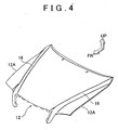
- (level difference portions) (relief portions) 16 are formed in the vicinity of vehicle-width-direction both ends of the hood outer panel 12 along a longitudinal direction of the vehicle body.
- Each of the relief portions 16 is formed from a portion the hood outer panel 12 which is in a front side of the vehicle body and which is in an inner side in the vehicle width direction to a portion of the hood outer panel 12 which is in a rear side of the vehicle body and which is in an outer side in the vehicle width direction.
- FIG. 3 several bone portions 18 are formed along the longitudinal direction of the vehicle at predetermined intervals in the vehicle width direction in a center region 14E of the hood inner panel 14.
- the center region 14E is a region other than a front edge portion 14A, a rear edge portion 14B, right and left vehicle-width-direction outer side line portions 14C and 14D of the hood inner panel 14, which are outer peripheral portions of the hood inner panel 14.
- a bone portion 20 is formed along the longitudinal direction of the vehicle at each vehicle-width-direction inner side portion which is positioned inside each of the vehicle-width-direction outer side line portions 14C and 14D.
- a notch 21 is formed between adjacent bone portions 18.
- Several adhesive agent application portions 22 are formed in an outer peripheral portion of the notch 21.
- vehicle-width-direction both ends 12A of the hood outer panel 12 are joined to vehicle-width-direction both ends 14F of the hood inner panel 14 by hemming process.
- Each of the bone portions 20 of the hood inner panel 14 protrudes toward a lower side of the vehicle body.
- a reinforcement 26 for a hood hinge is provided on an upper surface side of a bottom portion 20A of the bone portion 20.
- each of the bone portions 18 formed in the center region 14E of the hood inner panel 14 protrudes toward the lower side of the vehicle body.
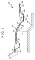
- a flange 30 that connects the bone portion 18 and the bone portion 20 is formed at a portion below the relief portion 16 of the hood outer panel 12.
- the flange 30 of the hood inner panel 14 extends so as to be curved along the relief portion 16 of the hood outer panel 12.
- the flange 30 of the hood inner panel 14 is joined to the relief portion 16 of the hood outer panel 12 through an adhesive agent 32 applied to the adhesive agent application portion 22.
- engine room components 36 such as an engine are provided below the flange 30 of the hood inner panel 14.
- vehicle-width-direction outer side line portion 14C of the hood inner panel 14 is not shown, it is the same as that of the vehicle-width-direction outer side line portion 14D of the hood inner panel 14 shown in FIG. 1 .
- the flange 30 that connects the bone portion 18 and the bone portion 20 is formed at the portion below the relief portion 16 of the hood outer panel 12.
- the hood 10 has a double structure composed of two panels, that is, the hood outer panel 12 and the hood inner panel 14. As a result, torsional rigidity of the hood 10 is improved. Also, as shown in FIG. 2 , when a hitting body K hits the relief portion 16 of the hood outer panel 12, the relief portion 16 of the hood outer panel 12 is unlikely to be inverted toward the lower side of the vehicle.
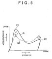
- a primary peak value P1 can be increased such that energy can be absorbed when a speed of the hitting body K is high, and a secondary peak value P2 can be decreased in the embodiment, as compared to an acceleration characteristic G1 shown by a dashed line in FIG. 5 in a comparative example in which the flange 30 is not formed. Accordingly, in the hood structure for a vehicle according to the embodiment, energy can be absorbed efficiently in a given space without providing a separate shock absorbing body.
- a separate shock absorbing body does not need to be provided between the hood outer panel 12 and the hood inner panel 14, it is possible to prevent an increase in the number of components, an increase in weight, and an increase in assembly cost. In addition, incomplete collapse of the shock absorbing body does not occur. As a result, even when there is only a limited space, energy can be absorbed efficiently using the limited space effectively.
- the thickness of the hood 10 is small. As a result, a distance L between the hood inner panel 14 and the engine room components 36 such as the engine below the hood is large, and a secondary hit on the engine room components 36 can be prevented.
- the relief portion 16 of the hood outer panel 12 is joined to the flange 30 of the hood inner panel 14 by the adhesive agent 32, tensile rigidity of the hood 10 is also improved.
- the flange 30 of the hood inner panel 14 extends so as to be curved along the relief portion 16 of the hood outer panel 12, as shown in FIG. 1 .
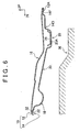
- the flange 30 of the hood inner panel 14 may be formed such that the cross section of the flange 30 is a straight line in the longitudinal direction of the vehicle body. In this case, the flange 30 is not inverted when the hitting body hits the relief portion 16 of the hood outer panel 12, and accordingly there is no excess stroke due to inversion of the flange 30, as shown in FIG. 7 .
- a bead 50 that is reinforcement means (a reinforcement portion) for connecting the bone portion 18 and the bone portion 20 for improving surface rigidity may be provided in the flange 30 of the hood inner panel 14.
- the bead 50 improves the surface rigidity of the flange 30, the flange 30 is more unlikely to be inverted, and stress is propagated to the bone portion 18 and the bone portion 20 more easily when the hitting body K hits the relief portion 16 of the hood outer panel 12.
- the primary peak value P1 of the acceleration can be further increased, and the rigidity of the hood 10 itself can be improved, as compared to the acceleration characteristic G shown by the solid line in FIG. 5 . Accordingly, even in the case where there is only a limited space, energy can be absorbed efficiently using the limited space effectively.
- each of the relief portions 16 is formed in the vicinity of each of vehicle-width both ends of the hood outer panel 12, from the portion which is in the front side of the vehicle body and which is in the inner side in the vehicle width direction to the portion which is in the rear side of the vehicle body and which is in the outer side in the vehicle width direction.
- the hood structure for a vehicle according to the invention can be applied.
- an opening portion may be formed in the flange 30 of the hood inner panel 14 in order to reduce weight.
Landscapes
- Engineering & Computer Science (AREA)
- Mechanical Engineering (AREA)
- Chemical & Material Sciences (AREA)
- Combustion & Propulsion (AREA)
- Transportation (AREA)
- Superstructure Of Vehicle (AREA)
Description
- The invention relates to a hood structure for a vehicle, such as an automobile.
-
JP 8-80873 A JP 8-80873 A - However, in the hood structure for a vehicle disclosed in the
Japanese Patent JP 8-80873 A - Other hood structures for vehicles, having a hood outer panel and a hood inner panel, a level difference portion formed on the hood outer panel along a longitudinal direction of a vehicle, bone portions on the hood inner panels along the longitudinal direction of the vehicle, and a flange formed on the hood inner panel to connect adjacent bone portions, are known from
JP 60-124575 A WO 02/476961 A1 EP 0992418 A2 .WO 02/476961 A1 claim 1 - It is an object of the invention to provide a hood structure for a vehicle which can improve energy absorbing efficiency without providing a separate shock absorbing body even in the case where there is only a limited space.
- This object is solved by a hood structure according to
claim 1. - According to the invention, a hood structure for a vehicle, includes a hood outer panel constituting a vehicle body outer side portion of a hood; a hood inner panel constituting a vehicle body inner side portion of the hood; a relief portion that is formed on the hood outer panel along a longitudinal direction of a vehicle; several bone portions that are formed in the hood inner panel along the longitudinal direction of the vehicle at predetermined intervals in a vehicle width direction, so as to protrude toward the lower side of the vehicle body; and a flange that is formed in the hood inner panel to connects adjacent bones among the several bones.
- According to the invention, the flange is formed at a portion of the hood inner panel below the relief portion of the hood outer panel and is joined to the relief portion.
- Thus, the several bone portions are formed in the hood inner panel along the longitudinal direction of the vehicle at the predetermined intervals in the vehicle width direction, and the flange connects the adjacent bones among the several bones at the portion below the relief portion. Therefore, the relief portion of the hood outer panel and the flange of the hood inner panel provide a double structure. As a result, torsional rigidity of the hood is improved. In addition, when a hitting body hits the vicinity of the relief portion of the hood outer panel, the hood outer panel is unlikely to be inverted toward a lower side of the vehicle. Accordingly, since a primary peak value of an acceleration applied to the hitting body can be increased without providing a separate shock absorbing body. Since the separate shock absorbing body does not need to be provided, the amount of incomplete collapse can be reduced by the amount of incomplete collapse of the separate shock absorbing body. Thus, energy can be absorbed efficiently even in the case where there is only a limited space.
- According to the invention, the flange may be formed such that a cross section of the flange in the longitudinal direction of the vehicle is a straight line.
- Thus, in addition to the above specified structure, the cross section of the flange in the longitudinal direction of the vehicle is a straight line. Therefore, the flange is not inverted when the hitting body hits the vicinity of the relief portion of the hood outer panel, and accordingly there is no excess stroke due to inversion of the flange. As a result, since tensile force is generated in the flange immediately after the hitting body hits the vicinity of the relief portion of the hood outer panel, the primary peak value can be generated early.
- According to the invention, reinforcement means for improving surface rigidity may be formed in the flange.
- Thus, in addition to the above specified structure, the reinforcement means improves the surface rigidity of the flange. As a result, the flange is unlikely to be inverted when the hitting body hits the vicinity of the relief portion of the hood outer panel, and stress is propagated to the bone portions easily. Accordingly, the primary peak value can be further increased, and the rigidity of the hood itself can be improved.
-
-
FIG 1 is an enlarged cross sectional view taken along line I-I inFIG. 3 ; -
FIG. 2 is a cross sectional view showing a deformed state of a hood structure for a vehicle according to an embodiment of the invention, which corresponds toFIG. 1 ; -
FIG. 3 is a plan view showing the hood structure for a vehicle according to the embodiment of the invention, which is seen from below a vehicle body; -
FIG. 4 is a perspective view showing a food outer panel of the hood structure for a vehicle according to the embodiment of the invention, which is seen obliquely from ahead of the vehicle body; -
FIG. 5 is a graph showing a relation between a stroke of a hitting body and an acceleration in the hood structure for a vehicle; -
FIG. 6 is a cross sectional view showing a hood structure for a vehicle according to another embodiment of the invention, which corresponds toFIG. 1 ; -
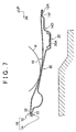
FIG. 7 is a cross sectional view showing a deformed state of the hood structure for a vehicle according to another embodiment of the invention, which corresponds toFIG. 6 ; and -
FIG. 8 is a perspective view showing a portion of the hood structure for a vehicle according to a yet another embodiment of the invention, which is seen obliquely from the outside of the vehicle body in a direction from a rear side toward a front side of the vehicle body. - Hereinafter, a hood structure for a vehicle according to an embodiment of the invention will be described with reference to
FIG. 1 to FIG. 5 . - In each of drawings, an arrow UP indicates an upward direction of a vehicle body, an arrow FR indicates a forward direction of the vehicle body, and an arrow IN indicates an inward direction of a vehicle width.
- As shown in
FIG. 3 , ahood 10 according to the embodiment includes a hoodouter panel 12 and a hoodinner panel 14. The hoodouter panel 12 constitutes a vehicle body outer side surface of thehood 10. The hoodinner panel 14 is provided on the inner side (i.e., on the rear surface side) of the hoodouter panel 12, and constitutes a vehicle body inner side portion of thehood 10. - As shown in
FIG 4 , (level difference portions) (relief portions) 16 are formed in the vicinity of vehicle-width-direction both ends of the hoodouter panel 12 along a longitudinal direction of the vehicle body. Each of therelief portions 16 is formed from a portion the hoodouter panel 12 which is in a front side of the vehicle body and which is in an inner side in the vehicle width direction to a portion of the hoodouter panel 12 which is in a rear side of the vehicle body and which is in an outer side in the vehicle width direction. - As shown in
FIG. 3 ,several bone portions 18 are formed along the longitudinal direction of the vehicle at predetermined intervals in the vehicle width direction in acenter region 14E of the hoodinner panel 14. Thecenter region 14E is a region other than afront edge portion 14A, arear edge portion 14B, right and left vehicle-width-direction outerside line portions inner panel 14, which are outer peripheral portions of the hoodinner panel 14. Abone portion 20 is formed along the longitudinal direction of the vehicle at each vehicle-width-direction inner side portion which is positioned inside each of the vehicle-width-direction outerside line portions - Also, a
notch 21 is formed betweenadjacent bone portions 18. Several adhesiveagent application portions 22 are formed in an outer peripheral portion of thenotch 21. - As shown in
FIG. 1 , vehicle-width-direction bothends 12A of the hoodouter panel 12 are joined to vehicle-width-direction bothends 14F of the hoodinner panel 14 by hemming process. - Each of the
bone portions 20 of the hoodinner panel 14 protrudes toward a lower side of the vehicle body. Areinforcement 26 for a hood hinge is provided on an upper surface side of abottom portion 20A of thebone portion 20. Meanwhile, each of thebone portions 18 formed in thecenter region 14E of the hoodinner panel 14 protrudes toward the lower side of the vehicle body. Aflange 30 that connects thebone portion 18 and thebone portion 20 is formed at a portion below therelief portion 16 of the hoodouter panel 12. - The
flange 30 of the hoodinner panel 14 extends so as to be curved along therelief portion 16 of the hoodouter panel 12. Theflange 30 of the hoodinner panel 14 is joined to therelief portion 16 of the hoodouter panel 12 through anadhesive agent 32 applied to the adhesiveagent application portion 22. Also,engine room components 36 such as an engine are provided below theflange 30 of the hoodinner panel 14. - Although the structure of the vehicle-width-direction outer
side line portion 14C of the hoodinner panel 14 is not shown, it is the same as that of the vehicle-width-direction outerside line portion 14D of the hoodinner panel 14 shown inFIG. 1 . - Next, effects of the embodiment will be described.
- In the embodiment, the
flange 30 that connects thebone portion 18 and thebone portion 20 is formed at the portion below therelief portion 16 of the hoodouter panel 12. Thehood 10 has a double structure composed of two panels, that is, the hoodouter panel 12 and the hoodinner panel 14. As a result, torsional rigidity of thehood 10 is improved. Also, as shown inFIG. 2 , when a hitting body K hits therelief portion 16 of the hoodouter panel 12, therelief portion 16 of the hoodouter panel 12 is unlikely to be inverted toward the lower side of the vehicle. - Therefore, as shown by a solid line in
FIG. 5 , in a change in an acceleration G applied to the hitting body K (acceleration characteristic G) with respect to a stroke S of the hitting body K, a primary peak value P1 can be increased such that energy can be absorbed when a speed of the hitting body K is high, and a secondary peak value P2 can be decreased in the embodiment, as compared to an acceleration characteristic G1 shown by a dashed line inFIG. 5 in a comparative example in which theflange 30 is not formed. Accordingly, in the hood structure for a vehicle according to the embodiment, energy can be absorbed efficiently in a given space without providing a separate shock absorbing body. - Since a separate shock absorbing body does not need to be provided between the hood
outer panel 12 and the hoodinner panel 14, it is possible to prevent an increase in the number of components, an increase in weight, and an increase in assembly cost. In addition, incomplete collapse of the shock absorbing body does not occur. As a result, even when there is only a limited space, energy can be absorbed efficiently using the limited space effectively. - Also, since a separate shock absorbing body does not need to be provided between the hood
outer panel 12 and the hoodinner panel 14, the thickness of thehood 10 is small. As a result, a distance L between the hoodinner panel 14 and theengine room components 36 such as the engine below the hood is large, and a secondary hit on theengine room components 36 can be prevented. - Also, in the embodiment, since the
relief portion 16 of the hoodouter panel 12 is joined to theflange 30 of the hoodinner panel 14 by theadhesive agent 32, tensile rigidity of thehood 10 is also improved. - The specific embodiment of the invention has been described in detail so far. However, the invention is not limited to the embodiment. It is apparent to persons skilled in the art that the invention can be realized in various embodiments. For example, the
flange 30 of the hoodinner panel 14 extends so as to be curved along therelief portion 16 of the hoodouter panel 12, as shown inFIG. 1 . Instead, as shown inFIG. 6 , theflange 30 of the hoodinner panel 14 may be formed such that the cross section of theflange 30 is a straight line in the longitudinal direction of the vehicle body. In this case, theflange 30 is not inverted when the hitting body hits therelief portion 16 of the hoodouter panel 12, and accordingly there is no excess stroke due to inversion of theflange 30, as shown inFIG. 7 . As a result, tensile force is generated in theflange 30 immediately after the hitting body K hits therelief portion 16 of the hoodouter panel 12. Therefore, the primary peak value P1 of the acceleration can be generated early as compared to the acceleration characteristic G shown by the solid line inFIG. 5 . Accordingly, even in the case where there is only a limited space, energy can be absorbed efficiently using the limited space effectively. - Also, as shown in
FIG. 8 , abead 50 that is reinforcement means (a reinforcement portion) for connecting thebone portion 18 and thebone portion 20 for improving surface rigidity may be provided in theflange 30 of the hoodinner panel 14. In this case, since thebead 50 improves the surface rigidity of theflange 30, theflange 30 is more unlikely to be inverted, and stress is propagated to thebone portion 18 and thebone portion 20 more easily when the hitting body K hits therelief portion 16 of the hoodouter panel 12. As a result, the primary peak value P1 of the acceleration can be further increased, and the rigidity of thehood 10 itself can be improved, as compared to the acceleration characteristic G shown by the solid line inFIG. 5 . Accordingly, even in the case where there is only a limited space, energy can be absorbed efficiently using the limited space effectively. - In the aforementioned embodiment, each of the
relief portions 16 is formed in the vicinity of each of vehicle-width both ends of the hoodouter panel 12, from the portion which is in the front side of the vehicle body and which is in the inner side in the vehicle width direction to the portion which is in the rear side of the vehicle body and which is in the outer side in the vehicle width direction. However, in the case where each of therelief portions 16 is formed on the hoodouter panel 12 at another portion, the hood structure for a vehicle according to the invention can be applied. - Also, an opening portion may be formed in the
flange 30 of the hoodinner panel 14 in order to reduce weight.
Claims (9)
- A hood structure for a vehicle, including a hood outer panel (12) constituting a vehicle body outer side portion of a hood (10), and a hood inner panel (14) constituting a vehicle body inner side portion of the hood (10), comprising:a relief portion (16) that is formed on the hood outer panel (12) along a longitudinal direction of a vehicle;several bone portions (18, 20) that are formed in the hood inner panel (14) along the longitudinal direction of the vehicle at predetermined intervals in a vehicle width direction, so as to protrude toward the lower side of the vehicle body; anda flange (30) that is formed in the hood inner panel (14) to connects adjacent two bone portions (18, 20) from among the several bone portions (18, 20)characterized in that
the flange (30) is formed at a portion of the hood inner panel (14), which is below the relief portion (16) of the hood outer panel (12). - The hood structure for a vehicle according to claim 1, wherein the flange (30) is formed such that a cross section of the flange in the longitudinal direction of the vehicle is a straight line.
- The hood structure for a vehicle according to claim 1 or 2, wherein reinforcement means (50) for improving surface rigidity is formed in the flange (30).
- The hood structure for a vehicle according to claim 3, wherein the reinforcement means (50) is a bead.
- The hood structure for a vehicle according to claim 1, wherein the relief portion (16) is formed from a portion of the hood outer panel (12) which is in a front side of the vehicle body and which is in an inner side in the vehicle width direction to a portion of the hood outer panel (12) which is in a rear side of the vehicle body and which is in an outer side in the vehicle width direction.
- The hood structure for a vehicle according to claim 1, wherein a notch (21) is formed between adjacent two bone portions (18) other than the adjacent two bone portions (18, 20) which are connected by the flange (30), from among the several bone portions (18, 20).
- The hood structure for a vehicle according to claim 1, wherein the flange (30) extends so as to be curved along the portion (16).
- The hood structure for a vehicle according claim 1, wherein the adjacent two bone portions (18, 20) which are connected by the flange (30) extend each laterally of the vehicle-width-direction both sides of the relief portion (16).
- The hood structure for a vehicle according to claim 1, wherein the flange (30) is disposed at a predetermined interval in the vehicle-height-direction with respect to the relief portion (16) and is joined to the relief portion (16) through an adhesive agent (32).
Applications Claiming Priority (2)
| Application Number | Priority Date | Filing Date | Title |
|---|---|---|---|
| JP2003365731 | 2003-10-27 | ||
| JP2003365731A JP4059187B2 (en) | 2003-10-27 | 2003-10-27 | Vehicle hood structure |
Publications (3)
| Publication Number | Publication Date |
|---|---|
| EP1527984A2 EP1527984A2 (en) | 2005-05-04 |
| EP1527984A3 EP1527984A3 (en) | 2005-06-15 |
| EP1527984B1 true EP1527984B1 (en) | 2008-02-13 |
Family
ID=34420095
Family Applications (1)
| Application Number | Title | Priority Date | Filing Date |
|---|---|---|---|
| EP04024208A Expired - Lifetime EP1527984B1 (en) | 2003-10-27 | 2004-10-11 | Hood structure for vehicle |
Country Status (7)
| Country | Link |
|---|---|
| US (1) | US7140673B2 (en) |
| EP (1) | EP1527984B1 (en) |
| JP (1) | JP4059187B2 (en) |
| KR (1) | KR100676948B1 (en) |
| CN (2) | CN1315684C (en) |
| AU (1) | AU2004222857B2 (en) |
| DE (1) | DE602004011722T2 (en) |
Families Citing this family (37)
| Publication number | Priority date | Publication date | Assignee | Title |
|---|---|---|---|---|
| JP2005075176A (en) * | 2003-09-01 | 2005-03-24 | Toyota Motor Corp | Vehicle hood structure |
| JP4059187B2 (en) * | 2003-10-27 | 2008-03-12 | トヨタ自動車株式会社 | Vehicle hood structure |
| JP4470607B2 (en) * | 2004-06-21 | 2010-06-02 | マツダ株式会社 | Vehicle hood structure |
| US20100244482A1 (en) * | 2005-09-12 | 2010-09-30 | Montagna John C | Tonneau Cover |
| USD574763S1 (en) | 2005-09-13 | 2008-08-12 | Durakon Industries, Inc. | Tonneau cover |
| FR2891236A1 (en) * | 2005-09-29 | 2007-03-30 | Plastic Omnium Cie | AUTOMOTIVE VEHICLE COVER FOR CLOSING A MOTOR COMPARTMENT CONTAINING RIGID PARTS |
| JP4961764B2 (en) * | 2006-02-10 | 2012-06-27 | マツダ株式会社 | Automotive engine hood structure |
| JP4719039B2 (en) * | 2006-03-15 | 2011-07-06 | 株式会社神戸製鋼所 | Automotive hood |
| JP4664874B2 (en) * | 2006-07-07 | 2011-04-06 | 株式会社神戸製鋼所 | Automotive hood |
| FR2907078B1 (en) | 2006-10-17 | 2009-01-16 | Plastic Omnium Cie | HOOD FOR A MOTOR VEHICLE WITH HOLLOW BODIES |
| JP4200506B2 (en) * | 2006-10-27 | 2008-12-24 | いすゞ自動車株式会社 | In-vehicle component mounting structure |
| FR2911842B1 (en) * | 2007-01-31 | 2009-08-21 | Peugeot Citroen Automobiles Sa | FRONT HOOD STRUCTURE OF VEHICLE |
| JP2010520121A (en) * | 2007-03-07 | 2010-06-10 | アルコア インコーポレイテッド | Pedestrian safe car hood with reinforcing foam |
| US7735908B2 (en) * | 2007-07-24 | 2010-06-15 | Gm Global Technology Operations, Inc. | Vehicle hood with sandwich inner structure |
| US20090026807A1 (en) * | 2007-07-24 | 2009-01-29 | Gm Global Technology Operations, Inc. | Energy-Absorbing Vehicle Hood Assembly with Cushion Inner Structure |
| US7635157B2 (en) * | 2007-09-11 | 2009-12-22 | GM Global Technology Operation, INC | Vehicle hood assembly with rippled cushion support |
| DE102007053171B4 (en) * | 2007-11-08 | 2024-10-02 | Dr. Ing. H.C. F. Porsche Aktiengesellschaft | hood for a motor vehicle |
| FR2937609B1 (en) * | 2008-10-27 | 2012-12-21 | Plastic Omnium Cie | VEHICLE HOOD LINING |
| DE202009017786U1 (en) * | 2009-09-17 | 2010-06-17 | GM Global Technology Operations, Inc., Detroit | Body for a motor vehicle |
| EP2542461A4 (en) * | 2010-03-05 | 2013-09-04 | Shape Corp | PEDESTRIAN ENERGY ABSORPTION COVER |
| FR2964923A1 (en) * | 2010-09-16 | 2012-03-23 | Peugeot Citroen Automobiles Sa | VEHICLE DESIGNED TO MINIMIZE A PIECE SHOCK |
| JP2012106653A (en) * | 2010-11-18 | 2012-06-07 | Honda Motor Co Ltd | Front hood structure for vehicle |
| JP5589794B2 (en) * | 2010-11-19 | 2014-09-17 | スズキ株式会社 | Vehicle front hood |
| JP5711942B2 (en) * | 2010-11-19 | 2015-05-07 | 日本プラスト株式会社 | Cowl top cover |
| US8424629B2 (en) | 2011-03-09 | 2013-04-23 | Shape Corp. | Vehicle energy absorber for pedestrian's upper leg |
| US9248866B2 (en) | 2014-06-13 | 2016-02-02 | Toyota Motor Engineering & Manufacturing North America, Inc. | Hood assembly |
| US9381879B2 (en) | 2014-11-12 | 2016-07-05 | GM Global Technology Operations LLC | Local energy absorber |
| US9593517B2 (en) | 2014-12-31 | 2017-03-14 | Toyota Motor Engineering & Manufacturing North America, Inc. | Vehicles having load-transferring hood hinge members |
| US9499209B1 (en) * | 2015-07-15 | 2016-11-22 | Ford Global Technologies, Llc | Solar-activated structure for revealing a hidden indicia within a body panel of a vehicle |
| US10092055B2 (en) | 2016-01-06 | 2018-10-09 | GM Global Technology Operations LLC | Local energy absorber |
| US10246044B2 (en) | 2016-02-12 | 2019-04-02 | Ford Global Technologies, Llc | Vehicle hood assembly with deployable pedestrian protection |
| JP6718726B2 (en) * | 2016-03-31 | 2020-07-08 | 株式会社神戸製鋼所 | Vehicle hood |
| US10144457B2 (en) * | 2016-03-31 | 2018-12-04 | Kobe Steel, Ltd. | Vehicle hood |
| CN109501869A (en) * | 2018-10-23 | 2019-03-22 | 中国第汽车股份有限公司 | A kind of passenger car aluminum alloy engine hood |
| CN117460661A (en) * | 2021-06-04 | 2024-01-26 | 日本制铁株式会社 | Automobile cover and manufacturing method thereof |
| FR3128437A1 (en) * | 2021-10-25 | 2023-04-28 | Psa Automobiles Sa | Motor vehicle hood comprising an arch-shaped liner |
| CN118665610A (en) * | 2023-03-20 | 2024-09-20 | 本田技研工业株式会社 | Automotive panel structure |
Family Cites Families (30)
| Publication number | Priority date | Publication date | Assignee | Title |
|---|---|---|---|---|
| JPS60124575A (en) * | 1983-12-08 | 1985-07-03 | Nissan Motor Co Ltd | Engine hood structure for car |
| US5124191A (en) * | 1991-03-11 | 1992-06-23 | Aluminum Company Of America | Structural panel |
| JPH05155355A (en) * | 1991-12-03 | 1993-06-22 | Toyota Motor Corp | Engine hood structure |
| US5706908A (en) * | 1994-04-18 | 1998-01-13 | Nissan Motor Co., Ltd. | Front upper structure of automotive vehicle |
| JP3329086B2 (en) | 1994-09-14 | 2002-09-30 | 日産自動車株式会社 | Car hood |
| JP3871744B2 (en) * | 1996-10-25 | 2007-01-24 | 本田技研工業株式会社 | Synthetic resin panels for automobiles |
| JP3531789B2 (en) * | 1998-05-13 | 2004-05-31 | 本田技研工業株式会社 | Car hood |
| DE19846192A1 (en) * | 1998-10-07 | 2000-04-13 | Volkswagen Ag | Body hood, in particular engine compartment hood of a motor vehicle |
| DE59901135D1 (en) * | 1999-10-21 | 2002-05-08 | Ford Global Tech Inc | Bonnet for motor vehicles to protect pedestrians |
| JP2001122049A (en) * | 1999-10-26 | 2001-05-08 | Kobe Steel Ltd | PANEL STRUCTURE BODY FOR TRANSPORT AIRPLANE EXCELLENT IN SOUND INSULATING PROPERTY IN FREQUENCY BAND OF 1 kHz OR LESS |
| DE60126673T2 (en) * | 2000-12-13 | 2007-10-31 | Kabushiki Kaisha Kobe Seiko Sho, Kobe | FAIRING CONSTRUCTION FOR HOOD OF A PASSENGER CAR CONSTRUCTION |
| JP3823834B2 (en) * | 2002-01-23 | 2006-09-20 | 日産自動車株式会社 | Internal structure of vehicle opening / closing body |
| ITMI20021042A1 (en) * | 2002-05-16 | 2003-11-17 | Adlev Srl | BONNET STRUCTURE FOR CARS WITH IMPROVED SAFETY FEATURES |
| JP2004122973A (en) * | 2002-10-03 | 2004-04-22 | Fuji Heavy Ind Ltd | Vehicle front hood |
| JP4192602B2 (en) * | 2003-01-14 | 2008-12-10 | トヨタ自動車株式会社 | Vehicle hood structure |
| JP2005053265A (en) * | 2003-08-06 | 2005-03-03 | Toyota Motor Corp | Vehicle hood structure |
| JP4289072B2 (en) * | 2003-08-11 | 2009-07-01 | スズキ株式会社 | Car hood structure |
| JP4053482B2 (en) * | 2003-09-01 | 2008-02-27 | トヨタ自動車株式会社 | Vehicle hood structure |
| JP2005075176A (en) * | 2003-09-01 | 2005-03-24 | Toyota Motor Corp | Vehicle hood structure |
| JP2005075163A (en) * | 2003-09-01 | 2005-03-24 | Toyota Motor Corp | Vehicle hood structure |
| JP4422454B2 (en) * | 2003-09-22 | 2010-02-24 | トヨタ自動車株式会社 | Vehicle hood structure |
| JP4053485B2 (en) * | 2003-09-25 | 2008-02-27 | トヨタ自動車株式会社 | Vehicle hood structure |
| JP4076487B2 (en) * | 2003-09-25 | 2008-04-16 | トヨタ自動車株式会社 | Vehicle hood structure |
| JP2005104274A (en) * | 2003-09-30 | 2005-04-21 | Toyota Motor Corp | Vehicle hood structure |
| JP4059187B2 (en) * | 2003-10-27 | 2008-03-12 | トヨタ自動車株式会社 | Vehicle hood structure |
| JP2005145224A (en) * | 2003-11-14 | 2005-06-09 | Toyota Motor Corp | Vehicle hood structure |
| JP4200907B2 (en) * | 2004-01-27 | 2008-12-24 | トヨタ自動車株式会社 | Vehicle hood structure |
| JP2005239092A (en) * | 2004-02-27 | 2005-09-08 | Kanto Auto Works Ltd | Hood structure for automobile |
| JP4214929B2 (en) * | 2004-03-08 | 2009-01-28 | トヨタ自動車株式会社 | Vehicle hood structure |
| JP4470607B2 (en) * | 2004-06-21 | 2010-06-02 | マツダ株式会社 | Vehicle hood structure |
-
2003
- 2003-10-27 JP JP2003365731A patent/JP4059187B2/en not_active Expired - Fee Related
-
2004
- 2004-10-11 DE DE602004011722T patent/DE602004011722T2/en not_active Expired - Lifetime
- 2004-10-11 EP EP04024208A patent/EP1527984B1/en not_active Expired - Lifetime
- 2004-10-20 US US10/968,079 patent/US7140673B2/en not_active Expired - Lifetime
- 2004-10-26 CN CNB2004100870947A patent/CN1315684C/en not_active Expired - Lifetime
- 2004-10-26 KR KR1020040085594A patent/KR100676948B1/en not_active Expired - Fee Related
- 2004-10-26 AU AU2004222857A patent/AU2004222857B2/en not_active Ceased
- 2004-10-27 CN CNU2004201176667U patent/CN2744580Y/en not_active Expired - Lifetime
Also Published As
| Publication number | Publication date |
|---|---|
| JP4059187B2 (en) | 2008-03-12 |
| KR20050040734A (en) | 2005-05-03 |
| DE602004011722T2 (en) | 2009-01-29 |
| CN2744580Y (en) | 2005-12-07 |
| KR100676948B1 (en) | 2007-01-31 |
| EP1527984A3 (en) | 2005-06-15 |
| AU2004222857A1 (en) | 2005-05-12 |
| CN1611407A (en) | 2005-05-04 |
| CN1315684C (en) | 2007-05-16 |
| DE602004011722D1 (en) | 2008-03-27 |
| AU2004222857B2 (en) | 2007-02-22 |
| US7140673B2 (en) | 2006-11-28 |
| EP1527984A2 (en) | 2005-05-04 |
| JP2005125989A (en) | 2005-05-19 |
| US20050088016A1 (en) | 2005-04-28 |
Similar Documents
| Publication | Publication Date | Title |
|---|---|---|
| US7140673B2 (en) | Hood structure for vehicle | |
| KR100644416B1 (en) | Vehicle hood structure | |
| EP2112981B1 (en) | Vehicle front side member | |
| JP3828329B2 (en) | Auto body structure | |
| US20160083019A1 (en) | Bonnet structure of automotive vehicle | |
| US6938950B2 (en) | Vehicle body structure | |
| JP2003226266A (en) | Body front structure | |
| WO2010097690A1 (en) | Vehicle front structure | |
| EP4159546B1 (en) | Front structure of vehicle | |
| US20190232904A1 (en) | Skeleton structure of vehicle front part | |
| JP2005145224A (en) | Vehicle hood structure | |
| JPH11115818A (en) | Front side member base structure | |
| JP3617481B2 (en) | Auto body front structure | |
| JP3622715B2 (en) | Body front structure | |
| JP4053485B2 (en) | Vehicle hood structure | |
| CN114162222B (en) | Front structure of vehicle body | |
| JP3632654B2 (en) | Body front structure | |
| CN108349547B (en) | The front body structure of the car | |
| KR20220120258A (en) | Cowl reinforcement structure of vehicle | |
| CN113173139A (en) | Vehicle body structure of vehicle | |
| EP2428432B1 (en) | Front side vehicle body structure | |
| JP4214851B2 (en) | Vehicle hood structure | |
| JP2025043067A (en) | Vehicle Structure | |
| JP2005161892A (en) | Body front structure | |
| KR20010060904A (en) | reinforcement structure for front body portion of automobile |
Legal Events
| Date | Code | Title | Description |
|---|---|---|---|
| PUAI | Public reference made under article 153(3) epc to a published international application that has entered the european phase |
Free format text: ORIGINAL CODE: 0009012 |
|
| PUAL | Search report despatched |
Free format text: ORIGINAL CODE: 0009013 |
|
| 17P | Request for examination filed |
Effective date: 20041108 |
|
| AK | Designated contracting states |
Kind code of ref document: A2 Designated state(s): AT BE BG CH CY CZ DE DK EE ES FI FR GB GR HU IE IT LI LU MC NL PL PT RO SE SI SK TR |
|
| AX | Request for extension of the european patent |
Extension state: AL HR LT LV MK |
|
| AK | Designated contracting states |
Kind code of ref document: A3 Designated state(s): AT BE BG CH CY CZ DE DK EE ES FI FR GB GR HU IE IT LI LU MC NL PL PT RO SE SI SK TR |
|
| AX | Request for extension of the european patent |
Extension state: AL HR LT LV MK |
|
| AKX | Designation fees paid |
Designated state(s): DE FR GB IT |
|
| GRAP | Despatch of communication of intention to grant a patent |
Free format text: ORIGINAL CODE: EPIDOSNIGR1 |
|
| GRAS | Grant fee paid |
Free format text: ORIGINAL CODE: EPIDOSNIGR3 |
|
| GRAA | (expected) grant |
Free format text: ORIGINAL CODE: 0009210 |
|
| AK | Designated contracting states |
Kind code of ref document: B1 Designated state(s): DE FR GB IT |
|
| REG | Reference to a national code |
Ref country code: GB Ref legal event code: FG4D |
|
| RIN1 | Information on inventor provided before grant (corrected) |
Inventor name: ITO, KATSUYOSHI Inventor name: MORIKAWA, MASAAKI Inventor name: IKEDA, KOKI |
|
| REF | Corresponds to: |
Ref document number: 602004011722 Country of ref document: DE Date of ref document: 20080327 Kind code of ref document: P |
|
| REG | Reference to a national code |
Ref country code: DE Ref legal event code: R096 Ref document number: 602004011722 Country of ref document: DE Effective date: 20080327 |
|
| ET | Fr: translation filed | ||
| PLBE | No opposition filed within time limit |
Free format text: ORIGINAL CODE: 0009261 |
|
| STAA | Information on the status of an ep patent application or granted ep patent |
Free format text: STATUS: NO OPPOSITION FILED WITHIN TIME LIMIT |
|
| 26N | No opposition filed |
Effective date: 20081114 |
|
| REG | Reference to a national code |
Ref country code: DE Ref legal event code: R097 Ref document number: 602004011722 Country of ref document: DE Effective date: 20081114 |
|
| REG | Reference to a national code |
Ref country code: GB Ref legal event code: 746 Effective date: 20130717 |
|
| REG | Reference to a national code |
Ref country code: DE Ref legal event code: R084 Ref document number: 602004011722 Country of ref document: DE Effective date: 20130717 |
|
| REG | Reference to a national code |
Ref country code: FR Ref legal event code: PLFP Year of fee payment: 13 |
|
| REG | Reference to a national code |
Ref country code: FR Ref legal event code: PLFP Year of fee payment: 14 |
|
| REG | Reference to a national code |
Ref country code: FR Ref legal event code: PLFP Year of fee payment: 15 |
|
| PGFP | Annual fee paid to national office [announced via postgrant information from national office to epo] |
Ref country code: IT Payment date: 20210910 Year of fee payment: 18 Ref country code: FR Payment date: 20210913 Year of fee payment: 18 |
|
| PGFP | Annual fee paid to national office [announced via postgrant information from national office to epo] |
Ref country code: GB Payment date: 20210901 Year of fee payment: 18 |
|
| P01 | Opt-out of the competence of the unified patent court (upc) registered |
Effective date: 20230517 |
|
| GBPC | Gb: european patent ceased through non-payment of renewal fee |
Effective date: 20221011 |
|
| PG25 | Lapsed in a contracting state [announced via postgrant information from national office to epo] |
Ref country code: FR Free format text: LAPSE BECAUSE OF NON-PAYMENT OF DUE FEES Effective date: 20221031 |
|
| PG25 | Lapsed in a contracting state [announced via postgrant information from national office to epo] |
Ref country code: IT Free format text: LAPSE BECAUSE OF NON-PAYMENT OF DUE FEES Effective date: 20221011 Ref country code: GB Free format text: LAPSE BECAUSE OF NON-PAYMENT OF DUE FEES Effective date: 20221011 |
|
| PGFP | Annual fee paid to national office [announced via postgrant information from national office to epo] |
Ref country code: DE Payment date: 20230830 Year of fee payment: 20 |
|
| REG | Reference to a national code |
Ref country code: DE Ref legal event code: R071 Ref document number: 602004011722 Country of ref document: DE |