EP1527960A2 - Dispositif de protection des occupants - Google Patents
Dispositif de protection des occupants Download PDFInfo
- Publication number
- EP1527960A2 EP1527960A2 EP04256089A EP04256089A EP1527960A2 EP 1527960 A2 EP1527960 A2 EP 1527960A2 EP 04256089 A EP04256089 A EP 04256089A EP 04256089 A EP04256089 A EP 04256089A EP 1527960 A2 EP1527960 A2 EP 1527960A2
- Authority
- EP
- European Patent Office
- Prior art keywords
- threshold value
- ecu
- webbing
- brake pedal
- accelerator pedal
- Prior art date
- Legal status (The legal status is an assumption and is not a legal conclusion. Google has not performed a legal analysis and makes no representation as to the accuracy of the status listed.)
- Granted
Links
Images


Classifications
-
- B—PERFORMING OPERATIONS; TRANSPORTING
- B60—VEHICLES IN GENERAL
- B60R—VEHICLES, VEHICLE FITTINGS, OR VEHICLE PARTS, NOT OTHERWISE PROVIDED FOR
- B60R21/00—Arrangements or fittings on vehicles for protecting or preventing injuries to occupants or pedestrians in case of accidents or other traffic risks
- B60R21/01—Electrical circuits for triggering passive safety arrangements, e.g. airbags, safety belt tighteners, in case of vehicle accidents or impending vehicle accidents
- B60R21/013—Electrical circuits for triggering passive safety arrangements, e.g. airbags, safety belt tighteners, in case of vehicle accidents or impending vehicle accidents including means for detecting collisions, impending collisions or roll-over
-
- B—PERFORMING OPERATIONS; TRANSPORTING
- B60—VEHICLES IN GENERAL
- B60R—VEHICLES, VEHICLE FITTINGS, OR VEHICLE PARTS, NOT OTHERWISE PROVIDED FOR
- B60R21/00—Arrangements or fittings on vehicles for protecting or preventing injuries to occupants or pedestrians in case of accidents or other traffic risks
- B60R21/01—Electrical circuits for triggering passive safety arrangements, e.g. airbags, safety belt tighteners, in case of vehicle accidents or impending vehicle accidents
- B60R21/015—Electrical circuits for triggering passive safety arrangements, e.g. airbags, safety belt tighteners, in case of vehicle accidents or impending vehicle accidents including means for detecting the presence or position of passengers, passenger seats or child seats, and the related safety parameters therefor, e.g. speed or timing of airbag inflation in relation to occupant position or seat belt use
- B60R21/01512—Passenger detection systems
- B60R21/01544—Passenger detection systems detecting seat belt parameters, e.g. length, tension or height-adjustment
- B60R21/01546—Passenger detection systems detecting seat belt parameters, e.g. length, tension or height-adjustment using belt buckle sensors
-
- B—PERFORMING OPERATIONS; TRANSPORTING
- B60—VEHICLES IN GENERAL
- B60R—VEHICLES, VEHICLE FITTINGS, OR VEHICLE PARTS, NOT OTHERWISE PROVIDED FOR
- B60R21/00—Arrangements or fittings on vehicles for protecting or preventing injuries to occupants or pedestrians in case of accidents or other traffic risks
- B60R21/02—Occupant safety arrangements or fittings, e.g. crash pads
- B60R21/16—Inflatable occupant restraints or confinements designed to inflate upon impact or impending impact, e.g. air bags
- B60R21/33—Arrangements for non-electric triggering of inflation
-
- B—PERFORMING OPERATIONS; TRANSPORTING
- B60—VEHICLES IN GENERAL
- B60R—VEHICLES, VEHICLE FITTINGS, OR VEHICLE PARTS, NOT OTHERWISE PROVIDED FOR
- B60R21/00—Arrangements or fittings on vehicles for protecting or preventing injuries to occupants or pedestrians in case of accidents or other traffic risks
- B60R21/01—Electrical circuits for triggering passive safety arrangements, e.g. airbags, safety belt tighteners, in case of vehicle accidents or impending vehicle accidents
- B60R2021/01204—Actuation parameters of safety arrangents
- B60R2021/01252—Devices other than bags
- B60R2021/01265—Seat belts
- B60R2021/01272—Belt tensioners
-
- B—PERFORMING OPERATIONS; TRANSPORTING
- B60—VEHICLES IN GENERAL
- B60R—VEHICLES, VEHICLE FITTINGS, OR VEHICLE PARTS, NOT OTHERWISE PROVIDED FOR
- B60R21/00—Arrangements or fittings on vehicles for protecting or preventing injuries to occupants or pedestrians in case of accidents or other traffic risks
- B60R21/01—Electrical circuits for triggering passive safety arrangements, e.g. airbags, safety belt tighteners, in case of vehicle accidents or impending vehicle accidents
- B60R21/013—Electrical circuits for triggering passive safety arrangements, e.g. airbags, safety belt tighteners, in case of vehicle accidents or impending vehicle accidents including means for detecting collisions, impending collisions or roll-over
- B60R2021/01311—Electrical circuits for triggering passive safety arrangements, e.g. airbags, safety belt tighteners, in case of vehicle accidents or impending vehicle accidents including means for detecting collisions, impending collisions or roll-over monitoring the braking system, e.g. ABS
Definitions
- the present invention relates to a passenger protection device configured to retract the webbing of a seatbelt using an electric motor. More particularly, the present invention relates to a technology for controlling the retraction of the webbing in accordance with the situation.
- Japanese Laid-Open Patent Publication No. 2001-253317 discloses a passenger restraining device to determine if an emergency situation exists in which there is the possibility that the vehicle in which the passenger restraining device is installed will come abnormally close to a preceding vehicle or an obstacle and, if such an emergency situation exists, to retract the seatbelt using an electric motor.
- the passenger restraining device uses information regarding the operation of the brakes by the driver while driving (e.g., depression of the brake pedal, brake fluid pressure) in order to determine if such an emergency situation exists.
- Japanese Laid-Open Patent Publication No. 2000-190815 discloses a technology provided with a belt control device configured to control the belt tension of a seatbelt in accordance with the driving conditions of the vehicle and belt wearer status detecting means to detect the posture of a passenger wearing a seatbelt, the belt tension control being executed based on information indicating the detected posture of the belt wearer.
- the device controls the seatbelt tension in such a manner that the seatbelt tension increases as a quantity expressing a vehicle driving operation (e.g., brake pedal depression speed, brake pedal depression force, steering operating angle, etc.) increases, said quantity being detected and provided as vehicle state detection information.
- a vehicle driving operation e.g., brake pedal depression speed, brake pedal depression force, steering operating angle, etc.
- Japanese Laid-Open Patent Publication No. 2001-253317 and Japanese Laid-Open Patent Publication No. 2000-190815 are configured such that the motor retracts the slack in the seatbelt and restrains the passenger in the same manner whenever an emergency brake operation by the driver is detected. Thus, the surrounding circumstances are not taken into consideration.
- the degree of passenger protection may improve but the device will be lacking from the perspective of driver comfort because it will become an annoyance.
- the present invention was conceived to address these issues and its object is to provide a passenger protection device that takes the driving conditions into consideration and ensures a high restraining performance without debasing the comfort of the passenger.
- An aspect of the present invention provides a passenger protection device that includes, a brake pedal sensor configured to detect the amount by which a brake pedal of a vehicle is operated, a webbing, one end of the webbing fixed to the vehicle, configured to restrain a passenger seated on a seat of the vehicle, a retractor connected to the other end of the webbing, the retractor configured to retract the webbing and inhibit of the webbing extraction, and an ECU electrically coupled to the brake pedal sensor, the ECU configured to detect that the brake pedal operation amount detected by the pedal sensor exceeds a first threshold value, the ECU configured to revise the threshold value based on safety related information of the vehicle to control the inhibition of the webbing extraction of the retractor.
- FIG. 1 is a diagrammatic view for explaining a first embodiment of a passenger protection device in accordance with the present invention.
- the passenger protection device 100 is provided with a webbing 102 that serves to restrain a passenger P sitting in a seat S, and a retractor 103 configured to store the webbing 102 using an electric motor 104 configured to provided power to wind up one end of the webbing 102.
- the other end of the seatbelt is fastened to the vehicle body through an anchor arranged on the door side of the seat S.
- the retractor 103 is configured to retract the webbing 102 and inhibits of extraction of the webbing 102 when the brake pedal operation amount detected by the pedal sensor 107 exceeds a threshold value. prevents the webbing 102 from being extracted (drawn out) when the vehicle experiences a prescribed deceleration.
- a tongue is attached in a freely movable manner to an intermediate part of the webbing 102 and is configured to engage in a detachable manner with an inner buckle 105 that is fastened to the vehicle body at a transversely-middle portion of the seat S.
- the webbing 102 is supported in a freely movable manner at a position between the inner buckle 105 and the retractor 103 by a shoulder anchor 101 provided on an upper portion of the center pillar.
- a brake pedal 106 and a brake pedal sensor 107 configured to detect operation of the brake pedal 106 such as the depression amount and depression speed of the brake pedal 106 are provided at the feet of the passenger P. Also, a headlight switch 111 and a windshield wiper switch 110 are provided on the steering column.
- step S1 the ECU 108 detects if the buckle switch 112 is on or off in order to determine if the tongue is set in the inner buckle 105.
- the buckle switch is on when the tongue is set therein. If the buckle switch 112 is on, the ECU 108 proceeds to step S2, where it determines if emergency braking has been detected.
- the ECU 108 returns to step S2 if emergency braking is not detected, but the invention is not limited to such an arrangement; it is also acceptable for the ECU 108 to return to step S1 and detect the on/off state of the buckle switch 112.
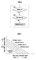
- step S3 the ECU 108 determines if the parking lights are on. If emergency braking is detected and the parking lights are determined to be on ("Yes" in step S3), the ECU 108 sets the brake operation threshold value (emergency braking threshold value) that serves as the condition for retracting the webbing 102 to a threshold value B. If the parking lights are not on (“No" in step S3), the ECU 108 sets the brake operation threshold value (emergency braking threshold value) that serves as the condition for retracting the webbing 102 to a threshold value A.
- the brake operation threshold value emergency braking threshold value
- Figure 7 is a characteristic diagram illustrating the relationship between the depression amount of the brake pedal 106, the depression speed of the brake pedal 106, and the threshold value used for retracting webbing 102.
- the threshold value B is used, the webbing 102 is retracted at a smaller brake pedal depression amount than when the threshold value A is used.
- the webbing 102 is retracted early and the passenger restraining performance can be improved.
- the flowchart of Figure 4 shows the processing by which the brake operation threshold value for retracting the webbing 102 is revised in response to the wipers ON signal obtained from the wiper switch 110.
- the steps preceding step S13 are the same as steps S1 and S2 of Figure 3 and are omitted from the figure.
- the ECU 108 determines that the wipers are on in step S13, it sets the brake operation threshold value that serves as the condition for retracting the webbing 102 to a threshold value C. If the ECU 108 determines that the wipers are not on, it sets the brake operation threshold value that serves as the condition for retracting the webbing 102 to a threshold value A.
- the brake operation threshold value is revised from the threshold value A to the threshold value C as shown in Figure 7 and, as a result, the webbing 102 is retracted at a smaller depression amount of the brake pedal 106.
- the threshold value C the webbing 102 is retracted early and the passenger can be restrained at a more appropriate timing.
- the flowchart of Figure 5 shows the processing by which the brake operation threshold value for retracting the webbing 102 is revised in response to the headlights ON signal obtained from the headlight switch 111.
- the steps preceding step S23 are the same as steps S1 and S2 of Figure 3 and are omitted from the figure.
- the ECU 108 detects that the headlights are on in step S23, it sets the brake operation threshold value that serves as the condition for retracting the webbing 102 to a threshold value D. If the ECU 108 determines that the headlights are not on, it sets the brake operation threshold value that serves as the condition for retracting the webbing 102 to the threshold value A.
- the brake operation threshold value is revised from the threshold value A to the threshold value D as shown in Figure 7 and, as a result, the webbing 102 is retracted at a smaller depression amount of the brake pedal 106.
- the threshold value D the webbing 102 is retracted early and the passenger can be restrained at a more appropriate liming.
- the flowchart of Figure 6 shows the processing by which the brake operation threshold value for retracting the webbing 102 is revised in response to the wipers ON signal obtained from the wiper switch 110 and the headlights ON signal obtained from the headlight switch 111.
- the steps preceding step S33 are the same as steps S1 and S2 of Figure 3 and are omitted from the figure.
- the ECU 108 detects that the wipers are on in step S33 and the headlights are on in step S34, it sets the brake operation threshold value that serves as the condition for retracting the webbing 102 early to a threshold value E.
- the brake operation threshold value set to the threshold value E as shown in Figure 7 and, as a result, the webbing 102 is retracted at a smaller depression amount of the brake pedal 106.
- the threshold value E the webbing 102 is retracted early and the passenger can be restrained at a more appropriate timing.
- a passenger protection device 100 in accordance with the present embodiment can revise the brake operation threshold value used to retract the webbing 102 based on safety related information that includes, but not limited to, the on/off status of the parking lights, the windshield wipers, and the headlights.
- the threshold value can be set to a value well-suited to the quality of the outside visibility and the webbing 102 can be retracted based on the threshold value.
- the passenger can be restrained at an even more appropriate timing.
- the threshold value is set to a lower value such that the webbing 102 is retracted at an even smaller depression amount of the brake pedal 106. As a result, the passenger can be restrained at an even more appropriate timing.
- the brake operation threshold value is set to the threshold value A, which is the largest value.
- the threshold value A which is the largest value.
- the present invention is not limited to such a feature and it is also feasible for these threshold values to be the same.
- the flowchart of Figure 6 presents a case in which the brake operation threshold value is set to a threshold value E that is lower than the threshold values B, C, and D when it is detected that both the wipers and the headlights are on, it is also feasible to set the brake operation threshold value to a value lower than the threshold values B, C, and D when it is detected that both the wipers and the parking lights are on.
- the wipers ON signal is issued from a wiper switch 110 and the headlights ON and parking lights ON signals are issued from a headlight switch 111, it is also feasible to detect the actual operation of the wipers and use the resulting detection signal as the wipers ON signal and to detect the illumination of the headlights and parking lights and use the respective resulting detection signals as headlights ON and parking lights ON signals.
- a passenger protection device in accordance with the first embodiment takes the visibility of the vehicles surroundings into consideration and makes it possible to retract the seatbelt at an appropriate timing.
- FIG. 8 is diagrammatic view for explaining a second embodiment of a passenger protection device in accordance with the present invention. Descriptions of parts that are the same as those of the first embodiment are omitted.
- a brake pedal 106, a brake pedal sensor 107 configured to detect the movement of the brake pedal 106, an accelerator pedal 113, and an accelerator pedal sensor 109 configured to detect the movement of the accelerator pedal 109 are provided at the feet of the passenger P.
- the information detected by the brake pedal sensor 107 includes the timing at which the driver starts depressing the brake pedal, the amount by which the brake pedal is depressed, the speed at which the brake pedal is depressed, and other such information related to the movement of the brake pedal 106.
- the information detected by the accelerator pedal sensor 109 includes the amount by which the accelerator pedal is depressed, the timing at which the driver starts releasing the accelerator pedal, the speed at which the accelerator pedal is released, and other such information related to the movement of the accelerator pedal 113.
- the passenger protection device 100 of the second embodiment is provided with an ECU 108 configured to control the electric motor 104 used for driving the webbing 102.
- the ECU 108 is receives the following signals in this embodiment a brake signal obtained from the brake pedal sensor 107, an accelerator signal obtained from the accelerator pedal sensor 109, and a detection signal obtained from the buckle switch 112 (which detects if the tongue is inserted into the inner buckle 105). Also, a vehicle speed signal is obtained from a vehicle speed detecting device (not shown) installed on the vehicle.
- the ECU 108 determines that an emergency brake operation has occurred and operates the electric motor 104 so as to retract the webbing 102 and restrain the passenger P.
- the pedal switch time i.e., the amount of time from when the driver starts releasing the accelerator pedal 113 until the driver starts depressing the brake pedal 106
- the motor operation threshold value is set to a lower value in order to increase the sensitivity with which emergency braking is detected, thereby enabling an emergency brake operation to be detected with a smaller the depression amount of the brake pedal 106 or a slower depression speed.
- step S51 of Figure 11 the ECU 108 determines if the buckle switch 112 is on or off (based on the detection signal thereof) in order to detect if the seatbelt is fastened, i.e., if the seatbelt is being worn with the tongue inserted into the inner buckle 105. If the seatbelt is not fastened, the ECU 108 repeats step S51. If the seatbelt is fastened, the ECU 108 proceeds to step S52.
- step S53 the ECU 108 determines if the acquired release speed and release amount of the accelerator pedal 113 are equal to or larger than prescribed values. If the release speed and release amount of the accelerator pedal 113 are less than prescribed values, the ECU 108 determines that an emergency brake operation has not been detected and returns to step S51. If the release speed and release amount of the accelerator pedal 113 are equal to or larger than prescribed values, the ECU 108 determines that an emergency brake operation has been detected and proceeds to step S54.
- the motor operation threshold values are shown on a plot in which the vertical axis indicates the depression speed of the brake pedal 106 and the horizontal axis indicates the depression amount of the brake pedal 106.
- the ECR 108 determines that an emergency brake operation has occurred and operates the electric motor 104 so that the webbing 102 is retracted and the passenger P is restrained.
- the motor operation threshold values are shown on a plot in which the vertical axis indicates the pedal switch time, i.e., the amount of time from when the driver starts releasing the accelerator pedal 113 until the driver starts depressing the brake pedal 106, or the release speed the accelerator pedal 113 and the horizontal axis indicates the depression amount of the brake pedal 106.
- the motor operation threshold value is set as a linear function of the vertical axis variable (i.e., the pedal switch time or accelerator pedal release speed).
- the motor operation threshold value is set in a linear fashion with respect to the pedal switch time or the accelerator pedal release speed in such a manner that the shorter the pedal switch time or the faster the accelerator pedal 113 release speed is, the lower the motor operation threshold value is set.
- the revision processing executed by the ECU 108 is digital processing and the straight line shown sloping down and to the right in the lower portion of Figure 12 would be more accurately depicted as step-like graph. However, it is possible to approach a continuous straight line by revising the motor operation threshold value in finer increments by preparing a larger number of present threshold values (A, B, C, D, E, F, etc.).
- Figure 13 illustrates the second setting method in which the motor operation threshold value is set as a higher order function of the pedal switch time, i.e., the amount of time from when the driver starts releasing the accelerator pedal 113 until the driver starts depressing the brake pedal 106, or the release speed the accelerator pedal 113.
- the upper portion of Figure 13 is the same as the upper portion of Figure 12.
- the motor operation threshold values are shown on a plot in which the vertical axis indicates the pedal switch time, i.e., the amount of time from when the driver starts releasing the accelerator pedal 113 until the driver starts depressing the brake pedal 106, or the release speed the accelerator pedal 113 and the horizontal axis indicates the depression amount of the brake pedal 106.
- the motor operation threshold value is set as a higher order (curved) function of the vertical axis variable (i.e., the pedal switch time or accelerator pedal release speed).
- the motor operation threshold value is set in a curved fashion with respect to the pedal switch time or the accelerator pedal release speed in such a manner that the motor operation threshold value becomes gradually smaller when the pedal switch time or accelerator release speed is comparatively slow and becomes smaller more rapidly when the pedal switch time or accelerator release speed is comparatively fast.
- the revision processing is digital processing executed by the ECU 108 and the straight line shown sloping down and to the right in the lower portion of Figure 12 would be more accurately depicted as step-like graph. However, it is possible to approach a continuous straight line by revising the motor operation threshold value A, B, C, and D in finer increments.
- a passenger protection device in accordance with the second embodiment is a passenger protection device configured to operate an electric motor 104 so as to retract the webbing 102 of a seatbelt and restrain a passenger when a detection value based on safety related information exceeds a motor operation threshold value, said safety related information including such vehicle driving operations as operation of the accelerator pedal and brake pedal.
- an ECU (controller) 108 Based on detection information from an accelerator pedal sensor 109 and a brake pedal sensor 107, an ECU (controller) 108revises the motor operation threshold value in accordance with the timing at which the driver starts releasing the accelerator pedal 113 and the timing at which the driver starts depressing the brake pedal 106.
- emergency braking can be detected earlier and more accurately in accordance with the driving conditions and the timing at which the webbing 102 of the seatbelt is retracted can be advanced by revising the motor operation threshold value to a lower value. As a result, the forward movement experienced by the passenger in a collision can be reduced.
- the ECU 108 uses detection information from the accelerator pedal sensor 109 and the brake pedal sensor 107 to revise the motor operation threshold value in such a manner that the shorter the pedal switch time, i.e., the shorter the difference between the timing at which the driver starts releasing the accelerator pedal 113 and the timing at which the driver starts depressing the brake pedal 106, the smaller the value to which the motor operation threshold value is revised; or the ECU 108 uses detection information from the accelerator pedal sensor 109 to revise the motor operation threshold value in such a manner that the faster the speed at which the accelerator pedal 113 is released, the smaller the value to which the motor operation threshold value is revised.
- this embodiment increases the sensitivity with which emergency braking is detected and advances the timing at which the webbing is retracted only when it is highly probable that an emergency brake operation will occur. As a result, a high degree of passenger protection is achieved while also reducing the annoyance associated with emergency braking so that degradation of the passenger's comfort is avoided
- the motor operation threshold value is set as a linear function or higher order function of the release speed of the accelerator pedal 113 or the pedal switch time, which is the amount of time from when the driver starts releasing the accelerator pedal 113 until the driver starts depressing the brake pedal 106.
- the function used to revise the motor operation threshold value can be changed in accordance with the road conditions and driving conditions and emergency braking can be detected earlier and more accurately in accordance with the driving conditions.
- the ECU 108 uses the depression amount and depression speed of the brake pedal 106 as the aforementioned detection values based on vehicle driving operations for determining if the passenger should be restrained by operating the motor 104 and retracting the webbing 102
- the invention is not limited to such an approach. It is also acceptable to use detection information from the accelerator pedal sensor 109, information regarding the steering angle of the steering wheel 10, the vehicle speed, a combination of these, or a combination of one or more of these including the detection information from the brake pedal sensor 107.
- detection information from the accelerator pedal sensor and the brake pedal sensor are used to revise the motor operation threshold value in accordance with the timing at which the driver starts releasing the accelerator pedal 113 and the timing at which the driver starts depressing the brake pedal 106.
- the second embodiment can detect emergency braking earlier and more accurately in accordance with the driving conditions and the timing at which the webbing of the seatbelt is retracted can be advanced by revising the motor operation threshold value to a lower value. As a result, the forward movement experienced by the passenger in a collision can be reduced.
- the second embodiment increases the sensitivity with which emergency braking is detected and advances the timing at which the webbing is retracted only when it is highly probable that an emergency brake operation will occur. As a result, a high degree of passenger protection is achieved while also reducing the annoyance associated with emergency braking so that degradation of the passenger's comfort is avoided.
Landscapes
- Engineering & Computer Science (AREA)
- Mechanical Engineering (AREA)
- Automotive Seat Belt Assembly (AREA)
- Auxiliary Drives, Propulsion Controls, And Safety Devices (AREA)
- Valves And Accessory Devices For Braking Systems (AREA)
Priority Applications (1)
| Application Number | Priority Date | Filing Date | Title |
|---|---|---|---|
| EP08001519A EP1939046B1 (fr) | 2003-10-29 | 2004-10-01 | Dispositif de protection de passager |
Applications Claiming Priority (4)
| Application Number | Priority Date | Filing Date | Title |
|---|---|---|---|
| JP2003369253 | 2003-10-29 | ||
| JP2003369253A JP3891169B2 (ja) | 2003-10-29 | 2003-10-29 | 乗員保護装置 |
| JP2003405941 | 2003-12-04 | ||
| JP2003405941A JP3891173B2 (ja) | 2003-12-04 | 2003-12-04 | 乗員保護装置 |
Related Child Applications (1)
| Application Number | Title | Priority Date | Filing Date |
|---|---|---|---|
| EP08001519A Division EP1939046B1 (fr) | 2003-10-29 | 2004-10-01 | Dispositif de protection de passager |
Publications (3)
| Publication Number | Publication Date |
|---|---|
| EP1527960A2 true EP1527960A2 (fr) | 2005-05-04 |
| EP1527960A3 EP1527960A3 (fr) | 2006-06-21 |
| EP1527960B1 EP1527960B1 (fr) | 2008-09-10 |
Family
ID=34425404
Family Applications (2)
| Application Number | Title | Priority Date | Filing Date |
|---|---|---|---|
| EP04256089A Expired - Fee Related EP1527960B1 (fr) | 2003-10-29 | 2004-10-01 | Dispositif de protection des occupants |
| EP08001519A Expired - Fee Related EP1939046B1 (fr) | 2003-10-29 | 2004-10-01 | Dispositif de protection de passager |
Family Applications After (1)
| Application Number | Title | Priority Date | Filing Date |
|---|---|---|---|
| EP08001519A Expired - Fee Related EP1939046B1 (fr) | 2003-10-29 | 2004-10-01 | Dispositif de protection de passager |
Country Status (4)
| Country | Link |
|---|---|
| US (1) | US7720585B2 (fr) |
| EP (2) | EP1527960B1 (fr) |
| CN (1) | CN100336687C (fr) |
| DE (1) | DE602004016439D1 (fr) |
Cited By (1)
| Publication number | Priority date | Publication date | Assignee | Title |
|---|---|---|---|---|
| WO2005108173A1 (fr) * | 2004-04-30 | 2005-11-17 | Daimlerchrysler Ag | Procede pour commander un composant de vehicule automobile influant sur la securite, et vehicule automobile comportant un systeme de securite a declenchement preventif |
Families Citing this family (11)
| Publication number | Priority date | Publication date | Assignee | Title |
|---|---|---|---|---|
| JP3908159B2 (ja) * | 2002-11-29 | 2007-04-25 | アイシン精機株式会社 | 乗員判定装置 |
| JP4714525B2 (ja) * | 2005-08-05 | 2011-06-29 | タカタ株式会社 | シートベルトリトラクタ、シートベルト装置、シートベルト装置付車両 |
| JP2007106745A (ja) * | 2005-09-16 | 2007-04-26 | Bayer Cropscience Ag | スルホンアニリド類の除草剤としての利用 |
| JP4375372B2 (ja) * | 2006-08-31 | 2009-12-02 | 株式会社日立製作所 | シートベルトリトラクタ装置 |
| JP4285569B2 (ja) * | 2007-08-13 | 2009-06-24 | トヨタ自動車株式会社 | 乗員保護装置 |
| US7520533B1 (en) * | 2008-08-28 | 2009-04-21 | Orin Skaurud | Seat belt controlled ignition system |
| JP5715454B2 (ja) * | 2011-03-15 | 2015-05-07 | 富士重工業株式会社 | 車両の運転支援装置 |
| DE102011084204A1 (de) * | 2011-10-10 | 2013-04-11 | Robert Bosch Gmbh | Verfahren zum Ansteuern von Sicherheitsaktuatorik eines Kraftfahrzeugs |
| DE102016213130A1 (de) * | 2016-07-19 | 2018-01-25 | Robert Bosch Gmbh | Verfahren zum Ansteuern eines Personenschutzsystems eines Fahrzeugs und Steuergerät |
| US10875435B1 (en) * | 2017-03-30 | 2020-12-29 | Zoox, Inc. | Headrest with passenger flaps |
| USD885280S1 (en) | 2017-03-30 | 2020-05-26 | Zoox, Inc. | Vehicle headrest |
Citations (3)
| Publication number | Priority date | Publication date | Assignee | Title |
|---|---|---|---|---|
| DE19749857A1 (de) * | 1997-11-11 | 1999-05-20 | Siemens Ag | Verfahren und Vorrichtung zum Umschalten des Betriebszustandes eines Steuergerätes für Rückhaltesysteme aus einem Bereitschaftszustand in einen Aktivzustand |
| US20030178836A1 (en) * | 2002-03-22 | 2003-09-25 | Viano David Charles | Seat belt retractor system |
| EP1415872A1 (fr) * | 2002-10-31 | 2004-05-06 | Nissan Motor Co., Ltd. | Ceinture de sécurité pour véhicule |
Family Cites Families (38)
| Publication number | Priority date | Publication date | Assignee | Title |
|---|---|---|---|---|
| US7164117B2 (en) * | 1992-05-05 | 2007-01-16 | Automotive Technologies International, Inc. | Vehicular restraint system control system and method using multiple optical imagers |
| US7663502B2 (en) * | 1992-05-05 | 2010-02-16 | Intelligent Technologies International, Inc. | Asset system control arrangement and method |
| JPH06255389A (ja) * | 1991-02-26 | 1994-09-13 | Mitsubishi Electric Corp | 車両の走行制御装置 |
| JP2946995B2 (ja) * | 1993-03-31 | 1999-09-13 | 日産自動車株式会社 | 乗物用シートベルト装置 |
| DE4314883A1 (de) * | 1993-05-05 | 1994-11-10 | Trw Repa Gmbh | Sicherheitsgurtaufroller |
| JPH07137560A (ja) * | 1993-11-19 | 1995-05-30 | Aisin Seiki Co Ltd | 車両駆動出力制御装置 |
| US5477940A (en) * | 1995-01-09 | 1995-12-26 | Charles Brister | Accelerator pedal override apparatus for self-propelled motorized cart with aligned brake and accelerator pushrod type operator pedals |
| US5913378A (en) * | 1995-01-09 | 1999-06-22 | Charles Brister | Accelerator pedal override apparatus for self-propelled motorized cart with aligned brake and accelerator pushrod type operator pedals |
| US5558370A (en) * | 1995-03-30 | 1996-09-24 | Automotive Systems Laboratory, Inc. | Electronic seat belt tensioning system |
| US5995892A (en) * | 1995-06-12 | 1999-11-30 | Denso Corporation | Triggering device for safety apparatus |
| JP4142750B2 (ja) * | 1995-09-08 | 2008-09-03 | タカタ株式会社 | 車両の乗員拘束保護システム |
| JP3402889B2 (ja) * | 1996-01-11 | 2003-05-06 | キヤノン株式会社 | インクジェットヘッドの組立装置および組立方法 |
| US5765774A (en) * | 1996-04-05 | 1998-06-16 | Takata Corporation | Seat belt retractor employing ultrasonic motor |
| JPH10141496A (ja) * | 1996-10-25 | 1998-05-29 | Aqueous Res:Kk | 車両制御装置 |
| DE29704974U1 (de) * | 1997-03-18 | 1997-07-17 | Trw Repa Gmbh | Gurtaufroller für einen Fahrzeug-Sicherheitsgurt |
| DE19817326A1 (de) * | 1998-04-18 | 1999-10-21 | Continental Teves Ag & Co Ohg | Verfahren zum Verkürzen des Bremsgeweges |
| KR100258326B1 (ko) * | 1998-05-18 | 2000-08-01 | 이형찬 | 차량용 리트렉터 |
| JP3946366B2 (ja) * | 1998-11-27 | 2007-07-18 | 本田技研工業株式会社 | 乗員拘束装置およびその制御方法 |
| JP3865182B2 (ja) | 1998-12-25 | 2007-01-10 | タカタ株式会社 | シートベルトシステム |
| JP4467688B2 (ja) * | 1999-01-19 | 2010-05-26 | タカタ株式会社 | シートベルト巻取装置 |
| DE19935248C1 (de) * | 1999-07-27 | 2000-10-12 | Daimler Chrysler Ag | Sicherheitsgurtsystem |
| JP2001151076A (ja) * | 1999-11-29 | 2001-06-05 | Takata Corp | 乗員拘束保護システム |
| DE19957814C2 (de) * | 1999-12-01 | 2003-07-31 | Trw Automotive Electron & Comp | Gurtaufrollersystem |
| JP4599649B2 (ja) * | 2000-03-09 | 2010-12-15 | 株式会社エクォス・リサーチ | データ通信ネットワークにおける課金処理装置 |
| JP2001253317A (ja) | 2000-03-14 | 2001-09-18 | Takata Corp | シートベルトシステム |
| DE10029061C2 (de) * | 2000-06-13 | 2003-12-11 | Breed Automotive Tech | Rückhaltevorrichtung |
| JP3727515B2 (ja) * | 2000-07-12 | 2005-12-14 | 株式会社東海理化電機製作所 | ウエビング巻取装置 |
| GB2370130B (en) * | 2000-10-11 | 2004-10-06 | Ford Motor Co | A control system for a hybrid electric vehicle |
| DE10061040A1 (de) * | 2000-12-08 | 2002-06-13 | Daimler Chrysler Ag | Verfahren zur Ansteuerung eines reversiblen Gurtstraffers |
| JP2003040078A (ja) * | 2001-08-01 | 2003-02-13 | Denso Corp | エアバッグ作動制御システム |
| JP3988600B2 (ja) * | 2001-12-14 | 2007-10-10 | 日産自動車株式会社 | 乗員拘束システム |
| JP3575475B2 (ja) * | 2002-05-10 | 2004-10-13 | 日産自動車株式会社 | 車両用シートベルト装置 |
| JP3562519B2 (ja) * | 2002-09-30 | 2004-09-08 | 日産自動車株式会社 | 車両用シートベルト装置 |
| JP3815420B2 (ja) * | 2002-10-24 | 2006-08-30 | トヨタ自動車株式会社 | 車両の乗員保護装置 |
| JP3966161B2 (ja) * | 2002-10-31 | 2007-08-29 | 日産自動車株式会社 | 車両用シートベルト装置 |
| JP4244213B2 (ja) * | 2002-12-26 | 2009-03-25 | 株式会社デンソー | 車両用安全装置 |
| JP4515053B2 (ja) * | 2003-07-23 | 2010-07-28 | 株式会社トランストロン | ブレーキ液圧保持装置 |
| DE10338760A1 (de) * | 2003-08-23 | 2005-03-17 | Daimlerchrysler Ag | Kraftfahrzeug mit einem Pre-Safe-System |
-
2004
- 2004-10-01 EP EP04256089A patent/EP1527960B1/fr not_active Expired - Fee Related
- 2004-10-01 EP EP08001519A patent/EP1939046B1/fr not_active Expired - Fee Related
- 2004-10-01 DE DE602004016439T patent/DE602004016439D1/de active Active
- 2004-10-28 US US10/975,073 patent/US7720585B2/en not_active Expired - Fee Related
- 2004-10-29 CN CNB2004100896843A patent/CN100336687C/zh not_active Expired - Fee Related
Patent Citations (3)
| Publication number | Priority date | Publication date | Assignee | Title |
|---|---|---|---|---|
| DE19749857A1 (de) * | 1997-11-11 | 1999-05-20 | Siemens Ag | Verfahren und Vorrichtung zum Umschalten des Betriebszustandes eines Steuergerätes für Rückhaltesysteme aus einem Bereitschaftszustand in einen Aktivzustand |
| US20030178836A1 (en) * | 2002-03-22 | 2003-09-25 | Viano David Charles | Seat belt retractor system |
| EP1415872A1 (fr) * | 2002-10-31 | 2004-05-06 | Nissan Motor Co., Ltd. | Ceinture de sécurité pour véhicule |
Cited By (1)
| Publication number | Priority date | Publication date | Assignee | Title |
|---|---|---|---|---|
| WO2005108173A1 (fr) * | 2004-04-30 | 2005-11-17 | Daimlerchrysler Ag | Procede pour commander un composant de vehicule automobile influant sur la securite, et vehicule automobile comportant un systeme de securite a declenchement preventif |
Also Published As
| Publication number | Publication date |
|---|---|
| US20050096818A1 (en) | 2005-05-05 |
| EP1939046A1 (fr) | 2008-07-02 |
| EP1939046B1 (fr) | 2011-12-14 |
| US7720585B2 (en) | 2010-05-18 |
| EP1527960B1 (fr) | 2008-09-10 |
| CN100336687C (zh) | 2007-09-12 |
| EP1527960A3 (fr) | 2006-06-21 |
| DE602004016439D1 (de) | 2008-10-23 |
| CN1611393A (zh) | 2005-05-04 |
Similar Documents
| Publication | Publication Date | Title |
|---|---|---|
| EP1456065B1 (fr) | Dispositif a ceinture de securite et procede de commande d'une ceinture de securite | |
| US6758495B2 (en) | Method and safety restraint device for restraining an occupant on a vehicle seat | |
| EP1527960B1 (fr) | Dispositif de protection des occupants | |
| US7299119B2 (en) | Seat belt system having occupant sensing device | |
| EP1592587B1 (fr) | Dispositif de ceinture de securite | |
| US10562490B2 (en) | Occupant restraining device for vehicle | |
| EP2407343A1 (fr) | Dispositif de réglage de la position d'un appui-tête et procédé associé | |
| US20020171542A1 (en) | Anti-collision safety system for vehicle | |
| JP4669509B2 (ja) | 車両における乗員保護手段の制御方法及び乗員保護システム | |
| US7698037B2 (en) | Seatbelt device for vehicle | |
| US20090024282A1 (en) | Method for a Preventive-Action Protection System In a Motor Vehicle Having an Inter-Vehicle Distance Sensor System | |
| US20070296193A1 (en) | Safety Device for a Motor Vehicle | |
| US7438150B2 (en) | Seat belt apparatus | |
| EP2505438B1 (fr) | Actionnement d'un dispositif actif de véhicule pendant le freinage | |
| JP2001253317A (ja) | シートベルトシステム | |
| US7568542B2 (en) | Occupant protection device | |
| JP2005081964A (ja) | 電動パーキングブレーキシステム | |
| JP3891169B2 (ja) | 乗員保護装置 | |
| JP3891173B2 (ja) | 乗員保護装置 | |
| KR100353942B1 (ko) | 자동차의 급제동시 탑승자 안전성 확보장치 | |
| KR20020047411A (ko) | 자동차의 시트벨트를 이용한 과속방지장치 | |
| KR19980021122U (ko) | 차량의 안전벨트 제어구조 |
Legal Events
| Date | Code | Title | Description |
|---|---|---|---|
| PUAI | Public reference made under article 153(3) epc to a published international application that has entered the european phase |
Free format text: ORIGINAL CODE: 0009012 |
|
| 17P | Request for examination filed |
Effective date: 20041011 |
|
| AK | Designated contracting states |
Kind code of ref document: A2 Designated state(s): AT BE BG CH CY CZ DE DK EE ES FI FR GB GR HU IE IT LI LU MC NL PL PT RO SE SI SK TR |
|
| AX | Request for extension of the european patent |
Extension state: AL HR LT LV MK |
|
| PUAL | Search report despatched |
Free format text: ORIGINAL CODE: 0009013 |
|
| AK | Designated contracting states |
Kind code of ref document: A3 Designated state(s): AT BE BG CH CY CZ DE DK EE ES FI FR GB GR HU IE IT LI LU MC NL PL PT RO SE SI SK TR |
|
| AX | Request for extension of the european patent |
Extension state: AL HR LT LV MK |
|
| 17Q | First examination report despatched |
Effective date: 20061110 |
|
| AKX | Designation fees paid |
Designated state(s): DE FR GB |
|
| GRAP | Despatch of communication of intention to grant a patent |
Free format text: ORIGINAL CODE: EPIDOSNIGR1 |
|
| GRAS | Grant fee paid |
Free format text: ORIGINAL CODE: EPIDOSNIGR3 |
|
| GRAA | (expected) grant |
Free format text: ORIGINAL CODE: 0009210 |
|
| AK | Designated contracting states |
Kind code of ref document: B1 Designated state(s): DE FR GB |
|
| REG | Reference to a national code |
Ref country code: GB Ref legal event code: FG4D |
|
| REF | Corresponds to: |
Ref document number: 602004016439 Country of ref document: DE Date of ref document: 20081023 Kind code of ref document: P |
|
| PLBE | No opposition filed within time limit |
Free format text: ORIGINAL CODE: 0009261 |
|
| STAA | Information on the status of an ep patent application or granted ep patent |
Free format text: STATUS: NO OPPOSITION FILED WITHIN TIME LIMIT |
|
| 26N | No opposition filed |
Effective date: 20090611 |
|
| REG | Reference to a national code |
Ref country code: FR Ref legal event code: PLFP Year of fee payment: 13 |
|
| REG | Reference to a national code |
Ref country code: FR Ref legal event code: PLFP Year of fee payment: 14 |
|
| REG | Reference to a national code |
Ref country code: FR Ref legal event code: PLFP Year of fee payment: 15 |
|
| PGFP | Annual fee paid to national office [announced via postgrant information from national office to epo] |
Ref country code: FR Payment date: 20180813 Year of fee payment: 15 |
|
| PGFP | Annual fee paid to national office [announced via postgrant information from national office to epo] |
Ref country code: GB Payment date: 20180926 Year of fee payment: 15 |
|
| PGFP | Annual fee paid to national office [announced via postgrant information from national office to epo] |
Ref country code: DE Payment date: 20180918 Year of fee payment: 15 |
|
| REG | Reference to a national code |
Ref country code: DE Ref legal event code: R119 Ref document number: 602004016439 Country of ref document: DE |
|
| PG25 | Lapsed in a contracting state [announced via postgrant information from national office to epo] |
Ref country code: DE Free format text: LAPSE BECAUSE OF NON-PAYMENT OF DUE FEES Effective date: 20200501 |
|
| GBPC | Gb: european patent ceased through non-payment of renewal fee |
Effective date: 20191001 |
|
| PG25 | Lapsed in a contracting state [announced via postgrant information from national office to epo] |
Ref country code: GB Free format text: LAPSE BECAUSE OF NON-PAYMENT OF DUE FEES Effective date: 20191001 Ref country code: FR Free format text: LAPSE BECAUSE OF NON-PAYMENT OF DUE FEES Effective date: 20191031 |