EP1527936A1 - Essieu d'entraínement pour véhicule automobile et procédé de sa fabrication - Google Patents
Essieu d'entraínement pour véhicule automobile et procédé de sa fabrication Download PDFInfo
- Publication number
- EP1527936A1 EP1527936A1 EP04105402A EP04105402A EP1527936A1 EP 1527936 A1 EP1527936 A1 EP 1527936A1 EP 04105402 A EP04105402 A EP 04105402A EP 04105402 A EP04105402 A EP 04105402A EP 1527936 A1 EP1527936 A1 EP 1527936A1
- Authority
- EP
- European Patent Office
- Prior art keywords
- differential
- support beam
- beam member
- plate section
- central plate
- Prior art date
- Legal status (The legal status is an assumption and is not a legal conclusion. Google has not performed a legal analysis and makes no representation as to the accuracy of the status listed.)
- Withdrawn
Links
Images


Classifications
-
- B—PERFORMING OPERATIONS; TRANSPORTING
- B60—VEHICLES IN GENERAL
- B60K—ARRANGEMENT OR MOUNTING OF PROPULSION UNITS OR OF TRANSMISSIONS IN VEHICLES; ARRANGEMENT OR MOUNTING OF PLURAL DIVERSE PRIME-MOVERS IN VEHICLES; AUXILIARY DRIVES FOR VEHICLES; INSTRUMENTATION OR DASHBOARDS FOR VEHICLES; ARRANGEMENTS IN CONNECTION WITH COOLING, AIR INTAKE, GAS EXHAUST OR FUEL SUPPLY OF PROPULSION UNITS IN VEHICLES
- B60K17/00—Arrangement or mounting of transmissions in vehicles
- B60K17/04—Arrangement or mounting of transmissions in vehicles characterised by arrangement, location, or kind of gearing
- B60K17/16—Arrangement or mounting of transmissions in vehicles characterised by arrangement, location, or kind of gearing of differential gearing
- B60K17/165—Arrangement or mounting of transmissions in vehicles characterised by arrangement, location, or kind of gearing of differential gearing provided between independent half axles
-
- B—PERFORMING OPERATIONS; TRANSPORTING
- B60—VEHICLES IN GENERAL
- B60B—VEHICLE WHEELS; CASTORS; AXLES FOR WHEELS OR CASTORS; INCREASING WHEEL ADHESION
- B60B35/00—Axle units; Parts thereof ; Arrangements for lubrication of axles
- B60B35/12—Torque-transmitting axles
- B60B35/16—Axle housings
-
- B—PERFORMING OPERATIONS; TRANSPORTING
- B60—VEHICLES IN GENERAL
- B60K—ARRANGEMENT OR MOUNTING OF PROPULSION UNITS OR OF TRANSMISSIONS IN VEHICLES; ARRANGEMENT OR MOUNTING OF PLURAL DIVERSE PRIME-MOVERS IN VEHICLES; AUXILIARY DRIVES FOR VEHICLES; INSTRUMENTATION OR DASHBOARDS FOR VEHICLES; ARRANGEMENTS IN CONNECTION WITH COOLING, AIR INTAKE, GAS EXHAUST OR FUEL SUPPLY OF PROPULSION UNITS IN VEHICLES
- B60K17/00—Arrangement or mounting of transmissions in vehicles
- B60K17/04—Arrangement or mounting of transmissions in vehicles characterised by arrangement, location, or kind of gearing
- B60K17/16—Arrangement or mounting of transmissions in vehicles characterised by arrangement, location, or kind of gearing of differential gearing
-
- F—MECHANICAL ENGINEERING; LIGHTING; HEATING; WEAPONS; BLASTING
- F16—ENGINEERING ELEMENTS AND UNITS; GENERAL MEASURES FOR PRODUCING AND MAINTAINING EFFECTIVE FUNCTIONING OF MACHINES OR INSTALLATIONS; THERMAL INSULATION IN GENERAL
- F16H—GEARING
- F16H48/00—Differential gearings
- F16H48/06—Differential gearings with gears having orbital motion
- F16H48/08—Differential gearings with gears having orbital motion comprising bevel gears
-
- F—MECHANICAL ENGINEERING; LIGHTING; HEATING; WEAPONS; BLASTING
- F16—ENGINEERING ELEMENTS AND UNITS; GENERAL MEASURES FOR PRODUCING AND MAINTAINING EFFECTIVE FUNCTIONING OF MACHINES OR INSTALLATIONS; THERMAL INSULATION IN GENERAL
- F16H—GEARING
- F16H57/00—General details of gearing
- F16H57/02—Gearboxes; Mounting gearing therein
- F16H57/021—Shaft support structures, e.g. partition walls, bearing eyes, casing walls or covers with bearings
-
- B—PERFORMING OPERATIONS; TRANSPORTING
- B60—VEHICLES IN GENERAL
- B60B—VEHICLE WHEELS; CASTORS; AXLES FOR WHEELS OR CASTORS; INCREASING WHEEL ADHESION
- B60B2310/00—Manufacturing methods
- B60B2310/20—Shaping
- B60B2310/202—Shaping by casting
-
- B—PERFORMING OPERATIONS; TRANSPORTING
- B60—VEHICLES IN GENERAL
- B60B—VEHICLE WHEELS; CASTORS; AXLES FOR WHEELS OR CASTORS; INCREASING WHEEL ADHESION
- B60B2310/00—Manufacturing methods
- B60B2310/20—Shaping
- B60B2310/206—Shaping by stamping
-
- B—PERFORMING OPERATIONS; TRANSPORTING
- B60—VEHICLES IN GENERAL
- B60B—VEHICLE WHEELS; CASTORS; AXLES FOR WHEELS OR CASTORS; INCREASING WHEEL ADHESION
- B60B2310/00—Manufacturing methods
- B60B2310/20—Shaping
- B60B2310/208—Shaping by forging
-
- B—PERFORMING OPERATIONS; TRANSPORTING
- B60—VEHICLES IN GENERAL
- B60B—VEHICLE WHEELS; CASTORS; AXLES FOR WHEELS OR CASTORS; INCREASING WHEEL ADHESION
- B60B2310/00—Manufacturing methods
- B60B2310/30—Manufacturing methods joining
- B60B2310/302—Manufacturing methods joining by welding
-
- B—PERFORMING OPERATIONS; TRANSPORTING
- B60—VEHICLES IN GENERAL
- B60B—VEHICLE WHEELS; CASTORS; AXLES FOR WHEELS OR CASTORS; INCREASING WHEEL ADHESION
- B60B2310/00—Manufacturing methods
- B60B2310/30—Manufacturing methods joining
- B60B2310/305—Manufacturing methods joining by screwing
-
- B—PERFORMING OPERATIONS; TRANSPORTING
- B60—VEHICLES IN GENERAL
- B60B—VEHICLE WHEELS; CASTORS; AXLES FOR WHEELS OR CASTORS; INCREASING WHEEL ADHESION
- B60B2360/00—Materials; Physical forms thereof
- B60B2360/10—Metallic materials
-
- B—PERFORMING OPERATIONS; TRANSPORTING
- B60—VEHICLES IN GENERAL
- B60B—VEHICLE WHEELS; CASTORS; AXLES FOR WHEELS OR CASTORS; INCREASING WHEEL ADHESION
- B60B2360/00—Materials; Physical forms thereof
- B60B2360/10—Metallic materials
- B60B2360/102—Steel
-
- B—PERFORMING OPERATIONS; TRANSPORTING
- B60—VEHICLES IN GENERAL
- B60B—VEHICLE WHEELS; CASTORS; AXLES FOR WHEELS OR CASTORS; INCREASING WHEEL ADHESION
- B60B2380/00—Bearings
- B60B2380/10—Type
- B60B2380/14—Roller bearings
-
- B—PERFORMING OPERATIONS; TRANSPORTING
- B60—VEHICLES IN GENERAL
- B60B—VEHICLE WHEELS; CASTORS; AXLES FOR WHEELS OR CASTORS; INCREASING WHEEL ADHESION
- B60B2900/00—Purpose of invention
- B60B2900/10—Reduction of
- B60B2900/113—Production or maintenance time
-
- B—PERFORMING OPERATIONS; TRANSPORTING
- B60—VEHICLES IN GENERAL
- B60G—VEHICLE SUSPENSION ARRANGEMENTS
- B60G2206/00—Indexing codes related to the manufacturing of suspensions: constructional features, the materials used, procedures or tools
- B60G2206/01—Constructional features of suspension elements, e.g. arms, dampers, springs
- B60G2206/014—Constructional features of suspension elements, e.g. arms, dampers, springs with reinforcing nerves or branches
-
- B—PERFORMING OPERATIONS; TRANSPORTING
- B60—VEHICLES IN GENERAL
- B60G—VEHICLE SUSPENSION ARRANGEMENTS
- B60G2206/00—Indexing codes related to the manufacturing of suspensions: constructional features, the materials used, procedures or tools
- B60G2206/01—Constructional features of suspension elements, e.g. arms, dampers, springs
- B60G2206/30—Constructional features of rigid axles
- B60G2206/31—Straight axle
-
- F—MECHANICAL ENGINEERING; LIGHTING; HEATING; WEAPONS; BLASTING
- F16—ENGINEERING ELEMENTS AND UNITS; GENERAL MEASURES FOR PRODUCING AND MAINTAINING EFFECTIVE FUNCTIONING OF MACHINES OR INSTALLATIONS; THERMAL INSULATION IN GENERAL
- F16H—GEARING
- F16H48/00—Differential gearings
- F16H48/06—Differential gearings with gears having orbital motion
- F16H48/08—Differential gearings with gears having orbital motion comprising bevel gears
- F16H2048/082—Differential gearings with gears having orbital motion comprising bevel gears characterised by the arrangement of output shafts
-
- F—MECHANICAL ENGINEERING; LIGHTING; HEATING; WEAPONS; BLASTING
- F16—ENGINEERING ELEMENTS AND UNITS; GENERAL MEASURES FOR PRODUCING AND MAINTAINING EFFECTIVE FUNCTIONING OF MACHINES OR INSTALLATIONS; THERMAL INSULATION IN GENERAL
- F16H—GEARING
- F16H48/00—Differential gearings
- F16H48/38—Constructional details
- F16H2048/382—Methods for manufacturing differential gearings
-
- Y—GENERAL TAGGING OF NEW TECHNOLOGICAL DEVELOPMENTS; GENERAL TAGGING OF CROSS-SECTIONAL TECHNOLOGIES SPANNING OVER SEVERAL SECTIONS OF THE IPC; TECHNICAL SUBJECTS COVERED BY FORMER USPC CROSS-REFERENCE ART COLLECTIONS [XRACs] AND DIGESTS
- Y10—TECHNICAL SUBJECTS COVERED BY FORMER USPC
- Y10T—TECHNICAL SUBJECTS COVERED BY FORMER US CLASSIFICATION
- Y10T29/00—Metal working
- Y10T29/49—Method of mechanical manufacture
- Y10T29/49826—Assembling or joining
- Y10T29/4984—Retaining clearance for motion between assembled parts
-
- Y—GENERAL TAGGING OF NEW TECHNOLOGICAL DEVELOPMENTS; GENERAL TAGGING OF CROSS-SECTIONAL TECHNOLOGIES SPANNING OVER SEVERAL SECTIONS OF THE IPC; TECHNICAL SUBJECTS COVERED BY FORMER USPC CROSS-REFERENCE ART COLLECTIONS [XRACs] AND DIGESTS
- Y10—TECHNICAL SUBJECTS COVERED BY FORMER USPC
- Y10T—TECHNICAL SUBJECTS COVERED BY FORMER US CLASSIFICATION
- Y10T29/00—Metal working
- Y10T29/49—Method of mechanical manufacture
- Y10T29/49826—Assembling or joining
- Y10T29/49892—Joining plate edge perpendicularly to frame
-
- Y—GENERAL TAGGING OF NEW TECHNOLOGICAL DEVELOPMENTS; GENERAL TAGGING OF CROSS-SECTIONAL TECHNOLOGIES SPANNING OVER SEVERAL SECTIONS OF THE IPC; TECHNICAL SUBJECTS COVERED BY FORMER USPC CROSS-REFERENCE ART COLLECTIONS [XRACs] AND DIGESTS
- Y10—TECHNICAL SUBJECTS COVERED BY FORMER USPC
- Y10T—TECHNICAL SUBJECTS COVERED BY FORMER US CLASSIFICATION
- Y10T29/00—Metal working
- Y10T29/49—Method of mechanical manufacture
- Y10T29/49826—Assembling or joining
- Y10T29/49893—Peripheral joining of opposed mirror image parts to form a hollow body
-
- Y—GENERAL TAGGING OF NEW TECHNOLOGICAL DEVELOPMENTS; GENERAL TAGGING OF CROSS-SECTIONAL TECHNOLOGIES SPANNING OVER SEVERAL SECTIONS OF THE IPC; TECHNICAL SUBJECTS COVERED BY FORMER USPC CROSS-REFERENCE ART COLLECTIONS [XRACs] AND DIGESTS
- Y10—TECHNICAL SUBJECTS COVERED BY FORMER USPC
- Y10T—TECHNICAL SUBJECTS COVERED BY FORMER US CLASSIFICATION
- Y10T29/00—Metal working
- Y10T29/49—Method of mechanical manufacture
- Y10T29/49826—Assembling or joining
- Y10T29/49947—Assembling or joining by applying separate fastener
- Y10T29/49963—Threaded fastener
-
- Y—GENERAL TAGGING OF NEW TECHNOLOGICAL DEVELOPMENTS; GENERAL TAGGING OF CROSS-SECTIONAL TECHNOLOGIES SPANNING OVER SEVERAL SECTIONS OF THE IPC; TECHNICAL SUBJECTS COVERED BY FORMER USPC CROSS-REFERENCE ART COLLECTIONS [XRACs] AND DIGESTS
- Y10—TECHNICAL SUBJECTS COVERED BY FORMER USPC
- Y10T—TECHNICAL SUBJECTS COVERED BY FORMER US CLASSIFICATION
- Y10T74/00—Machine element or mechanism
- Y10T74/21—Elements
- Y10T74/2186—Gear casings
- Y10T74/2188—Axle and torque tubes
Definitions
- the present invention relates to axle assemblies for motor vehicles and methods for assembling thereof in general, and more particularly to a method for assembling axle assemblies.
- Rigid drive axle assemblies are well known structures that are in common use in most motor vehicles. Such axle assemblies include a number of components that are adapted to transmit rotational power from an engine of the motor vehicle to wheels thereof.
- the rigid drive axle assembly includes a hollow axle housing, a differential, which is rotatably supported within the axle housing by a non-rotating carrier.
- the differential is connected between an input drive shaft extending from the vehicle engine and a pair of output axle shafts extending to the vehicle wheels.
- the axle shafts are contained in respective non-rotating tubes that are secured to the carrier.
- rotation of the differential by the drive shaft causes corresponding rotation of the axle shafts.
- the carrier and the tubes form a housing for these drive train components of the axle assembly, inasmuch as the differential and the axle shafts are supported for rotation therein.
- the axle housings are generally classified into two basic types.
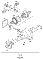
- the first axle housing type is a unitized carrier construction, commonly referred to as a Salisbury type axle assembly, illustrated in Fig. 1.
- the Salisbury type axle assembly 301 includes a carrier 312 (which houses a rotatable differential mechanism 340) is directly connected to the two tubes 316 and 317 (which house the rotatable axle shafts 320).
- An opening is provided at the rear of the carrier to permit assembly of the differential therein.
- a cover 326 closes this opening during the use.
- the cover 326 is connected by bolts (not shown) to a rear face 330 of the carrier 312 hydraulically seals the housing against the passage of lubricant.
- a brake assembly 314 located at the end of a tube 316 extending outboard from the ends of an axle carrier 312.
- a drive pinion 332 rotatably supported by a rear drive pinion bearing 334 and a front drive pinion bearing (not shown) supported on the inner surface of a portion of the axle carrier casing 338 that extends forward from the center line of the axle assembly.
- a driveshaft driveably connected to the output shaft of a transmission, is coupled to the shaft of the drive pinion 332.
- the differential mechanism 340 located within the differential case 348, includes a ring gear 342, in continuous meshing engagement with drive pinion 332 and supported rotatably on the differential rear drive pinion bearing 334 and the front drive pinion bearing located within the housing gear and cylindrical extension 338 of the carrier 312.
- the axle carrier 312 also includes laterally directed tubular extensions 344, 346, which receive therein the ends of housing tubes 316 and 317, respectively.
- a differential case 348 Located within the carrier 312 is a differential case 348, on which bevel pinion gears 350, 352 are supported for rotation on a differential pinion shaft 354.
- Side bevel gears 356, 358 are in continuous meshing engagement with pinions 350, 352 and are driveably connected to left and right axle shafts 320, located respectively within tubes 316 and 317.
- the axle shaft 320 is connected to the corresponding side bevel gear 356.
- Unitized carrier axle housing constructions of this type are economical to manufacture and are readily adaptable for a variety of vehicles.
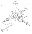
- the second axle housing type is a separable carrier construction, and is commonly referred to as a Banjo type axle, illustrated in Fig. 2.
- the Banjo type axle 401 includes an axle housing 402 having axle tubes 406a and 406b connected together by a central member 404.
- the axle tubes 406a and 406b are adapted to receive and rotatably support output axle shafts 414a and 414b.
- the axle housing 402 is formed separate and apart from a carrier 422.
- This central member 404 is generally hollow and cylindrical in shape, having a large generally circular opening 410 formed therethrough.
- this type of axle housing i.e., the generally round shape of the central member 404 and the elongated tubes 406a and 406b extending therefrom
- this type of axle housing is referred to as the Banjo type axle housing.
- the Banjo type axle housings are advantageous because the carrier 422 and differential 420 can be removed from the axle assembly 401 for service without disturbing the other components thereof.
- the present invention provides a novel rigid drive axle assembly for motor vehicles.
- the rigid drive axle assembly in accordance with the present invention comprises a support beam member having a substantially flat, enlarged central plate section and two opposite arm sections extending axially outwardly from the central plate section.
- the flat enlarged central section is further provided with a central opening therethrough.
- the drive axle assembly further comprises a differential assembly module fastened to the enlarged central plate section of the support beam member, and two opposite axle shaft members outwardly extending from the differential assembly module, and rotatably supported by the arm sections of the support beam member so that the axle shaft members are spaced from the central plate section of the support beam member in a driving direction of the motor vehicle. Distal ends of the axle shaft members are provided with flange members adapted for mounting corresponding wheel hubs.
- the differential assembly module is enclosed into a housing formed by a rear cover and a front cover secured to opposite surfaces of the central plate section of the beam member.
- the differential assembly module includes a differential carrier frame member fastened to the central plate section of the support beam member, and provided for rotatably supporting a differential case and a drive pinion.
- the differential case houses a conventional differential gear mechanism, well known to those skilled in the art.
- the drive pinion has a pinion gear in continuous meshing engagement with a ring gear, and a pinion shaft operatively coupled to a vehicular drive shaft driven by a vehicular powerplant through an input yoke.
- the differential assembly module is enclosed into a housing formed by a rear cover and a front cover secured to opposite surfaces of the central plate section of the beam member in any appropriate manner well known in the art.
- the front cover has a front opening for rotatably supporting and receiving therethrough a distal end of the pinion shaft of the drive pinion.
- the rear cover incorporates two opposite through holes for receiving the axle shaft members therethrough. Each of the through holes is provided with a self-centering seal.
- the differential carrier frame member is, preferably, a single-piece metal part manufactured by casting or forging.
- the differential carrier frame member has a generally Y-shaped configuration and includes a neck portion and two opposite, axially spaced, coaxial bearing hub portions attached to the neck portion through respective leg portions.
- the neck portion has an opening therethrough adapted for receiving and rotatably supporting the drive pinion through appropriate anti-friction bearings, preferably roller bearings.
- the bearing hub portions are provided with respective openings therethrough adapted for receiving appropriate anti-friction bearings for rotatably supporting the differential carrier.
- the bearing hub portions are provided with mounting flange portions.
- a method for assembling the drive axle assembly of the present invention comprises the steps of fastening the differential carrier frame member of the differential assembly module to a rear mounting surface of the support beam member so that the neck portion of the differential carrier frame member extends through the opening in the support beam member, placing the front cover of the drive axle assembly over the neck portion of the differential carrier frame member so that a distal end of a pinion shaft of the drive pinion of the differential assembly module extends through an opening in the front cover, securing the front cover to a front mounting surface of the axle support beam member, and fastening the rear cover to a rear mounting surface of the axle support beam member.
- the rigid drive axle assembly and the method for assembling it in accordance with the present invention represents a novel arrangement of the drive axle assembly and assembling technique providing a number of advantages over the currently employed Salisbury and Banjo style axles, such as improved strength to weight ratio, ease of manufacturing and reduced manufacturing cost due to the use of simple metal stampings to produce the support beam member and the front cover, ease of assembly/disassembly and servicing of the axle assembly, and improved modularity and commonality of axle components.
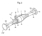
- Figs. 3-5 depict a vehicle rigid drive axle assembly 1 in accordance with the first exemplary embodiment of the present invention. It will be appreciated that the present invention is equally applicable to an independent drive axle assembly, and may be used for both front and rear axle applications.
- the rigid drive axle assembly 1 comprises a support beam member 2 having a substantially flat, enlarged central plate section 4 and two opposite, substantially tubular arm sections 6a and 6b axially outwardly extending from the central plate section 4.
- the flat central plate section 4 of the support beam member 2 is in the form of a substantially vertically oriented flat plate and defines a support plane that is substantially orthogonal to the driving direction F of the motor vehicle.
- the arm sections 6a and 6b are formed integrally with the central plate section 4.
- the opposite arm sections 6a and 6b of the support beam member 2 may be provided with spring seats 50a and 50b, respectively.
- the drive axle assembly 1 further comprises a differential assembly module 20 fastened to the enlarged central plate section 4 of the support beam member 2, and two opposite axle shaft members 14a and 14b outwardly extending from the differential assembly module 20, and rotatably supported by the arm sections 6a and 6b of the support beam member 2 so that the axle shaft members 14a and 14b are spaced from the central plate section 4 of the beam member 2 in the driving direction F of the motor vehicle.
- Distal ends of the axle shaft members 14a and 14b are provided with flange members 15a and 15b, respectively, adapted for mounting corresponding wheel hubs (not shown).
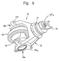
- the differential assembly module 20 shown in Figs. 4 and 8, includes a differential carrier frame member 22 fastened to the central plate section 4 of the beam member 2, and provided for rotatably supporting a differential case 34 and a drive pinion 38.
- the differential case 34 houses a differential gear mechanism, well known to those skilled in the art.
- the drive pinion 38 has a pinion gear 38a in continuous meshing engagement with a ring gear 36, and a pinion shaft 38b operatively coupled to a vehicular propeller shaft (not shown) driven by a vehicular powerplant (not shown), such as an internal combustion engine, through an input yoke 39.
- a mounting companion flange may be attached to a distal end of the pinion shaft 38b (instead of the input yoke 39) for coupling the pinion shaft 38b to the vehicular propeller shaft driven by the vehicular powerplant.
- the ring gear 36 is conventionally secured to the differential case 34 in any appropriate manner well known in the art.
- the differential assembly module 20 of the present invention is a self-contained unit wherein the differential carrier frame member 22 supports all the significant elements of the differential assembly and a final drive, such as the differential case 34 housing the differential gear mechanism, differential bearings 35a and 35b, threaded differential adjusters 32a and 32b, differential adjuster locks, oil seals, the drive pinion 38, drive pinion bearings, and the input yoke 39.
- the differential carrier frame member 22 fastened to the central plate section 4 of the support beam member 2 using conventional fasteners, such as bolts 21.
- the differential carrier frame member 22 of the present invention improves the modularity of design of the differential assembly, substantially simplifies the assembly and servicing of the differential assembly, and reduces the number of required machining operations.
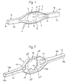
- Fig. 6 depicts in detail the support beam member 2 in accordance with the first exemplary embodiment of the present invention.
- the support beam member 2 has the substantially flat, enlarged central plate section 4 and the two opposite, substantially tubular arm sections 6a and 6b axially outwardly extending from the central plate section 4.
- the support beam member 2 is formed of a single-piece C-channel body 8 manufactured by a metal deforming, such as stamping, having a substantially flat, enlarged central plate section 8c and two opposite arm sections 8a and 8b axially outwardly extending from the central plate section 8c.
- the flat central plate section 8c of the body 8 is in the form of a substantially vertically oriented flat plate.
- the enlarged central plate section 8c of the body 8 defines the central plate section 4 of the support beam member 2.
- the enlarged central plate section 8c has substantially flat front and rear mounting surfaces 8 F and 8 R , respectively.
- the central plate section 8c is further provided with a central opening 10 therethrough adapted for receiving the differential carrier frame member 22 of the differential assembly module 20.
- the support beam member 2 further includes two structural plates 12a and 12b attached to the arm sections 8a and 8b, respectively, in any appropriate manner, such as welding, so as to form the substantially tubular arm sections 6a and 6b of the support beam member 2 housing the axle shaft members 14a and 14b.
- the tubular arm sections 6a and 6b of the support beam member 2 have substantially rectangular cross-section. Inward ends of each of the structural plates 12a and 12b is provided with a notch 16 receiving the axle shaft member 14a or 14b therethrough in a spaced relationship with respect to the central plate section 8c of the body 8 of the support beam member 2.
- the tubular arm sections 6a and 6b of the support beam member 2 have substantially circular cross-section, as illustrated in Fig. 7.
- a plurality of mounting holes 9 are formed in the central plate section 8c adjacent to the central opening 10.
- the mounting holes 9 are adapted to receive the bolts 21 for fastening the differential carrier frame member 22 to the rear mounting surface 8 R of the central plate section 8c of the body 8 of the support beam member 2.
- the mounting holes 9 are smooth, and the plurality of bolts 21 with complementary nuts (not shown) are provided in order to fasten the differential carrier frame member 22 to the flat central plate section 4 of the support beam member 2.
- each of the mounting holes 9 is provided with a weld-on nut adapted to threadedly engage the complementary bolts 21.
- the differential carrier frame member 22 is fastened to the flat central plate section 4 of the support beam member 2 using a plurality of threaded studs (not shown) fixed to the rear mounting surface 8 R of the central plate section 8c, in combination with complementary threaded nuts (not shown).
- the threaded studs extend substantially orthogonally to the rear mounting surface 8 R of the central plate section 8c.
- the differential assembly module 20 is enclosed into a housing formed by a rear cover 40 and a front cover 46 secured to opposite surfaces of the central plate section 4 of the beam member 2 in any appropriate manner well known in the art.
- both the rear cover 40 and the front cover 46 are manufactured by metal stamping of any appropriate metal material, such as steel.
- the rear cover 40 could be made of any appropriate material, such as composite material (e.g. glass filled nylon).
- the front cover 46 is welded to a front surface of the central plate section 4 of the beam member 2, while the rear cover 40 is fastened to a rear surface of the central plate section 4 of the beam member 2 using conventional fasteners 41.
- the front cover 46 has a front opening 48 (shown in Figs. 4 and 5) for receiving therethrough a distal end of the pinion shaft 38b of the drive pinion 38.
- the front opening 48 is formed by a front flange collar 49a provided with a plurality of through holes 49' spaced apart substantially circumferentially, equidistantly around the front opening 48.
- the front cover 46 is further provided with a rear flange 49b adapted to juxtapose the front mounting surface 8 F of the enlarged central plate section 8c of the single-piece C-channel body 8.
- the rear cover 40 incorporates two opposite through holes 42 (only one is shown in Fig. 4) for receiving the axle shaft members 14a and 14b therethrough.
- Each of the through holes 42 is provided with an adjustable flange device 44 provided with an axle shaft seal 44' adapted to seal the through hole 42 about the axle shaft members 14a and 14b.
- the adjustable flange device 44 is secured to the rear cover 40 adjacent to the through hole 42 therein by a set of screws 45 and is adapted to adjust a position of the axle shaft seal 44' relative to the through hole 42 of the rear cover 40.
- the rear cover 40 is further provided with a mounting flange 43 adapted to juxtapose the rear mounting surface 8 R of the enlarged central plate section 8c of the single-piece C-channel body 8.
- the mounting flange 43 of the rear cover 40 is provided with a plurality of spaced apart through holes 43'.
- the support beam member 2 further includes a plurality of smaller mounting holes 11 formed in the central plate section 8c of the body 8 adjacent to the central opening 10 for receiving the screws 41 adapted to fasten the rear cover 40 to the central plate section 4 of the support beam member 2.
- the mounting holes 11 are provided with threads complementary to threads of the screws 41.
- the mounting holes 11 may be smooth, and a plurality of bolts with complementary nuts (not shown) are provided in order to fasten the rear cover 40 to the flat central plate section 4 of the support beam member 2. It will be appreciated that any appropriate manner of securing the rear cover 40 to the rear mounting surface 8 R of the central plate section 8c of the body 8 of the support beam member 2 is within the scope of the present invention.
- the differential carrier frame member 22 illustrated in detail in Fig. 9, is, preferably, a single-piece metal part manufactured by casting or forging.
- the differential carrier frame member 22 has a generally Y-shaped configuration and includes a neck portion 24 and two opposite, axially spaced, coaxial bearing hub portions 26a and 26b attached to the neck portion 24 through respective leg portions 28a and 28b.
- the neck portion 24 has an opening 25 therethrough adapted for receiving and rotatably supporting the drive pinion 38 through an appropriate anti-friction bearing (not shown), preferably a tapered roller bearing.
- the bearing hub portions 26a and 26b are provided with respective openings 27a and 27b therethrough adapted for receiving appropriate anti-friction bearings 35a and 35b for rotatably supporting the differential case 34.
- the anti-friction bearings 35a and 35b are tapered roller bearings.
- the bearing hub portions 26a and 26b are provided with mounting flange portions 30a and 30b respectively, for fastening the differential carrier frame member 22 to the rear mounting surface 8 R of the flat central plate section 4 of the support beam member 2.
- each of the mounting flange portions 30a and 30b has two mounting holes 31a and 31b, respectively, adapted to receive the screws 21.
- the screws 21 extend through the mounting holes 31a and 31b in the differential carrier frame member 22 and threaded into the mounting holes 9 formed in the central plate section 8c of the body 8, thus fastening the differential carrier frame member 22 of the differential assembly module 20 to the central plate section 4 of the beam member 2.
- a geometric location of the mounting holes 9 in the central plate section 8c of the body 8 is substantially complementary to location the mounting holes 3 1 a and 31b of the mounting flange portions 30a and 30b of the differential carrier frame member 22.
- the bolts 21 extend through the mounting holes 31a and 31b in the differential carrier frame member 22 and the mounting holes 9 to extend through the central plate section 8c of the body 8, and are threaded with the complementary nuts (or weld-on nuts) on the opposite side of the central plate section 8c, thus fastening the differential carrier frame member 22 to the central plate section 4 of the beam member 2.
- the differential carrier frame member 22 is mounted to the central plate section 4 of the beam member 2 by the threaded studs extending through the mounting holes 31a and 31b in the differential carrier frame member 22, and fastened to the central plate section 4 of the beam member 2 with the complementary nuts.
- a geometric location of the threaded studs is substantially complementary to location the mounting holes 31a and 31b of the mounting flange portions 30a and 30b of the differential carrier frame member 22.
- the neck portion 24 of the differential carrier frame member 22 has a substantially annular flange member 52 provided with a plurality of holes 54 spaced apart substantially circumferentially, equidistantly around the flange member 52.
- the holes 54 are threaded. It will be appreciated that a geometric location of the through holes 54 is substantially complementary to location the through holes 49' of the front flange collar 49a of the front cover 46.
- the preferred embodiment of a method of assembling the rigid drive axle assembly 1 in accordance with the present invention is performed in the following manner.
- the front cover 46 is secured to the central plate section 8c of the C-channel body 8 of the support beam member 2 by welding the rear flange 49b of the front cover 46 to the front mounting surface 8 F of the central plate section 8c. It will be appreciated that any other techniques of securing the front cover 46 to the front mounting surface 8 F , such as adhesive bonding, bolting, riveting, etc., is within the scope of the present invention.
- the differential assembly module 20 is assembled by mounting and securing the differential case 34 housing a differential gear mechanism and the drive pinion 38 to the differential carrier frame member 22.
- the input yoke 39 is attached to the distal end of the pinion shaft 38b by any appropriate means well known in the art, such as spline connection, and secured by a threaded nut 39a.
- the differential bearings 35a and 35b are preloaded by the differential adjusters 32a and 32b. Differential bearings supporting the drive pinion 38 are also preloaded.
- the fully assembled and preloaded differential assembly module 20 is mounted to the support beam member 2 by fastening the differential carrier frame member 22 to the rear mounting surface 8 R of the support beam member 2 so that the neck portion 24 of the differential carrier frame member 22 extends trough the opening 10 in the central plate section 4 of the support beam member 2 and the distal end of the pinion shaft 38b of the drive pinion 38 of the differential assembly module 20 extends through the opening 48 in the front cover 46.
- the front flange collar 49a of the front cover 46 is juxtaposed to the annular flange member 52 of the neck portion 24 of the differential carrier frame member 22.
- the mounting flange portions 30a and 30b of the differential carrier frame member 22 are fastened to the rear mounting surface 8 R of the enlarged, central plate section 8c of the C-channel body 8 of the support beam member 2 by threading of the bolts 21 inserted into the mounting holes 31a and 31b in the differential carrier frame member 22 and the mounting holes 9 to extend through the central plate section 8c of the body 8, and are threaded with the complementary nuts on the opposite side of the central plate section 8c, thus fastening the differential carrier frame member 22 to the central plate section 4 of the beam member 2.
- the differential carrier frame member 22 is mounted to the central plate section 4 of the beam member 2 by the threaded studs extending through the mounting holes 31 a and 31b in the differential carrier frame member 22, and fastened to the central plate section 4 of the beam member 2 with the complementary nuts.
- the front flange collar 49a of the front cover 46 is fastened to the annular flange member 52 of the neck portion 24 of the differential carrier frame member 22 by a plurality of screws 47 extending through the through holes 49' of the front flange collar 49a of the front cover 46 and threaded into the threaded holes 54 in the annular flange member 52 of the neck portion 24 of the differential carrier frame member 22.
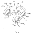
- the rear cover 40 is fastened to the axle support beam member 2 to cover a rear part of the differential assembly module 20 extending in a rearward direction from the central plate section 4 of the support beam member 2. More specifically, the rear cover 40 is placed over the rear part of the differential assembly module 20 so that the mounting flange 43 of the rear cover 40 is juxtaposed to the rear mounting surface 8 R of the central plate section 8c of the C-channel body 8 of the support beam member 2.
- the rear cover 40 is fastened to the rear mounting surface 8 R of the central plate section 8c of the body 8 by the plurality of the screws 41 extending through the corresponding through holes 43' in the mounting flange 43 of the rear cover 40 and threaded into the mounting holes 11 in the central plate section 8c of the body 8.
- axle shaft members 14a and 14b inserted into the arm sections 6a and 6b of the support beam member 2 in an inward direction through the holes 42 in the rear cover 40 into a positive engagement with side gears of the differential gear mechanism of the differential assembly module 20 within the differential case 34.
- front cover 46 may secured to the central plate section 8c of the body 8 of the support beam member 2 after the differential assembly module 20 is fastened to the support beam member 2.
- the axle assembly in accordance with the present invention represents a novel method for assembling the drive axle assembly of a motor vehicle including the support beam member having the substantially flat central plate section and two opposite arm sections axially outwardly extending from the central plate section, the differential assembly module secured to the flat central plate section of the support beam member, and two opposite axle shaft members outwardly extending from the differential assembly module and rotatably supported by the arm sections in a spaced relationship with respect to the central plate section of the support beam member.
Landscapes
- Engineering & Computer Science (AREA)
- Mechanical Engineering (AREA)
- General Engineering & Computer Science (AREA)
- Chemical & Material Sciences (AREA)
- Combustion & Propulsion (AREA)
- Transportation (AREA)
- Retarders (AREA)
- Motor Power Transmission Devices (AREA)
- Arrangement Or Mounting Of Propulsion Units For Vehicles (AREA)
- Electric Propulsion And Braking For Vehicles (AREA)
- General Details Of Gearings (AREA)
Applications Claiming Priority (2)
| Application Number | Priority Date | Filing Date | Title |
|---|---|---|---|
| US10/695,877 US7137183B2 (en) | 2002-03-20 | 2003-10-30 | Drive axle for motor vehicles and method for assembling the same |
| US695877 | 2003-10-30 |
Publications (1)
| Publication Number | Publication Date |
|---|---|
| EP1527936A1 true EP1527936A1 (fr) | 2005-05-04 |
Family
ID=34423358
Family Applications (1)
| Application Number | Title | Priority Date | Filing Date |
|---|---|---|---|
| EP04105402A Withdrawn EP1527936A1 (fr) | 2003-10-30 | 2004-10-29 | Essieu d'entraínement pour véhicule automobile et procédé de sa fabrication |
Country Status (5)
| Country | Link |
|---|---|
| US (1) | US7137183B2 (fr) |
| EP (1) | EP1527936A1 (fr) |
| CN (1) | CN1644413A (fr) |
| AU (1) | AU2004224969A1 (fr) |
| BR (1) | BRPI0406068A (fr) |
Cited By (3)
| Publication number | Priority date | Publication date | Assignee | Title |
|---|---|---|---|---|
| WO2016207635A1 (fr) * | 2015-06-23 | 2016-12-29 | Ricardo Uk Ltd. | Ensemble d'engrenages de différentiel et procédé d'assemblage |
| WO2018104760A1 (fr) * | 2016-12-07 | 2018-06-14 | Volvo Truck Corporation | Ensemble destiné à une unité différentielle d'un véhicule |
| CN117359286A (zh) * | 2023-10-26 | 2024-01-09 | 池州莫新机电科技有限公司 | 汽车后桥壳体与差速器自动装配生产线 |
Families Citing this family (17)
| Publication number | Priority date | Publication date | Assignee | Title |
|---|---|---|---|---|
| CA2574615A1 (fr) * | 2004-07-27 | 2006-02-02 | Hino Motors, Ltd. | Procede de montage d'un module d'essieu |
| US20080121070A1 (en) * | 2006-08-28 | 2008-05-29 | Krisher James A | Axle and axle components and method of manufacturing |
| US8776374B2 (en) | 2010-04-30 | 2014-07-15 | Trimtool Ltd. O/A 1823912 Ontario Inc. | Method and apparatus for manufacturing an axle for a vehicle |
| DE102010043596A1 (de) * | 2010-11-09 | 2012-05-24 | Zf Friedrichshafen Ag | Lageranordnung |
| CN102910034A (zh) * | 2012-11-20 | 2013-02-06 | 中国重汽集团济南动力有限公司 | 一种重型汽车独立悬挂驱动桥壳总成 |
| US9109689B2 (en) * | 2013-02-27 | 2015-08-18 | American Axle & Manufacturing, Inc. | Axle assembly having banjo beam and strengthened coverpan |
| US9517658B2 (en) * | 2014-07-11 | 2016-12-13 | American Axle & Manufacturing, Inc. | Axle assembly with carrier housing having increased strength and reduced mass |
| CN104290537B (zh) * | 2014-10-28 | 2016-04-27 | 重庆长安汽车股份有限公司 | 一种后驱动桥桥壳总成 |
| US9919559B2 (en) * | 2014-12-11 | 2018-03-20 | Ford Global Technologies, Llc | Axle carrier housing with a swept support rib |
| JP6754630B2 (ja) * | 2016-06-27 | 2020-09-16 | 株式会社クボタ | 車軸装置 |
| GB2554450B (en) * | 2016-09-29 | 2020-01-15 | Jaguar Land Rover Ltd | A drive assembly for a vehicle |
| GB2557985A (en) * | 2016-12-21 | 2018-07-04 | Ricardo Uk Ltd | Differential gear assembly and method of assembly |
| CN111801235B (zh) * | 2018-03-09 | 2023-09-29 | 丰田自动车株式会社 | 轮轴结构 |
| US11535057B2 (en) | 2020-09-09 | 2022-12-27 | Mahindra N.A. Tech Center | Axle assembly with sealed wheel end bearings and sealed pinion input bearings |
| US11225107B1 (en) | 2020-09-09 | 2022-01-18 | Mahindra N.A. Tech Center | Axle carrier housing with reinforcement structure |
| US11655891B2 (en) | 2020-09-09 | 2023-05-23 | Mahindra N.A. Tech Center | Method of machining an axle carrier housing |
| US11648745B2 (en) | 2020-09-09 | 2023-05-16 | Mahindra N.A. Tech Center | Modular tooling for axle housing and manufacturing process |
Citations (6)
| Publication number | Priority date | Publication date | Assignee | Title |
|---|---|---|---|---|
| US2612231A (en) * | 1947-06-28 | 1952-09-30 | Bretschneider Curt | Individually swingable driven axle |
| US3170534A (en) * | 1959-01-07 | 1965-02-23 | Gen Motors Corp | Transmission and swinging drive axles including torque converters |
| US4594912A (en) * | 1979-07-19 | 1986-06-17 | Toyota Jidosha Kogyo Kabushiki Kaisha | Banjo type axle casing |
| US5188195A (en) * | 1991-11-12 | 1993-02-23 | Haustein Norman E | Vehicle driving wheel suspension system |
| GB2295588A (en) * | 1994-11-30 | 1996-06-05 | Gkn Technology Ltd | Vehicle suspension and drive arrangement |
| WO2003080366A2 (fr) * | 2002-03-20 | 2003-10-02 | Dana Corporation | Ensemble essieu moteur modulaire pour vehicules a moteur |
Family Cites Families (9)
| Publication number | Priority date | Publication date | Assignee | Title |
|---|---|---|---|---|
| US899891A (en) | 1906-04-18 | 1908-09-29 | Jules Niclausse | Axle for motor road-vehicles. |
| US1002858A (en) | 1909-08-19 | 1911-09-12 | Charles T Mccue | Gearing. |
| US1076559A (en) | 1912-06-05 | 1913-10-21 | Ellsworth & Cross | Axle for motor-vehicles. |
| US1076500A (en) | 1912-07-13 | 1913-10-21 | J A John Ag | Roof-light. |
| US1386510A (en) | 1920-04-29 | 1921-08-02 | Allen R Cosgrove | Rear-axle structure for motor-vehicles |
| US3792625A (en) | 1971-06-28 | 1974-02-19 | Skf Ind Trading & Dev | Pinion gear transmission |
| US4841802A (en) * | 1986-03-27 | 1989-06-27 | Rockwell International Corporation | Modified fast fade drive axle housing |
| US5271294A (en) * | 1992-05-08 | 1993-12-21 | Dana Corporation | Banjo type axle housing having differential carrier support structure |
| US5297855A (en) * | 1992-07-16 | 1994-03-29 | Dana Corporation | Banjo-type axle housing |
-
2003
- 2003-10-30 US US10/695,877 patent/US7137183B2/en not_active Expired - Fee Related
-
2004
- 2004-10-29 BR BR0406068-7A patent/BRPI0406068A/pt not_active Application Discontinuation
- 2004-10-29 EP EP04105402A patent/EP1527936A1/fr not_active Withdrawn
- 2004-11-01 CN CNA2004101037461A patent/CN1644413A/zh active Pending
- 2004-11-01 AU AU2004224969A patent/AU2004224969A1/en not_active Abandoned
Patent Citations (6)
| Publication number | Priority date | Publication date | Assignee | Title |
|---|---|---|---|---|
| US2612231A (en) * | 1947-06-28 | 1952-09-30 | Bretschneider Curt | Individually swingable driven axle |
| US3170534A (en) * | 1959-01-07 | 1965-02-23 | Gen Motors Corp | Transmission and swinging drive axles including torque converters |
| US4594912A (en) * | 1979-07-19 | 1986-06-17 | Toyota Jidosha Kogyo Kabushiki Kaisha | Banjo type axle casing |
| US5188195A (en) * | 1991-11-12 | 1993-02-23 | Haustein Norman E | Vehicle driving wheel suspension system |
| GB2295588A (en) * | 1994-11-30 | 1996-06-05 | Gkn Technology Ltd | Vehicle suspension and drive arrangement |
| WO2003080366A2 (fr) * | 2002-03-20 | 2003-10-02 | Dana Corporation | Ensemble essieu moteur modulaire pour vehicules a moteur |
Cited By (6)
| Publication number | Priority date | Publication date | Assignee | Title |
|---|---|---|---|---|
| WO2016207635A1 (fr) * | 2015-06-23 | 2016-12-29 | Ricardo Uk Ltd. | Ensemble d'engrenages de différentiel et procédé d'assemblage |
| WO2016207634A1 (fr) * | 2015-06-23 | 2016-12-29 | Ricardo Uk Ltd. | Différentiel |
| WO2018104760A1 (fr) * | 2016-12-07 | 2018-06-14 | Volvo Truck Corporation | Ensemble destiné à une unité différentielle d'un véhicule |
| US10974594B2 (en) | 2016-12-07 | 2021-04-13 | Volvo Truck Corporation | Assembly for a differential unit of a vehicle |
| CN117359286A (zh) * | 2023-10-26 | 2024-01-09 | 池州莫新机电科技有限公司 | 汽车后桥壳体与差速器自动装配生产线 |
| CN117359286B (zh) * | 2023-10-26 | 2024-04-02 | 池州莫新机电科技有限公司 | 汽车后桥壳体与差速器自动装配生产线 |
Also Published As
| Publication number | Publication date |
|---|---|
| US20050091823A1 (en) | 2005-05-05 |
| CN1644413A (zh) | 2005-07-27 |
| BRPI0406068A (pt) | 2005-06-28 |
| AU2004224969A1 (en) | 2005-05-19 |
| US7137183B2 (en) | 2006-11-21 |
Similar Documents
| Publication | Publication Date | Title |
|---|---|---|
| US7137183B2 (en) | Drive axle for motor vehicles and method for assembling the same | |
| US7410440B2 (en) | Method for converting a non-driven tag axle system to a driven axle system | |
| EP0572822B1 (fr) | Montage d'essieu moteur monté en tandem et sous-assemblage de pignon y destiné | |
| EP1586794A2 (fr) | Différentiel avec paliers de pignon supporté de la mâchoire d'entrante | |
| US6729207B2 (en) | Rigid drive axle assembly for motor vehicles | |
| EP3144561B1 (fr) | Ensemble d'essieu de bogie | |
| US20110152028A1 (en) | Four pinion differential with cross pin retention unit and related method | |
| CN108136891B (zh) | 轮内电动机驱动装置 | |
| US10889178B2 (en) | In-wheel motor drive device | |
| US7155827B2 (en) | Method for verifying predetermined bearing preload of differential assembly module | |
| US7121972B2 (en) | Adjustable flange device for cover member in drive axle assembly | |
| US20030083171A1 (en) | Differential with pinion bearings supported on input yoke | |
| US20070049452A1 (en) | Common center section for independent rear suspension and fixed axle applications | |
| US7258644B2 (en) | Tandem axle carrier structural rib | |
| US20080121070A1 (en) | Axle and axle components and method of manufacturing | |
| US7059215B1 (en) | Rear assembly tandem axle differential carrier | |
| US20060000308A1 (en) | Axle assembly with opposed electric motor carrier | |
| AU2003223292A1 (en) | Modular drive axle assembly for motor vehicles | |
| US20050026734A1 (en) | Tandem axle pinion shaft subassembly | |
| US20230023967A1 (en) | Differential Housing | |
| CN111946795A (zh) | 具有悬伸环形齿轮的差速器组件 | |
| US20210108712A1 (en) | Vehicle drivetrain differential assembly | |
| JP2005225255A (ja) | 駆動軸の支持構造 | |
| KR20040006864A (ko) | 볼트 고정형 액슬 케이싱 |
Legal Events
| Date | Code | Title | Description |
|---|---|---|---|
| PUAI | Public reference made under article 153(3) epc to a published international application that has entered the european phase |
Free format text: ORIGINAL CODE: 0009012 |
|
| AK | Designated contracting states |
Kind code of ref document: A1 Designated state(s): AT BE BG CH CY CZ DE DK EE ES FI FR GB GR HU IE IT LI LU MC NL PL PT RO SE SI SK TR |
|
| AX | Request for extension of the european patent |
Extension state: AL HR LT LV MK |
|
| AKX | Designation fees paid | ||
| REG | Reference to a national code |
Ref country code: DE Ref legal event code: 8566 |
|
| STAA | Information on the status of an ep patent application or granted ep patent |
Free format text: STATUS: THE APPLICATION IS DEEMED TO BE WITHDRAWN |
|
| 18D | Application deemed to be withdrawn |
Effective date: 20051105 |