EP1527839B1 - Abschmelzschweissverfahren und der daraus resultierende Artikel - Google Patents
Abschmelzschweissverfahren und der daraus resultierende Artikel Download PDFInfo
- Publication number
- EP1527839B1 EP1527839B1 EP04256647A EP04256647A EP1527839B1 EP 1527839 B1 EP1527839 B1 EP 1527839B1 EP 04256647 A EP04256647 A EP 04256647A EP 04256647 A EP04256647 A EP 04256647A EP 1527839 B1 EP1527839 B1 EP 1527839B1
- Authority
- EP
- European Patent Office
- Prior art keywords
- interface
- weld
- interface surface
- fusion
- interface surfaces
- Prior art date
- Legal status (The legal status is an assumption and is not a legal conclusion. Google has not performed a legal analysis and makes no representation as to the accuracy of the status listed.)
- Expired - Lifetime
Links
- 238000000034 method Methods 0.000 title claims description 33
- 238000003466 welding Methods 0.000 title claims description 32
- 230000004927 fusion Effects 0.000 title claims description 23
- 239000010410 layer Substances 0.000 claims description 29
- 229910000765 intermetallic Inorganic materials 0.000 claims description 27
- 229910052751 metal Inorganic materials 0.000 claims description 27
- 239000002184 metal Substances 0.000 claims description 27
- 229910000601 superalloy Inorganic materials 0.000 claims description 21
- 230000015572 biosynthetic process Effects 0.000 claims description 19
- PXHVJJICTQNCMI-UHFFFAOYSA-N Nickel Chemical compound [Ni] PXHVJJICTQNCMI-UHFFFAOYSA-N 0.000 claims description 17
- 229910052697 platinum Inorganic materials 0.000 claims description 12
- 239000011229 interlayer Substances 0.000 claims description 11
- 229910052782 aluminium Inorganic materials 0.000 claims description 8
- 229910052707 ruthenium Inorganic materials 0.000 claims description 8
- 229910052763 palladium Inorganic materials 0.000 claims description 7
- 229910052703 rhodium Inorganic materials 0.000 claims description 7
- 239000004411 aluminium Substances 0.000 claims description 6
- XAGFODPZIPBFFR-UHFFFAOYSA-N aluminium Chemical compound [Al] XAGFODPZIPBFFR-UHFFFAOYSA-N 0.000 claims description 6
- 238000009527 percussion Methods 0.000 claims description 5
- 238000010891 electric arc Methods 0.000 claims description 3
- 229910052759 nickel Inorganic materials 0.000 claims description 2
- 229910045601 alloy Inorganic materials 0.000 description 34
- 239000000956 alloy Substances 0.000 description 34
- BASFCYQUMIYNBI-UHFFFAOYSA-N platinum Substances [Pt] BASFCYQUMIYNBI-UHFFFAOYSA-N 0.000 description 14
- 238000005336 cracking Methods 0.000 description 8
- 238000010438 heat treatment Methods 0.000 description 8
- 150000002739 metals Chemical class 0.000 description 8
- 238000005304 joining Methods 0.000 description 7
- 230000008439 repair process Effects 0.000 description 7
- 150000001875 compounds Chemical class 0.000 description 6
- 238000001816 cooling Methods 0.000 description 6
- 239000000463 material Substances 0.000 description 6
- 229910000510 noble metal Inorganic materials 0.000 description 5
- 238000005728 strengthening Methods 0.000 description 4
- 239000003990 capacitor Substances 0.000 description 3
- 238000005266 casting Methods 0.000 description 3
- 230000001627 detrimental effect Effects 0.000 description 3
- 230000007613 environmental effect Effects 0.000 description 3
- 238000001556 precipitation Methods 0.000 description 3
- 229910000951 Aluminide Inorganic materials 0.000 description 2
- 239000011248 coating agent Substances 0.000 description 2
- 238000000576 coating method Methods 0.000 description 2
- 238000002485 combustion reaction Methods 0.000 description 2
- 230000002708 enhancing effect Effects 0.000 description 2
- 230000003993 interaction Effects 0.000 description 2
- 238000004519 manufacturing process Methods 0.000 description 2
- 238000002844 melting Methods 0.000 description 2
- 230000008018 melting Effects 0.000 description 2
- 230000003647 oxidation Effects 0.000 description 2
- 238000007254 oxidation reaction Methods 0.000 description 2
- 230000000704 physical effect Effects 0.000 description 2
- 239000002244 precipitate Substances 0.000 description 2
- 239000000047 product Substances 0.000 description 2
- 239000007787 solid Substances 0.000 description 2
- 229910018525 Al—Pt Inorganic materials 0.000 description 1
- 229910001252 Pd alloy Inorganic materials 0.000 description 1
- KJTLSVCANCCWHF-UHFFFAOYSA-N Ruthenium Chemical compound [Ru] KJTLSVCANCCWHF-UHFFFAOYSA-N 0.000 description 1
- 238000005275 alloying Methods 0.000 description 1
- 230000004888 barrier function Effects 0.000 description 1
- 239000010953 base metal Substances 0.000 description 1
- 230000015556 catabolic process Effects 0.000 description 1
- 230000008859 change Effects 0.000 description 1
- 239000000356 contaminant Substances 0.000 description 1
- 238000006731 degradation reaction Methods 0.000 description 1
- 230000001419 dependent effect Effects 0.000 description 1
- 238000013461 design Methods 0.000 description 1
- 238000010894 electron beam technology Methods 0.000 description 1
- 238000011156 evaluation Methods 0.000 description 1
- 239000012530 fluid Substances 0.000 description 1
- -1 for example Substances 0.000 description 1
- 238000000227 grinding Methods 0.000 description 1
- 229910001063 inconels 617 Inorganic materials 0.000 description 1
- 229910052742 iron Inorganic materials 0.000 description 1
- 238000003754 machining Methods 0.000 description 1
- 229910001092 metal group alloy Inorganic materials 0.000 description 1
- 238000004377 microelectronic Methods 0.000 description 1
- 230000005012 migration Effects 0.000 description 1
- 238000013508 migration Methods 0.000 description 1
- 238000010587 phase diagram Methods 0.000 description 1
- 230000036316 preload Effects 0.000 description 1
- 238000012552 review Methods 0.000 description 1
- 239000006104 solid solution Substances 0.000 description 1
- 238000007711 solidification Methods 0.000 description 1
- 230000008023 solidification Effects 0.000 description 1
- 239000000758 substrate Substances 0.000 description 1
- 238000005486 sulfidation Methods 0.000 description 1
- 229910052723 transition metal Inorganic materials 0.000 description 1
- 150000003624 transition metals Chemical class 0.000 description 1
Images



Classifications
-
- B—PERFORMING OPERATIONS; TRANSPORTING
- B23—MACHINE TOOLS; METAL-WORKING NOT OTHERWISE PROVIDED FOR
- B23K—SOLDERING OR UNSOLDERING; WELDING; CLADDING OR PLATING BY SOLDERING OR WELDING; CUTTING BY APPLYING HEAT LOCALLY, e.g. FLAME CUTTING; WORKING BY LASER BEAM
- B23K11/00—Resistance welding; Severing by resistance heating
- B23K11/10—Spot welding; Stitch welding
- B23K11/11—Spot welding
- B23K11/115—Spot welding by means of two electrodes placed opposite one another on both sides of the welded parts
-
- B—PERFORMING OPERATIONS; TRANSPORTING
- B23—MACHINE TOOLS; METAL-WORKING NOT OTHERWISE PROVIDED FOR
- B23K—SOLDERING OR UNSOLDERING; WELDING; CLADDING OR PLATING BY SOLDERING OR WELDING; CUTTING BY APPLYING HEAT LOCALLY, e.g. FLAME CUTTING; WORKING BY LASER BEAM
- B23K2101/00—Articles made by soldering, welding or cutting
- B23K2101/001—Turbines
-
- Y—GENERAL TAGGING OF NEW TECHNOLOGICAL DEVELOPMENTS; GENERAL TAGGING OF CROSS-SECTIONAL TECHNOLOGIES SPANNING OVER SEVERAL SECTIONS OF THE IPC; TECHNICAL SUBJECTS COVERED BY FORMER USPC CROSS-REFERENCE ART COLLECTIONS [XRACs] AND DIGESTS
- Y10—TECHNICAL SUBJECTS COVERED BY FORMER USPC
- Y10S—TECHNICAL SUBJECTS COVERED BY FORMER USPC CROSS-REFERENCE ART COLLECTIONS [XRACs] AND DIGESTS
- Y10S428/00—Stock material or miscellaneous articles
- Y10S428/922—Static electricity metal bleed-off metallic stock
- Y10S428/923—Physical dimension
- Y10S428/924—Composite
- Y10S428/926—Thickness of individual layer specified
-
- Y—GENERAL TAGGING OF NEW TECHNOLOGICAL DEVELOPMENTS; GENERAL TAGGING OF CROSS-SECTIONAL TECHNOLOGIES SPANNING OVER SEVERAL SECTIONS OF THE IPC; TECHNICAL SUBJECTS COVERED BY FORMER USPC CROSS-REFERENCE ART COLLECTIONS [XRACs] AND DIGESTS
- Y10—TECHNICAL SUBJECTS COVERED BY FORMER USPC
- Y10S—TECHNICAL SUBJECTS COVERED BY FORMER USPC CROSS-REFERENCE ART COLLECTIONS [XRACs] AND DIGESTS
- Y10S428/00—Stock material or miscellaneous articles
- Y10S428/922—Static electricity metal bleed-off metallic stock
- Y10S428/9335—Product by special process
- Y10S428/934—Electrical process
-
- Y—GENERAL TAGGING OF NEW TECHNOLOGICAL DEVELOPMENTS; GENERAL TAGGING OF CROSS-SECTIONAL TECHNOLOGIES SPANNING OVER SEVERAL SECTIONS OF THE IPC; TECHNICAL SUBJECTS COVERED BY FORMER USPC CROSS-REFERENCE ART COLLECTIONS [XRACs] AND DIGESTS
- Y10—TECHNICAL SUBJECTS COVERED BY FORMER USPC
- Y10T—TECHNICAL SUBJECTS COVERED BY FORMER US CLASSIFICATION
- Y10T29/00—Metal working
- Y10T29/49—Method of mechanical manufacture
- Y10T29/49316—Impeller making
- Y10T29/49318—Repairing or disassembling
-
- Y—GENERAL TAGGING OF NEW TECHNOLOGICAL DEVELOPMENTS; GENERAL TAGGING OF CROSS-SECTIONAL TECHNOLOGIES SPANNING OVER SEVERAL SECTIONS OF THE IPC; TECHNICAL SUBJECTS COVERED BY FORMER USPC CROSS-REFERENCE ART COLLECTIONS [XRACs] AND DIGESTS
- Y10—TECHNICAL SUBJECTS COVERED BY FORMER USPC
- Y10T—TECHNICAL SUBJECTS COVERED BY FORMER US CLASSIFICATION
- Y10T428/00—Stock material or miscellaneous articles
- Y10T428/12—All metal or with adjacent metals
- Y10T428/12493—Composite; i.e., plural, adjacent, spatially distinct metal components [e.g., layers, joint, etc.]
- Y10T428/12771—Transition metal-base component
- Y10T428/12806—Refractory [Group IVB, VB, or VIB] metal-base component
-
- Y—GENERAL TAGGING OF NEW TECHNOLOGICAL DEVELOPMENTS; GENERAL TAGGING OF CROSS-SECTIONAL TECHNOLOGIES SPANNING OVER SEVERAL SECTIONS OF THE IPC; TECHNICAL SUBJECTS COVERED BY FORMER USPC CROSS-REFERENCE ART COLLECTIONS [XRACs] AND DIGESTS
- Y10—TECHNICAL SUBJECTS COVERED BY FORMER USPC
- Y10T—TECHNICAL SUBJECTS COVERED BY FORMER US CLASSIFICATION
- Y10T428/00—Stock material or miscellaneous articles
- Y10T428/12—All metal or with adjacent metals
- Y10T428/12493—Composite; i.e., plural, adjacent, spatially distinct metal components [e.g., layers, joint, etc.]
- Y10T428/12771—Transition metal-base component
- Y10T428/12806—Refractory [Group IVB, VB, or VIB] metal-base component
- Y10T428/12826—Group VIB metal-base component
- Y10T428/12847—Cr-base component
-
- Y—GENERAL TAGGING OF NEW TECHNOLOGICAL DEVELOPMENTS; GENERAL TAGGING OF CROSS-SECTIONAL TECHNOLOGIES SPANNING OVER SEVERAL SECTIONS OF THE IPC; TECHNICAL SUBJECTS COVERED BY FORMER USPC CROSS-REFERENCE ART COLLECTIONS [XRACs] AND DIGESTS
- Y10—TECHNICAL SUBJECTS COVERED BY FORMER USPC
- Y10T—TECHNICAL SUBJECTS COVERED BY FORMER US CLASSIFICATION
- Y10T428/00—Stock material or miscellaneous articles
- Y10T428/12—All metal or with adjacent metals
- Y10T428/12493—Composite; i.e., plural, adjacent, spatially distinct metal components [e.g., layers, joint, etc.]
- Y10T428/12771—Transition metal-base component
- Y10T428/12806—Refractory [Group IVB, VB, or VIB] metal-base component
- Y10T428/12826—Group VIB metal-base component
- Y10T428/12847—Cr-base component
- Y10T428/12854—Next to Co-, Fe-, or Ni-base component
-
- Y—GENERAL TAGGING OF NEW TECHNOLOGICAL DEVELOPMENTS; GENERAL TAGGING OF CROSS-SECTIONAL TECHNOLOGIES SPANNING OVER SEVERAL SECTIONS OF THE IPC; TECHNICAL SUBJECTS COVERED BY FORMER USPC CROSS-REFERENCE ART COLLECTIONS [XRACs] AND DIGESTS
- Y10—TECHNICAL SUBJECTS COVERED BY FORMER USPC
- Y10T—TECHNICAL SUBJECTS COVERED BY FORMER US CLASSIFICATION
- Y10T428/00—Stock material or miscellaneous articles
- Y10T428/12—All metal or with adjacent metals
- Y10T428/12493—Composite; i.e., plural, adjacent, spatially distinct metal components [e.g., layers, joint, etc.]
- Y10T428/12771—Transition metal-base component
- Y10T428/12861—Group VIII or IB metal-base component
-
- Y—GENERAL TAGGING OF NEW TECHNOLOGICAL DEVELOPMENTS; GENERAL TAGGING OF CROSS-SECTIONAL TECHNOLOGIES SPANNING OVER SEVERAL SECTIONS OF THE IPC; TECHNICAL SUBJECTS COVERED BY FORMER USPC CROSS-REFERENCE ART COLLECTIONS [XRACs] AND DIGESTS
- Y10—TECHNICAL SUBJECTS COVERED BY FORMER USPC
- Y10T—TECHNICAL SUBJECTS COVERED BY FORMER US CLASSIFICATION
- Y10T428/00—Stock material or miscellaneous articles
- Y10T428/12—All metal or with adjacent metals
- Y10T428/12493—Composite; i.e., plural, adjacent, spatially distinct metal components [e.g., layers, joint, etc.]
- Y10T428/12771—Transition metal-base component
- Y10T428/12861—Group VIII or IB metal-base component
- Y10T428/12875—Platinum group metal-base component
-
- Y—GENERAL TAGGING OF NEW TECHNOLOGICAL DEVELOPMENTS; GENERAL TAGGING OF CROSS-SECTIONAL TECHNOLOGIES SPANNING OVER SEVERAL SECTIONS OF THE IPC; TECHNICAL SUBJECTS COVERED BY FORMER USPC CROSS-REFERENCE ART COLLECTIONS [XRACs] AND DIGESTS
- Y10—TECHNICAL SUBJECTS COVERED BY FORMER USPC
- Y10T—TECHNICAL SUBJECTS COVERED BY FORMER US CLASSIFICATION
- Y10T428/00—Stock material or miscellaneous articles
- Y10T428/12—All metal or with adjacent metals
- Y10T428/12493—Composite; i.e., plural, adjacent, spatially distinct metal components [e.g., layers, joint, etc.]
- Y10T428/12771—Transition metal-base component
- Y10T428/12861—Group VIII or IB metal-base component
- Y10T428/12931—Co-, Fe-, or Ni-base components, alternative to each other
-
- Y—GENERAL TAGGING OF NEW TECHNOLOGICAL DEVELOPMENTS; GENERAL TAGGING OF CROSS-SECTIONAL TECHNOLOGIES SPANNING OVER SEVERAL SECTIONS OF THE IPC; TECHNICAL SUBJECTS COVERED BY FORMER USPC CROSS-REFERENCE ART COLLECTIONS [XRACs] AND DIGESTS
- Y10—TECHNICAL SUBJECTS COVERED BY FORMER USPC
- Y10T—TECHNICAL SUBJECTS COVERED BY FORMER US CLASSIFICATION
- Y10T428/00—Stock material or miscellaneous articles
- Y10T428/12—All metal or with adjacent metals
- Y10T428/12493—Composite; i.e., plural, adjacent, spatially distinct metal components [e.g., layers, joint, etc.]
- Y10T428/12986—Adjacent functionally defined components
Definitions
- This invention relates to fusion-type welding of members made of different, dissimilar alloys and, more particularly, to such welding of alloys at least one of which includes an element that can form a substantially continuous layer of a brittle, low ductility intermetallic compound in a resulting weld.
- Power generating apparatus for example gas turbine engines, includes, in the hotter operating sections such as the turbine section, components made of high temperature alloys based on at least one of the elements Fe, Co, and Ni.
- superalloys a typical example of frequently used superalloys is the Ni-based superalloy that can include alloying elements for a variety of purposes including precipitation strengthening, solid solution strengthening, and/or high temperature environmental resistance.
- An example of one of such elements of particular interest to the present invention is Al included in Ni base superalloys at least for high temperature oxidation resistance and in some alloys for precipitation strengthening generally in amounts in the range of about 2 - 8 weight percent.
- One type of turbine section component made of a Ni-base superalloy is an air cooled turbine blade described in U.S. Patent 5,387,085 - Thomas, Jr. et al.
- a turbine blade includes at its radially outer end a radially outwardly extending rib, sometimes called a "squealer" tip, about the airfoil periphery.
- a radially outwardly extending rib sometimes called a "squealer" tip
- Ni-base superalloys include at least one element, typically Al, which can form relatively lower ductility compounds, sometimes with other elements.
- such compounds are generated as desirable, distinct island precipitates that tend to strengthen the alloy, for example, precipitates of the Ni 3 (Al,Ti) type.
- formation of a substantially continuous layer or film of a low ductility intermetallic at a weld between joined surfaces of certain dissimilar metals and/or alloys has been observed to result in weld cracking, either upon cooling after welding or after subsequent heating of the weld.
- such an intermetallic is referred to in the art as a brittle intermetallic compound.
- One combination of such dissimilar metals and alloys that can result in formation of such a substantially continuous, detrimental layer at a welded junction is the fusion of a Ni base superalloy including Al with a metal or alloy based on at least one of the noble elements Ru, Rh, Pd, and Pt.
- a Ni base superalloy including Al with a metal or alloy based on at least one of the noble elements Ru, Rh, Pd, and Pt.
- the phase diagram for Al-Pt shows a variety of intermetallic compounds of Al and Pt starting at about 65 wt. % Pt and extending up to about 95 wt. % Pt at a temperature up to about 1600° C. Accordingly, fusion welding of such combinations for a time in which Pt and Al can produce a substantially continuous layer of a brittle intermetallic compound in the weld region can result in a weld failure.
- a fusion type welding method for rapidly joining different, dissimilar metals and/or alloys, that otherwise can form the above described substantially continuous brittle intermetallic layer with certain metal combinations, would enable use of metals or alloys based on noble elements to enhance operating resistance to high temperature environmental conditions.
- a percussion arc welding method used for rapidly joining different metals at a juncture under pressure through application of a brief burst of electrical energy. Such a method has been used in the microelectronics field for the joining of dissimilar metals.
- EP-A-1 319 462 discloses a method of high energy beam welding. Two castings formed of aluminium containing René N5 superalloy are assembled with a shim of aluminium containing Inconel 617. A weld machine projected an out-of-focus electron beam onto the shim and the immediately surrounding regions of the castings to weld the castings and shim.
- US-B1- 6 610 962 discloses a method of forming a bearing shaft assembly by welding a bearing shaft to a hub.
- the pre-welded bearing shaft assembly is rotated about its axis with a welding torch brought up close against the joint.
- the torch tip is centred approximately on the centerline of the joint and it is then welded in a single pass to form the weld joint.
- the present invention relates to percussion welding a first member having a first interface surface with a second member having a second interface surface as defined in claim one.
- Energy is generated at the interface surfaces in a combination of an amount and for a time sufficient to heat the first and second interface surfaces to a fusion welding temperature. However, such heating is for a first time that is less than a second time which enables formation at the fusion welding temperature of the substantially continuous layer of the brittle intermetallic compound at the interface surfaces.
- weld repair of service damaged turbine blades made of high temperature superalloys such as Ni-base superalloys does not use high temperature metals or alloys based on the noble metals, for example Ru, Rh, Pd, and Pt. It has been observed that the combination of temperature and time at temperature of typical commercial fusion welding in the presence of at least one identified element in the superalloy, for example Al, has resulted in formation in the weld of an effectively substantially continuous thin layer of at least one brittle intermetallic compound that resulted in cracking of the weld and/or the weld heat affected zone adjacent the weld.
- high temperature metals or alloys based on the noble metals for example Ru, Rh, Pd, and Pt.
- fusion welding means providing energy to generate heat to enable joining or bonding of cooperating interface surfaces, also known as faying surfaces, in contact with one another.
- the heating is to a temperature and for a time that enables migration of elements between such cooperating interface surfaces.
- the time of such heating at such temperature is selected to avoid formation of a substantially continuous layer of an identified intermetallic compound at the interface surfaces.
- some forms of the resulting weld have the general appearance of a solid state weld or bond.
- the present invention is a method for percussion are welding of a first metal member containing at least one of the noble elements Ru, Rh, Pd and Pt that is free of Al, to a second member that is made of a Ni-based superalloy containing Al without formation of a substantially continuous layer of brittle intermetallic compound at the weld area.
- a first metal member containing at least one of the noble elements Ru, Rh, Pd and Pt that is free of Al
- a second member that is made of a Ni-based superalloy containing Al without formation of a substantially continuous layer of brittle intermetallic compound at the weld area.
- current commercial fusion welding of a Pt member to the above identified Rene' N5 Ni base superalloy including the identified element Al nominally at about 6 wt. % resulted in the formation in the weld of a substantially continuous layer of a brittle intermetallic compound including platinum aluminide.
- the phrase "continuous layer of a brittle intermetallic compound” is intended to mean a layer in the weld and/or in the weld heat affected zone that effectively is substantially continuous and that results in solidification cracking and/or loss of physical properties of the resulting weld/base metal system.
- the term "free" in respect to identified elements that can form such brittle intermetallic compound layer means the absence, other than minor insignificant amounts, of any such element in an amount that can form a sufficiently continuous layer of such compounds to result in weld cracking.
- substantially continuous layer of intermetallic compounds as it relates to the present invention is distinguished from the above discussed interspersed formation of similar compounds, for example of the Ni 3 (Al,Ti) type, included in some Ni based superalloys for strengthening.
- the detrimental nature of such continuous layer can increase with heating and time, for example as can be experienced by a gas turbine engine article during subsequent manufacturing processes or service operation.
- FIG. 1 One embodiment of an assembly for the practice of one form of the method of the present invention is shown in the diagrammatic fragmentary view of Figure 1 .
- the assembly shown generally at 20, maintained in position by appropriate ordinary commercially used tooling (not shown), comprises a first member 22, including a first interface surface 24.
- First member 22 is made of an electrically conductive first metal based on at least one of the elements Ru, Rh, Pd and Pt, in this specific example the above identified Ru 60 alloy.
- a second member 26, including a second interface surface 28, is disposed in spaced-apart juxtaposition with first member 22 across a gap 30 therebetween so that the interface surface surfaces 24 and 28 face one another.
- Second member 26 is made of an electrically conductive second alloy that includes at least one identified element that can form a substantially continuous layer of a brittle intermetallic compound with the first metal.
- the second alloy was the above identified Ni base superalloy Rene' N5 that included the identified element Al that can form such a brittle intermetallic compound layer with the Ru 60 alloy, free of that element.
- Other elements in Rene' N5 Ni base superalloy can form similar brittle intermetallic compounds but at a slower rate than does Al.
- interface surface 24 of first member 22 is provided with an outer edge portion 25 that diverges at an angle 29 away from surface 28 of second member 26.
- Such relief is provided to allow a plasma jet, described below, to exit gap 30 during practice of a form of the present method.
- such an angle was in the range no greater than about 10°, more specifically about 3 - 6°.
- ignition member 32 Disposed in gap 30 between interface surfaces 24 and 28 is at least one ignition member 32 made of an electrically conductive third metal or alloy compatible with both the first metal and second alloy and that is free of such identified element.
- ignition member 32 for compatibility with the first and second members of this example can be made of a metal or alloy based on at least one of the elements Ru, Rh, Pd and Pt, or can be the same metal, such as Ni, on which the first member is based.
- ignition member 32 was a member separate and distinct from first and second members 22 and 26.
- one or more ignition members can be integral with or a part of either or both the first and second members provided such ignition members are free of any identified element that can form a brittle intermetallic compound with the second member.
- first member 22 and second member 26 Connected between first member 22 and second member 26 are components of an electric circuit that included an energy means represented by capacitor 34, powered by a typical electric source (not shown), for example from a commercial capacitive discharge welder.
- Such apparatus was capable of providing a selected flow of electrical energy as a brief burst in an amount sufficient to vaporize ignition member 32 into a plasma jet but for a first time, for example for no greater than about 10 microseconds, less than a second time, for example less than about one second, which will enable formation of the substantially continuous layer of a brittle intermetallic compound at interface surfaces 24 and 28.
- the electric circuit also comprised electric switch 36 and circuit wiring 37.
- a force means Associated with assembly 20 is a force means, represented by arrows 38, sufficient to press first and second interface surfaces 24 and 28 toward and into contact with ignition member 32 to provide or complete an electrical conductive path through first member 22, ignition member 32 and second member 26.
- Force means 38 can be applied to either the first or second members, the other member being held fixed, or can be applied to both members. The amount of force applied is at least sufficient to provide the electrical contact, preferably without excessive or any deformation of surfaces of the members.
- an electric power generating source from a commercial 6 kilojoule capacitive discharge welder provided flow of electrical energy at a potential of about 3000 volts to charge a 1200 microfarad capacitor 34.
- force means 38 With the assembled members in position with force means 38 at about a 600 pound spring pre-load completing the electric circuit, switch 36 was closed.
- Capacitor 34 discharged a brief burst flow of electrical energy at an output of about 180,000 amps for a first time of about 6 microseconds, in the preferred range of no greater than about 10 microseconds, and of less than a second time in the range of about 500 milliseconds to one second duration.
- Such combination avoided heating interface surfaces 24 and 28 for a time that can enable formation of a substantially continuous layer of a brittle intermetallic compound at a resulting weld.
- the flow of electric energy passing through ignition member 32 was sufficient to vaporize the material of ignition member 32 into a plasma jet that contacted and cleaned or removed surface contaminants from interface surfaces 24 and 28. Divergence of outer portion 25 of interface surface 24 at angle 29 with interface surface 28 enabled the plasma jet, that provided a medium for an electric arc to pass between such interface surfaces, to exit gap 30. Concurrently, the electric arc locally heated such interface surfaces to a bonding temperature while force 38 pressed the cleaned, juxtaposed interface surfaces into intimate contact at a force level, preferably with little or no upsetting, sufficient to weld the interface surfaces with a fusion weld that was so narrow that it had the appearance of a solid state weld.
- the cooling rate at the weld was rapid, for example in excess of 10 5 degrees Kelvin per second. Such rapid cooling reduced the possibility of formation of the undesirable substantially continuous layer of brittle intermetallic compounds at the weld.
- a fusion-type weld having a very narrow heat affected zone of no greater than about 10 mils, in the above example no greater than about one mil.
- Such very narrow heat affected zone was generated in such a brief time, in this example no greater than about 10 microseconds, that avoided or inhibited formation of identified brittle intermetallic compounds, for example ruthenium aluminide, the formation of which are time and temperature dependent.
- a heat affected zone adjacent a weld is the extent into a substrate at the weld in which local changes occur to the morphology or in the microstructure of the material as a result of exposure to certain levels of heat. For example, compound formation, precipitation, grain growth and/or change in grain size and hardness can occur.
- An application of the method form of the present invention is in the repair and enhancement of an article, for example a portion of turbine engine blading member.
- a damaged tip portion or "squealer" tip of an air-cooled rotating gas turbine engine turbine blade such as of the type and material identified and discussed above and shown in the diagrammatic, perspective fragmentary view of Figure 2 .
- the blade included an airfoil 40 terminating at a radially outer blade tip portion 42.
- Tip portion 42 comprised a plate 44 from which rib 46 extended radially outwardly, as is well known in the art.
- Figure 3 is a fragmentary sectional view of tip portion 42 along lines 3 - 3 of Figure 2 .
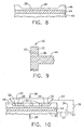
- Repair of such damage includes removing the damaged portion 48 from rib 46 to provide the second interface surface 28 described in connection with Figure 1 and shown in the fragmentary sectional views of Figures 5, 7 , 8 and 10 , identified above.
- the remaining portion of rib 46 then constituted the above-described second member 26, for example as represented in the fragmentary sectional views of Figures 7 , 8 and 9 .
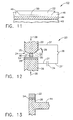
- a first or replacement member 22 in the fragmentary sectional views of Figures 9, 10 and 11 made of the above described Ru 60 alloy and including a first interface surface 24, is welded at fusion-type weld 50 using the method described in connection with Figure 1 .
- the embodiment of the fragmentary sectional view of Figure 10 shows several ignition members, for example Al free Ni wire segments, disposed between interface surfaces 24 and 28, the number selected depending on the length of interface surfaces 24 and 28.
- any excess portion of replacement member 22 can be removed appropriately using such well-known material removal methods as grinding, machining, etc. to blend with rib 46, to provide a welded article shown generally at 52 in the fragmentary sectional views of Figures 9 and 11 .
- Article 52 includes the first and second members 22 and 26, fusion welded at weld 50 across a narrow heat affected zone free of a substantially continuous layer of brittle intermetallic compounds.
- Another form of the present invention comprises including an interlayer or transition metal between first member 22 and second member 26.
- Such an interlayer can be used to act as a barrier or "getter” for such elements as Al that can diffuse at elevated temperatures, for example during gas turbine engine service operation, from second member 26 across weld 50 toward first member 22.
- the element Al at first member 22 at gas turbine engine operating temperatures can diffuse at the weld to form a substantially continuous layer of a brittle intermetallic compound that can result in cracking at the weld.
- such interlayer can bridge differences in mechanical or physical properties between the first and second members.
- An example of an alloy for such an interlayer is a substantially Al free Cr-Ni-Pd alloy.
- FIG. 12 The diagrammatic fragmentary view of Figure 12 is similar to the assembly and includes the same members and components as in the example of Figure 1 .
- Figure 12 shows an assembly 20 wherein second member 26 includes a third metal or alloy member 54 bonded to surface 28.
- Member or metal 54 is an interlayer between first member 22 and second member 26 in the article formed as a result of practice of the method form of the present invention.
- Third or interface member or metal 54 includes a third interface surface 56 disposed across gap 30 in juxtaposition with interface surface 24 of first member 22. Repeat of the practice of the method described in connection with Figure 1 resulted in the article shown in the fragmentary sectional view of Figure 13 .
- Such an article for example the blade tip of Figures 2 and 11 , included a welded replacement tip portion comprised of interlayer member 54 and first member 22 enhancing and repairing damage to the blade tip, as described above.
- Still other embodiments of the present invention comprise fusion welding at least one first member based on the first metal as an overlay to at least one lateral surface of an article.
- an overlay similar to a coating, can be welded through practice of the method of the present invention to a selected portion of the surface of blade airfoil 40 shown in Figure 2 .
- selected surface portions of a turbine blade airfoil can experience more strenuous high temperature environmental damage than do other surface portions.
- An example of such conditions and surface damage is described in U.S. Patent 6,042,880 - Rigney et al. and shown in the perspective diagrammatic view of present Figure 14 of a gas turbine engine blade 58 from the airfoil concave side. Typical discrete, local surface portion areas 60 and 62 more subject to damage are shown on the concave side of airfoil 40.
Landscapes
- Engineering & Computer Science (AREA)
- Mechanical Engineering (AREA)
- Pressure Welding/Diffusion-Bonding (AREA)
- Arc Welding In General (AREA)
- Laser Beam Processing (AREA)
- Turbine Rotor Nozzle Sealing (AREA)
Claims (3)
- Perkussions-Lichtbogen-Schmelzschweiß-Verfahren zum Verschweißen eines ersten Elements (22), das eine erste Grenzfläche (24) aufweist, mit einem zweiten Element (26), das eine zweite Grenzfläche (28) aufweist, wobei das Verfahren beinhaltet, die erste (24) und zweite (28) Grenzfläche so anzuordnen, dass sie in Kontakt mit einem Zündelement (32) stehen, das sich zwischen ihnen befindet, während sie einen elektrischen Strom durch die Grenzflächen (24, 28) und das Zündelement (32) leiten, der ausreicht, um das Zündelement (32) zu verdampfen und die Grenzflächen (24, 28) zusammenzudrücken und mittels Lichtbogen-Schmelzschweißen zu verbinden, wobei:das erste Element (22) aus einem elektrisch leitenden ersten Material auf der Basis von zumindest einem der Edelmetallelemente Ru, Rh, Pd und aluminiumfreien Pt hergestellt ist, das eine durchgehende Schicht einer spröden intermetallischen Verbindung an der ersten Grenzfläche (24) bilden kann;das zweite Element (26) aus einer elektrisch leitenden, aluminiumhaltigen Superlegierung auf Nickelbasis besteht;die erste und zweite Grenzfläche (24, 28) nahe beieinander auf gegenüberliegenden Seiten eines Spalts (30) angeordnet sind;zumindest ein aus einem dritten elektrisch leitenden, aluminiumfreien Metall hergestelltes Zündelement (32) in dem Spalt (30) angeordnet ist;eine Kraft (38) angewendet wird, um die erste und zweite Grenzfläche (24, 28) in die Richtung des zumindest einen Zündelements (32) und in Kontakt mit diesem zu drücken, um für einen elektrisch leitenden Pfad durch das erste Element (22), das zumindest eine Zündelement (32) und das zweite Element (26) zu sorgen, und wobei darüber hinausdas erste und zweite Element (22, 26) an der ersten (24) und zweiten Grenzfläche (28) schmelzverschweißt sind, in dem durch den elektrisch leitenden Pfad ein elektrischer Strom geleitet wird, und zwar mit einer Menge elektrischer Energie und über einen ersten Zeitraum, die ausreichen, um das zumindest eine Zündelement (32) zu einem Plasmastrahl zu verdampfen, der die erste (24) und zweite (28) Grenzfläche reinigt und ein Medium für einen Lichtbogen bildet, der so zwischen der ersten (24) und zweiten Grenzfläche (28) verlaufen und diese auf eine Fusionsschweißtemperatur erwärmen kann, während die Kraft (38) die erste (24) und zweite Grenzfläche (28) bewegt und miteinander in Kontakt bringt,wobei der erste Zeitraum kürzer als ein zweiter Zeitraum ist, der bei der Schmelzschweißtemperatur die Bildung der durchgehenden Schicht der spröden intermetallischen Verbindung an den Grenzflächen (24, 28) ermöglicht.
- Verfahren nach Anspruch 1, wobei eine Zwischenschicht aus aluminiumfreiem Metall (54) mit der zweiten Grenzfläche (28) des zweiten Elements (26) vor der Energieerzeugung verbunden wird, wobei die Zwischenschicht aus Metall (54) eine dritte Zwischenschicht-Grenzfläche (56) umfasst, und wobei die Energie an der ersten (24) und dritten (56) Oberfläche der Verbindung erzeugt wird.
- Verfahren nach Anspruch 1, zur Reparatur eines beschädigten Teils (48) eines Turbinentriebwerks-Beschaufelungselements (58), wobei das zweite Element (26) ein Schaufelblatt (40) ist, das den beschädigten Teil (48) umfasst, und das erste Element (22) ein Ersatzelement ist, das die erste Grenzfläche (24)umfasst, wobei:der beschädigte Teil (48) von dem zweiten Element (26) entfernt wird, um die zweite Grenzfläche (28) zur Verfügung zu stellen,das Ersatzelement (22) so angeordnet ist, dass die erste Grenzfläche (24) in Kontakt mit der zweiten Grenzfläche (28) steht, während die Energie erzeugt wird, um das Ersatzelement (22) mittels Schmelzschweißen an das Schaufelblatt (40) anzuschweißen.
Applications Claiming Priority (2)
| Application Number | Priority Date | Filing Date | Title |
|---|---|---|---|
| US10/699,405 US6994920B2 (en) | 2003-10-31 | 2003-10-31 | Fusion welding method and welded article |
| US699405 | 2003-10-31 |
Publications (2)
| Publication Number | Publication Date |
|---|---|
| EP1527839A1 EP1527839A1 (de) | 2005-05-04 |
| EP1527839B1 true EP1527839B1 (de) | 2009-10-07 |
Family
ID=34423450
Family Applications (1)
| Application Number | Title | Priority Date | Filing Date |
|---|---|---|---|
| EP04256647A Expired - Lifetime EP1527839B1 (de) | 2003-10-31 | 2004-10-27 | Abschmelzschweissverfahren und der daraus resultierende Artikel |
Country Status (6)
| Country | Link |
|---|---|
| US (1) | US6994920B2 (de) |
| EP (1) | EP1527839B1 (de) |
| JP (1) | JP4865206B2 (de) |
| BR (1) | BRPI0404753B1 (de) |
| DE (1) | DE602004023466D1 (de) |
| SG (1) | SG111244A1 (de) |
Families Citing this family (16)
| Publication number | Priority date | Publication date | Assignee | Title |
|---|---|---|---|---|
| JP4878127B2 (ja) | 2005-06-10 | 2012-02-15 | 株式会社トプコン | 時間差測定装置および距離測定装置並びに距離測定方法 |
| JP5465239B2 (ja) * | 2008-05-29 | 2014-04-09 | シーメンス アクチエンゲゼルシヤフト | 耐熱超合金から成るワークを溶接する方法と装置 |
| DE102008047043A1 (de) * | 2008-09-13 | 2010-03-18 | Mtu Aero Engines Gmbh | Ersatzteil für eine Gasturbinen-Schaufel einer Gasturbine, Gasturbinen-Schaufel sowie ein Verfahren zur Reparatur einer Gasturbinen-Schaufel |
| JP5438114B2 (ja) * | 2008-09-18 | 2014-03-12 | アイメック | 材料ボンディングのための方法およびシステム |
| US8726501B2 (en) * | 2009-08-31 | 2014-05-20 | General Electric Company | Method of welding single crystal turbine blade tips with an oxidation-resistant filler material |
| DE102009049518A1 (de) * | 2009-10-15 | 2011-04-21 | Fraunhofer-Gesellschaft zur Förderung der angewandten Forschung e.V. | Verfahren und Vorrichtung zum Schweißen von Werkstücken aus hochwarmfesten Superlegierungen |
| EP2322313A1 (de) * | 2009-11-13 | 2011-05-18 | Siemens Aktiengesellschaft | Verfahren zum Schweissen von Werkstücken aus hochwarmfesten Superlegierungen mit besonderer Massenzufuhrrate des Schweisszusatzwerkstoffes |
| US8753093B2 (en) | 2010-10-19 | 2014-06-17 | General Electric Company | Bonded turbine bucket tip shroud and related method |
| US9273562B2 (en) * | 2011-11-07 | 2016-03-01 | Siemens Energy, Inc. | Projection resistance welding of superalloys |
| US9186740B2 (en) | 2011-11-07 | 2015-11-17 | Siemens Energy, Inc. | Projection resistance brazing of superalloys |
| US9272350B2 (en) | 2012-03-30 | 2016-03-01 | Siemens Energy, Inc. | Method for resistance braze repair |
| US8910378B2 (en) * | 2012-05-01 | 2014-12-16 | United Technologies Corporation | Method for working of combustor float wall panels |
| US9085042B2 (en) | 2012-08-10 | 2015-07-21 | Siemens Energy, Inc. | Stud welding repair of superalloy components |
| EP2961555A4 (de) | 2013-02-28 | 2016-10-12 | United Technologies Corp | System und verfahren für schweissen bei niedriger temperatur |
| CN116181525B (zh) * | 2023-02-07 | 2023-08-15 | 中国人民解放军32804部队 | 一种增强燃油喷雾特性和化学活性的装置及方法 |
| CN119658120A (zh) * | 2024-11-18 | 2025-03-21 | 西安交通大学 | 一种抑制SiCp/Al界面反应的基于竞争相动力学设计的激光原位焊接方法 |
Family Cites Families (21)
| Publication number | Priority date | Publication date | Assignee | Title |
|---|---|---|---|---|
| US4305697A (en) * | 1980-03-19 | 1981-12-15 | General Electric Company | Method and replacement member for repairing a gas turbine engine vane assembly |
| US4657171A (en) * | 1985-06-13 | 1987-04-14 | General Electric Company | Repair of a member having a projection |
| US4808055A (en) * | 1987-04-15 | 1989-02-28 | Metallurgical Industries, Inc. | Turbine blade with restored tip |
| JP2754898B2 (ja) * | 1990-10-05 | 1998-05-20 | 日立電線株式会社 | Al―Fe系異種金属のスポット溶接法 |
| US5183390A (en) * | 1991-07-10 | 1993-02-02 | Westinghouse Electric Corp. | Method of forming a trailing edge on a steam turbine blade and the blade made thereby |
| JPH07164158A (ja) * | 1993-12-13 | 1995-06-27 | Mazda Motor Corp | 異種金属の接合方法 |
| JPH1147935A (ja) * | 1997-01-21 | 1999-02-23 | Sekisui Chem Co Ltd | 溶接方法及びパ−カッション溶接用部材 |
| US5794338A (en) * | 1997-04-04 | 1998-08-18 | General Electric Company | Method for repairing a turbine engine member damaged tip |
| US6084196A (en) * | 1998-02-25 | 2000-07-04 | General Electric Company | Elevated-temperature, plasma-transferred arc welding of nickel-base superalloy articles |
| JPH11342474A (ja) * | 1998-05-29 | 1999-12-14 | Sekisui Chem Co Ltd | 平板状部材の溶接方法 |
| US6042880A (en) * | 1998-12-22 | 2000-03-28 | General Electric Company | Renewing a thermal barrier coating system |
| US6020571A (en) | 1998-12-31 | 2000-02-01 | General Electric Company | Welding method and apparatus therefor |
| US6158955A (en) * | 1999-06-03 | 2000-12-12 | General Electric Company | Welding method and assembly therefor |
| US6335512B1 (en) * | 1999-07-13 | 2002-01-01 | General Electric Company | X-ray device comprising a crack resistant weld |
| US6384365B1 (en) * | 2000-04-14 | 2002-05-07 | Siemens Westinghouse Power Corporation | Repair and fabrication of combustion turbine components by spark plasma sintering |
| US6532656B1 (en) * | 2001-10-10 | 2003-03-18 | General Electric Company | Gas turbine engine compressor blade restoration method |
| US6575702B2 (en) * | 2001-10-22 | 2003-06-10 | General Electric Company | Airfoils with improved strength and manufacture and repair thereof |
| US6596411B2 (en) | 2001-12-06 | 2003-07-22 | General Electric Company | High energy beam welding of single-crystal superalloys and assemblies formed thereby |
| JP2003222026A (ja) * | 2002-01-30 | 2003-08-08 | Hitachi Ltd | タービン翼の製作方法およびタービン翼 |
| JP3941001B2 (ja) * | 2002-06-20 | 2007-07-04 | トヨタ自動車株式会社 | 異種金属材料の接合方法 |
| US6914210B2 (en) | 2002-10-30 | 2005-07-05 | General Electric Company | Method of repairing a stationary shroud of a gas turbine engine using plasma transferred arc welding |
-
2003
- 2003-10-31 US US10/699,405 patent/US6994920B2/en not_active Expired - Fee Related
-
2004
- 2004-10-22 SG SG200406161A patent/SG111244A1/en unknown
- 2004-10-26 BR BRPI0404753-2B1A patent/BRPI0404753B1/pt not_active IP Right Cessation
- 2004-10-27 DE DE602004023466T patent/DE602004023466D1/de not_active Expired - Lifetime
- 2004-10-27 EP EP04256647A patent/EP1527839B1/de not_active Expired - Lifetime
- 2004-10-29 JP JP2004315278A patent/JP4865206B2/ja not_active Expired - Fee Related
Also Published As
| Publication number | Publication date |
|---|---|
| BRPI0404753B1 (pt) | 2013-11-19 |
| JP2005169500A (ja) | 2005-06-30 |
| DE602004023466D1 (de) | 2009-11-19 |
| BRPI0404753A (pt) | 2005-06-21 |
| US20050092717A1 (en) | 2005-05-05 |
| SG111244A1 (en) | 2005-05-30 |
| EP1527839A1 (de) | 2005-05-04 |
| US6994920B2 (en) | 2006-02-07 |
| JP4865206B2 (ja) | 2012-02-01 |
Similar Documents
| Publication | Publication Date | Title |
|---|---|---|
| US6994920B2 (en) | Fusion welding method and welded article | |
| US4657171A (en) | Repair of a member having a projection | |
| JP4318140B2 (ja) | プラズマ移行性アーク溶接を使用してガスタービンエンジンの固定シュラウドを修理する方法 | |
| EP0999009B1 (de) | Verfahren zum Aufbringen von verschleissfesten Materialen auf Turbinenschaufeln | |
| JP4731002B2 (ja) | 超合金溶接組成物及び補修タービンエンジン部品 | |
| US7051435B1 (en) | Process for repairing turbine components | |
| KR100757549B1 (ko) | 초합금 용접용 조성물 및 보수된 터빈 엔진의 구성요소 | |
| JP4912533B2 (ja) | シムを用いる電子ビーム溶接方法 | |
| EP4105438B1 (de) | Klebeverfahren für die reparatur eines gasturbinentriebwerk-bauteils | |
| EP2298489A1 (de) | Superlegierungszusammensetzung und Verfahren zur Herstellung einer Turbinenmotorkomponente | |
| US9186740B2 (en) | Projection resistance brazing of superalloys | |
| CA2657005A1 (en) | Method for repairing and/or replacing individual elements of a gas turbine component | |
| JP2011064077A (ja) | ガスタービン部品およびその補修方法 | |
| JP3686319B2 (ja) | ガスタービン動翼の溶接方法 | |
| Ellison et al. | Powder metallurgy repair of turbine components | |
| US20140099516A1 (en) | Brazed articles and methods of making the same | |
| EP1512482B1 (de) | Verfahren zum verbesserten Schweisseindringen durch Bildung einer Oxidschicht und daraus resultiertes Produkt. | |
| US12042875B2 (en) | Weld-brazing techniques | |
| JP2022517631A5 (de) | ||
| JPS59180004A (ja) | 蒸気タ−ビン動翼 |
Legal Events
| Date | Code | Title | Description |
|---|---|---|---|
| PUAI | Public reference made under article 153(3) epc to a published international application that has entered the european phase |
Free format text: ORIGINAL CODE: 0009012 |
|
| AK | Designated contracting states |
Kind code of ref document: A1 Designated state(s): AT BE BG CH CY CZ DE DK EE ES FI FR GB GR HU IE IT LI LU MC NL PL PT RO SE SI SK TR |
|
| AX | Request for extension of the european patent |
Extension state: AL HR LT LV MK |
|
| 17P | Request for examination filed |
Effective date: 20051104 |
|
| AKX | Designation fees paid |
Designated state(s): DE FR GB IT |
|
| APBN | Date of receipt of notice of appeal recorded |
Free format text: ORIGINAL CODE: EPIDOSNNOA2E |
|
| APBR | Date of receipt of statement of grounds of appeal recorded |
Free format text: ORIGINAL CODE: EPIDOSNNOA3E |
|
| APBV | Interlocutory revision of appeal recorded |
Free format text: ORIGINAL CODE: EPIDOSNIRAPE |
|
| GRAP | Despatch of communication of intention to grant a patent |
Free format text: ORIGINAL CODE: EPIDOSNIGR1 |
|
| GRAS | Grant fee paid |
Free format text: ORIGINAL CODE: EPIDOSNIGR3 |
|
| GRAA | (expected) grant |
Free format text: ORIGINAL CODE: 0009210 |
|
| AK | Designated contracting states |
Kind code of ref document: B1 Designated state(s): DE FR GB IT |
|
| REG | Reference to a national code |
Ref country code: GB Ref legal event code: FG4D |
|
| REF | Corresponds to: |
Ref document number: 602004023466 Country of ref document: DE Date of ref document: 20091119 Kind code of ref document: P |
|
| PLBE | No opposition filed within time limit |
Free format text: ORIGINAL CODE: 0009261 |
|
| STAA | Information on the status of an ep patent application or granted ep patent |
Free format text: STATUS: NO OPPOSITION FILED WITHIN TIME LIMIT |
|
| 26N | No opposition filed |
Effective date: 20100708 |
|
| PGFP | Annual fee paid to national office [announced via postgrant information from national office to epo] |
Ref country code: GB Payment date: 20141027 Year of fee payment: 11 Ref country code: DE Payment date: 20141029 Year of fee payment: 11 Ref country code: FR Payment date: 20141017 Year of fee payment: 11 |
|
| PGFP | Annual fee paid to national office [announced via postgrant information from national office to epo] |
Ref country code: IT Payment date: 20141028 Year of fee payment: 11 |
|
| REG | Reference to a national code |
Ref country code: DE Ref legal event code: R119 Ref document number: 602004023466 Country of ref document: DE |
|
| GBPC | Gb: european patent ceased through non-payment of renewal fee |
Effective date: 20151027 |
|
| PG25 | Lapsed in a contracting state [announced via postgrant information from national office to epo] |
Ref country code: DE Free format text: LAPSE BECAUSE OF NON-PAYMENT OF DUE FEES Effective date: 20160503 Ref country code: IT Free format text: LAPSE BECAUSE OF NON-PAYMENT OF DUE FEES Effective date: 20151027 Ref country code: GB Free format text: LAPSE BECAUSE OF NON-PAYMENT OF DUE FEES Effective date: 20151027 |
|
| REG | Reference to a national code |
Ref country code: FR Ref legal event code: ST Effective date: 20160630 |
|
| PG25 | Lapsed in a contracting state [announced via postgrant information from national office to epo] |
Ref country code: FR Free format text: LAPSE BECAUSE OF NON-PAYMENT OF DUE FEES Effective date: 20151102 |