EP1527832A1 - Stanzwerkzeug mit zwei C-Profilen - Google Patents
Stanzwerkzeug mit zwei C-Profilen Download PDFInfo
- Publication number
- EP1527832A1 EP1527832A1 EP04021862A EP04021862A EP1527832A1 EP 1527832 A1 EP1527832 A1 EP 1527832A1 EP 04021862 A EP04021862 A EP 04021862A EP 04021862 A EP04021862 A EP 04021862A EP 1527832 A1 EP1527832 A1 EP 1527832A1
- Authority
- EP
- European Patent Office
- Prior art keywords
- profile
- die
- punching
- profiles
- punching device
- Prior art date
- Legal status (The legal status is an assumption and is not a legal conclusion. Google has not performed a legal analysis and makes no representation as to the accuracy of the status listed.)
- Granted
Links
- 238000004080 punching Methods 0.000 claims abstract description 53
- 238000000034 method Methods 0.000 claims description 5
- 210000002414 leg Anatomy 0.000 description 27
- 238000004519 manufacturing process Methods 0.000 description 4
- 238000005516 engineering process Methods 0.000 description 3
- 210000000689 upper leg Anatomy 0.000 description 3
- 230000006978 adaptation Effects 0.000 description 2
- 238000010276 construction Methods 0.000 description 2
- 230000004323 axial length Effects 0.000 description 1
- 230000015572 biosynthetic process Effects 0.000 description 1
- 238000009435 building construction Methods 0.000 description 1
- 150000001875 compounds Chemical class 0.000 description 1
- 230000018109 developmental process Effects 0.000 description 1
- 230000000694 effects Effects 0.000 description 1
- 238000005755 formation reaction Methods 0.000 description 1
- 230000001788 irregular Effects 0.000 description 1
- 238000003754 machining Methods 0.000 description 1
- 239000011159 matrix material Substances 0.000 description 1
- 238000000465 moulding Methods 0.000 description 1
- -1 punched joints Chemical class 0.000 description 1
Images



Classifications
-
- B—PERFORMING OPERATIONS; TRANSPORTING
- B21—MECHANICAL METAL-WORKING WITHOUT ESSENTIALLY REMOVING MATERIAL; PUNCHING METAL
- B21J—FORGING; HAMMERING; PRESSING METAL; RIVETING; FORGE FURNACES
- B21J15/00—Riveting
- B21J15/10—Riveting machines
-
- B—PERFORMING OPERATIONS; TRANSPORTING
- B21—MECHANICAL METAL-WORKING WITHOUT ESSENTIALLY REMOVING MATERIAL; PUNCHING METAL
- B21D—WORKING OR PROCESSING OF SHEET METAL OR METAL TUBES, RODS OR PROFILES WITHOUT ESSENTIALLY REMOVING MATERIAL; PUNCHING METAL
- B21D39/00—Application of procedures in order to connect objects or parts, e.g. coating with sheet metal otherwise than by plating; Tube expanders
- B21D39/03—Application of procedures in order to connect objects or parts, e.g. coating with sheet metal otherwise than by plating; Tube expanders of sheet metal otherwise than by folding
- B21D39/031—Joining superposed plates by locally deforming without slitting or piercing
-
- B—PERFORMING OPERATIONS; TRANSPORTING
- B21—MECHANICAL METAL-WORKING WITHOUT ESSENTIALLY REMOVING MATERIAL; PUNCHING METAL
- B21J—FORGING; HAMMERING; PRESSING METAL; RIVETING; FORGE FURNACES
- B21J15/00—Riveting
- B21J15/02—Riveting procedures
- B21J15/025—Setting self-piercing rivets
Definitions
- the invention relates to a punching device for simultaneous connection a hollow profile on each of two opposite sides with each a flat component by means of a deforming fastening technology as punching, riveting or clinching, wherein the punching a Holding device in the form of an E-profile, the middle Leg during connection in the hollow profile protrudes and a first female carries in cooperation with one in the outer Legs of the E-profile arranged first stamp the connection of the Hollow profile with the first flat component causes, as well as a second Die in cooperation with one in the other outer thigh the E-profile arranged second punch the connection of the hollow profile effected with the second flat component.
- a deforming fastening technology as punching, riveting or clinching
- Such a punching device is known from DE 41 34 414 A1.
- Such punching devices with E-profiles as a holding device for The punching tools are used wherever in hollow sections simultaneously on two opposite sides deforming connections with other components are created should, for example, when riveting U-shaped profile Prefabricated parts in building construction, wherever to create walls a whole series of similar components juxtaposed and must be attached.
- a mounting device in the form of a single C-profile is provided, on one leg of a die and on the opposite leg cooperating with the die Stamp is provided.
- This is usually hydraulically driven and is for example, in the construction of a riveted joint with a rivet Mistake.
- a known device forming Compounds such as punched joints, riveted joints or Although clinch connections are easily made, and so are Hollow profiles with very different inner diameters and Moldings workable, however, only one can ever Liaison office at a given time.
- the matrices rigid and with a fixed axial length can be designed in the improved punching devices with E-profile usually with axial in their Length adjustable matrices worked, so that on the one hand from the inside of the hollow profile approached to be processed connection points can be, on the other hand, hollow sections of different Diameter can be processed without the Retaining device and the tools located thereon exchanged would have to be.
- Object of the present invention is in contrast, a Punching device of the type described above with the simplest possible technical means to improve, that on the one hand, how at the facilities with the E-profile bracket devices two Deforming connections simultaneously on opposite sides a hollow profile can be attached, but on the other hand a Adaptation to different shapes and diameters of hollow profiles can be effected with simpler means and thereby also a less expensive production of the holding device for the tools and thus the entire punching device is made possible.
- this object is also surprisingly simple how effective way solved by that the e-profile of the Mounting device of a first and a second C-profile is constructed, wherein the first C-profile at its the second C-profile adjacent leg the first die and the second C-profile at his the second C-profile adjacent leg carries the second die, and wherein at the free leg of the first C-profile of the first punch and on free leg of the second C-profile of the second punch is arranged, and that the first and the second C-profile in the punching direction against each other are movable.
- the two mutually movable C-profiles allow a very high flexibility and adaptability to different types of too machining hollow sections and are on the other hand because of their simple Build more cost-effective to manufacture than the known ones Holding devices in the form of E-profiles. Due to the The matrixes can be moved in the axial punching direction of the C-profiles on the two adjoining legs of the two C-profiles be made rigid as in the known simple Punching devices where only a single C-profile use finds, but in contrast to the punching device according to the invention generate only one single deforming connection at a time can.
- the C-profiles are independent movable from one another, so that also unbalanced or irregular Forms of hollow profiles can be edited arbitrarily.
- the C-profiles are common, preferably moved symmetrically to one another. Even with it can be large areas of different inside diameters of hollow sections cover, but only if they are built semi-symmetrical are. But this embodiment is much cheaper Can be produced as the above with an independent mobility the C-profiles. In particular, the drive technology can do a lot here be designed simpler.
- Hollow profiles For simultaneous processing of two opposite sides of a Hollow profiles is either the hollow profile with the two adjacent to connecting components, at least in the field of Connecting points are flat, in other areas, however more or less arbitrarily shaped, over the neighboring ones Thighs of the two C-profiles slipped, which on the minimal possible distance approached each other.
- the two adjacent legs of the C-profiles in the cavity of the machined Hollow profiles enter and then the stamp on the two free outer leg of the C-profiles against the now within the Hollow profile positioned to move dies and thus on both Pages to create the deforming connections.
- Punching device is provided that the first C-profile at his the second C-profile adjacent leg having a groove or channel, in which of the first C-profile adjacent leg of the second C-profile in the contracted state of the two C-profiles at least partially is recorded.
- This allows the two C-profiles to a certain extent be moved overlapping so that the middle leg of the thus formed "two-part E-profile" a particularly low Has expansion in the punching direction. That way too Hollow profiles are processed with very small inner diameters.
- Punching device provided a locking device by means of which the first C-profile at a preselectable fixed distance from the second C-profile can be held.
- a development of this embodiment is characterized in that the punching device with locked distance between the first and The second C-profile is movable in total. This is especially true of Advantage if the hollow sections to be machined do not have a rigid in itself mounted support device are slipped, but if the Holder device is to be moved into the cavities of the profiles. Due to the locking of the distance between the two C-profiles does not have to be readjusted each time the mutual distance.
- An embodiment of the invention is also particularly advantageous Punching device according to the invention, in which at least the first die, preferably also the second die rigid and without the possibility of a Length change is constructed. This can increase the life of the Matrices due to significantly less wear, as above be discussed, significantly extended.
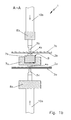
- the figures of the drawing show an embodiment of the Punching device 1 according to the invention for simultaneously connecting a Hollow sections 2; 2 'on opposite sides 2a, 2b; 2a ', 2b' with a respectively applied thereto component 3a, 3b by means of a deforming fastening technology such as punching, riveting or clinching.
- a deforming fastening technology such as punching, riveting or clinching.
- components 3a, 3b may be flat outside of Connection area in a variety of forms are present.
- the punching device 1 comprises a Mounting device consisting of a first C-profile 6a and a second C-profile 6b is constructed.
- the first C-profile 6a carries on his the second C-profile 6b adjacent leg 7a a first die 4a and the second C-profile 6b adjacent to the first C-profile 6a Leg 7b a second die 4b.
- outer leg 8a of first C-profile 6a is a first punch 5a and the free outer Leg 8b of the second C-profile 6b a second punch 5b arranged in each case in cooperation with the corresponding die 4a, 4b simultaneously each a connection of the two opposite sides 2a, 2b; 2a ', 2b' with the respectively lying there flat components 3a, 3b effect.
- FIGS. 1a, 1b this is for a Hollow profile 2 shown with a relatively small inner diameter, so that the both C-profiles 6a, 6b have moved together to a minimum distance.
- FIGS. 2a and 2b show an example of a hollow profile 2 ', its opposite sides 2a ', 2b' a greater distance have from each other.
- Tools are achieved are by means of a generally hydraulically operating device, of which in the drawing only schematically the hydraulic cylinder 10a, 10b are shown, the two punches 5a, 5b against the corresponding Matrices 4a, 4b method to a corresponding deforming Connection between the sides 2a, 2b and 2a ', 2b' of the hollow section 2; 2 ' and to each adjacent flat components 3a, 3b to cause.
- Fig. 2b are the both C-profiles 6a, 6b in the extended state at the Processing a hollow profile 2 'with a larger inner diameter shown.
- a (not shown) locking device may be provided by means of which the first C-profile 6a at a preselectable fixed distance from the second C-profile 6b can be kept. In particular, can be locked in this Position the entire mounting device with the thereon Punching tools relative to the hollow sections to be machined both in Punching direction and be moved radially in one direction.
Landscapes
- Engineering & Computer Science (AREA)
- Mechanical Engineering (AREA)
- Insertion Pins And Rivets (AREA)
- Punching Or Piercing (AREA)
Abstract
Description
- Fig. 1a
- eine schematische Seitenansicht in horizontaler Richtung auf eine Ausführungsform der erfindungsgemäßen Stanzeinrichtung mit vertikal angeordneter Stanzachse, bei der die benachbarten Schenkel der beiden C-Profile auf minimale Distanz zusammengefahren sind;
- Fig. 1b
- einen Vertikalschnitt durch die Ebene A-A der Vorrichtung nach Fig. 1a;
- Fig. 2a
- die Vorrichtung nach Fig. 1a mit in Stanzrichtung auseinander gefahrenen C-Profilen; und
- Fig. 2b
- einen Vertikalschnitt durch die Ebene B-B der Stanzeinrichtung nach Fig. 2a.
Claims (8)
- Stanzeinrichtung zum simultanen Verbinden eines Hohlprofils (2; 2') an jeweils zwei gegenüberliegenden Seiten (2a, 2b; 2a', 2b') mit jeweils einem flachen Bauelement (3a, 3b) mittels einer verformenden Befestigungstechnik wie Stanzen, Nieten oder Clinchen, wobei die Stanzeinrichtung eine Halterungsvorrichtung in Form eines E-Profils aufweist, dessen mittlerer Schenkel während des Verbindens in das Hohlprofil (2; 2') hineinragt und eine erste Matrize (4a) trägt, die in Zusammenwirkung mit einem in einem der beiden äußeren Schenkel des E-Profils angeordneten ersten Stempel (5a) die Verbindung des Hohlprofils (2; 2') mit dem ersten flachen Bauelement (3a) bewirkt, sowie eine zweite Matrize (4b), die in Zusammenwirkung mit einem im anderen äußeren Schenkel des E-Profils angeordneten zweiten Stempel (5b) die Verbindung des Hohlprofils (2; 2') mit dem zweiten flachen Bauelement (3b) bewirkt,
dadurch gekennzeichnet, dass das E-Profil der Halterungsvorrichtung aus einem ersten C-Profil (6a) und einem zweiten C-Profil (6b) aufgebaut ist, wobei das erste C-Profil (6a) an seinem dem zweiten C-Profil (6b) benachbarten Schenkel (7a) die erste Matrize (4a) und das zweite C-Profil (6b) an seinem dem ersten C-Profil (6a) benachbarten Schenkel (7b) die zweite Matrize (4b) trägt, und wobei am freien, äußeren Schenkel (8a) des ersten C-Profils (6a) der erste Stempel (5a) und am freien, äußeren Schenkel (8b) des zweiten C-Profils (6b) der zweite Stempel (5b) angeordnet ist, und dass das erste C-Profil (6a) und das zweite C-Profil (6b) in Stanzrichtung gegeneinander verfahrbar sind. - Stanzeinrichtung nach Anspruch 1, dadurch gekennzeichnet, dass die C-Profile (6a, 6b) unabhängig voneinander verfahrbar sind.
- Stanzeinrichtung nach Anspruch 1, dadurch gekennzeichnet, dass die C-Profile (6a, 6b) gemeinsam, vorzugsweise symmetrisch zueinander verfahrbar sind.
- Stanzeinrichtung nach einem der vorhergehenden Ansprüche, dadurch gekennzeichnet, dass zumindest die erste Matrize (4a), vorzugsweise auch die zweite Matrize (4b) starr, insbesondere ohne die Möglichkeit einer Längenänderung aufgebaut ist.
- Stanzeinrichtung nach einem der Ansprüche 1 bis 3, dadurch gekennzeichnet, dass zumindest die erste Matrize (4a), längenverstellbar aufgebaut ist.
- Stanzeinrichtung nach einem der vorhergehenden Ansprüche, dadurch gekennzeichnet, dass das erste C-Profil (6a) an seinem dem zweiten C-Profil (6b) benachbarten Schenkel (7a) eine Nut oder Rinne (9) aufweist, in welcher der dem ersten C-Profil (6a) benachbarte Schenkel (7b) des zweiten C-Profils (6b) im zusammengefahrenen Zustand der beiden C-Profile (6a, 6b) zumindest teilweise aufgenommen wird.
- Stanzeinrichtung nach einem der vorhergehenden Ansprüche, dadurch gekennzeichnet, dass eine Arretiervorrichtung vorgesehen ist, mittels derer das erste C-Profil (6a) in einem vorwählbaren festen Abstand vom zweiten C-Profil (6b) gehalten werden kann.
- Stanzeinrichtung nach Anspruch 7, dadurch gekennzeichnet, dass die Stanzeinrichtung (1) mit arretiertem Abstand zwischen dem ersten C-Profil (6a) und dem zweiten C-Profil (6b) insgesamt verfahrbar ist.
Applications Claiming Priority (2)
| Application Number | Priority Date | Filing Date | Title |
|---|---|---|---|
| DE2003150157 DE10350157B3 (de) | 2003-10-28 | 2003-10-28 | Stanzwerkzeug mit zwei C-Profilen |
| DE10350157 | 2003-10-28 |
Publications (2)
| Publication Number | Publication Date |
|---|---|
| EP1527832A1 true EP1527832A1 (de) | 2005-05-04 |
| EP1527832B1 EP1527832B1 (de) | 2006-12-20 |
Family
ID=33441839
Family Applications (1)
| Application Number | Title | Priority Date | Filing Date |
|---|---|---|---|
| EP20040021862 Expired - Lifetime EP1527832B1 (de) | 2003-10-28 | 2004-09-15 | Stanzwerkzeug mit zwei C-Profilen |
Country Status (2)
| Country | Link |
|---|---|
| EP (1) | EP1527832B1 (de) |
| DE (2) | DE10350157B3 (de) |
Cited By (3)
| Publication number | Priority date | Publication date | Assignee | Title |
|---|---|---|---|---|
| WO2012087100A1 (es) * | 2010-12-21 | 2012-06-28 | Metalsa, S. A. De C. V. | Sistema para perforar alas de perfiles estructurales largos |
| CN103143923A (zh) * | 2013-03-19 | 2013-06-12 | 无锡威孚力达催化净化器有限责任公司 | Poc载体封装高速穿孔机 |
| CN105798180A (zh) * | 2016-05-06 | 2016-07-27 | 安徽鲲鹏装备模具制造有限公司 | 一种壳体铆接设备 |
Families Citing this family (2)
| Publication number | Priority date | Publication date | Assignee | Title |
|---|---|---|---|---|
| CN103272917B (zh) * | 2013-06-07 | 2015-06-17 | 佛山市顺德区科贝隆塑料机械有限公司 | 快速线槽自动冲孔机 |
| DE102016216110A1 (de) | 2016-08-26 | 2018-03-01 | Volkswagen Aktiengesellschaft | Fügeeinrichtung |
Citations (4)
| Publication number | Priority date | Publication date | Assignee | Title |
|---|---|---|---|---|
| US4136592A (en) * | 1976-06-01 | 1979-01-30 | Beatty Machine & Manufacturing Co. | Apparatus for one-pass punching of beams |
| US5063804A (en) * | 1990-03-20 | 1991-11-12 | Peddinghaus Corporation | Offset punch press assembly for structural beams |
| DE4134414A1 (de) * | 1991-10-17 | 1993-04-22 | Knuerr Mechanik Ag | Vorrichtung zum nietartigen verbinden von blechartigen teilen |
| US20020121124A1 (en) * | 2001-03-02 | 2002-09-05 | Estes Stephen R. | Dual notcher |
-
2003
- 2003-10-28 DE DE2003150157 patent/DE10350157B3/de not_active Expired - Fee Related
-
2004
- 2004-09-15 DE DE200450002362 patent/DE502004002362D1/de not_active Expired - Lifetime
- 2004-09-15 EP EP20040021862 patent/EP1527832B1/de not_active Expired - Lifetime
Patent Citations (4)
| Publication number | Priority date | Publication date | Assignee | Title |
|---|---|---|---|---|
| US4136592A (en) * | 1976-06-01 | 1979-01-30 | Beatty Machine & Manufacturing Co. | Apparatus for one-pass punching of beams |
| US5063804A (en) * | 1990-03-20 | 1991-11-12 | Peddinghaus Corporation | Offset punch press assembly for structural beams |
| DE4134414A1 (de) * | 1991-10-17 | 1993-04-22 | Knuerr Mechanik Ag | Vorrichtung zum nietartigen verbinden von blechartigen teilen |
| US20020121124A1 (en) * | 2001-03-02 | 2002-09-05 | Estes Stephen R. | Dual notcher |
Cited By (3)
| Publication number | Priority date | Publication date | Assignee | Title |
|---|---|---|---|---|
| WO2012087100A1 (es) * | 2010-12-21 | 2012-06-28 | Metalsa, S. A. De C. V. | Sistema para perforar alas de perfiles estructurales largos |
| CN103143923A (zh) * | 2013-03-19 | 2013-06-12 | 无锡威孚力达催化净化器有限责任公司 | Poc载体封装高速穿孔机 |
| CN105798180A (zh) * | 2016-05-06 | 2016-07-27 | 安徽鲲鹏装备模具制造有限公司 | 一种壳体铆接设备 |
Also Published As
| Publication number | Publication date |
|---|---|
| EP1527832B1 (de) | 2006-12-20 |
| DE10350157B3 (de) | 2004-12-09 |
| DE502004002362D1 (de) | 2007-02-01 |
Similar Documents
| Publication | Publication Date | Title |
|---|---|---|
| DE69003281T2 (de) | Vorrichtung zum Stanzen oder Formen mit Kniehebeln für die hin- und hergehende Bewegung der Werkzeuge. | |
| DE2830690C2 (de) | Verfahren zur mechanischen Herstellung einer leckdichten Rohrverbindung | |
| EP1003616A1 (de) | Vorrichtung und verfahren zum verformen, insbesondere zum kaltverformen, von werkstücken | |
| DE10162159B4 (de) | Linearstellglied mit Stoßdämpfungsmechanismus | |
| EP2179191B1 (de) | Kupplungsglied für eine mitnehmerkupplung und herstellungsverfahren | |
| EP1757381B1 (de) | Verfahren und Vorrichtung zum drehfesten Verbinden einer Hohlwelle mit einem Bauteil | |
| EP1117497B1 (de) | Fügevorrichtung, durchsetzfügeverfahren und durchsetzfügeverbindung | |
| DE10350157B3 (de) | Stanzwerkzeug mit zwei C-Profilen | |
| DE3512241A1 (de) | Radialpresse | |
| DE4107709A1 (de) | Stanzpressenanordnung fuer stahltraeger | |
| DE69419206T2 (de) | Verfahren und Vorrichtung zum Herstellen eines metallischen Teils | |
| DE4444857C1 (de) | Verfahren und Vorrichtung zur Herstellung mindestens einer Öffnung in der Wandung eines rohrartigen Teils | |
| EP1878550A1 (de) | Spindeleinheit für ein mehrspindeliges Bohraggregat | |
| DE102020104529B4 (de) | Vorrichtung und Verfahren zum mechanischen Fügen von Hohlprofilen | |
| DE2655323A1 (de) | Vorrichtung zum umformen eines einzelnen, metallischen werkstuecks | |
| EP0906800A1 (de) | Verfahren und Vorrichtung zum Herstellen einer Hohlwelle mit äusseren radialen Erhebungen durch Innenhochdruck-Umformung | |
| EP1291121A2 (de) | Befestigungsverfahren, Montagewerkzeug und Stützhebel für ein Schaltschloss eines Leistungsschalters, bzw. Lasttrennschalters | |
| DE60101708T2 (de) | Montagesystem für Komponenten | |
| EP2994652B1 (de) | Linearantrieb und verfahren zu seiner herstellung | |
| EP4323132B1 (de) | Verfahren zur herstellung eines ein verzahnungsprofil aufweisenden bauteils; sowie werkzeugvorrichtung | |
| DE102006052830A1 (de) | Verfahren und Vorrichtung zum Biegen von Profilen mit überlagerter Schmiedeumformung | |
| CH647170A5 (en) | Process for the production of a channel | |
| EP0892689B1 (de) | Verfahren zum erhöhen der wandungsstärke bei hohlprofilen | |
| EP2279811B1 (de) | Arbeitsmaschine mit Quertransportvorrichtung und Verfahren zum Herstellen einer Hülse unter Verwendung der Arbeitsmaschine | |
| DE102006012625A1 (de) | Verfahren zur Herstellung von Profilen |
Legal Events
| Date | Code | Title | Description |
|---|---|---|---|
| PUAI | Public reference made under article 153(3) epc to a published international application that has entered the european phase |
Free format text: ORIGINAL CODE: 0009012 |
|
| AK | Designated contracting states |
Kind code of ref document: A1 Designated state(s): AT BE BG CH CY CZ DE DK EE ES FI FR GB GR HU IE IT LI LU MC NL PL PT RO SE SI SK TR |
|
| AX | Request for extension of the european patent |
Extension state: AL HR LT LV MK |
|
| 17P | Request for examination filed |
Effective date: 20050709 |
|
| AKX | Designation fees paid |
Designated state(s): DE FR GB IE SE |
|
| GRAP | Despatch of communication of intention to grant a patent |
Free format text: ORIGINAL CODE: EPIDOSNIGR1 |
|
| GRAS | Grant fee paid |
Free format text: ORIGINAL CODE: EPIDOSNIGR3 |
|
| GRAA | (expected) grant |
Free format text: ORIGINAL CODE: 0009210 |
|
| AK | Designated contracting states |
Kind code of ref document: B1 Designated state(s): DE FR GB IE SE |
|
| REG | Reference to a national code |
Ref country code: GB Ref legal event code: FG4D Free format text: NOT ENGLISH |
|
| REF | Corresponds to: |
Ref document number: 502004002362 Country of ref document: DE Date of ref document: 20070201 Kind code of ref document: P |
|
| REG | Reference to a national code |
Ref country code: IE Ref legal event code: FG4D Free format text: LANGUAGE OF EP DOCUMENT: GERMAN |
|
| GBT | Gb: translation of ep patent filed (gb section 77(6)(a)/1977) |
Effective date: 20070314 |
|
| REG | Reference to a national code |
Ref country code: SE Ref legal event code: TRGR |
|
| ET | Fr: translation filed | ||
| PLBE | No opposition filed within time limit |
Free format text: ORIGINAL CODE: 0009261 |
|
| STAA | Information on the status of an ep patent application or granted ep patent |
Free format text: STATUS: NO OPPOSITION FILED WITHIN TIME LIMIT |
|
| 26N | No opposition filed |
Effective date: 20070921 |
|
| PGFP | Annual fee paid to national office [announced via postgrant information from national office to epo] |
Ref country code: IE Payment date: 20100910 Year of fee payment: 7 |
|
| PGFP | Annual fee paid to national office [announced via postgrant information from national office to epo] |
Ref country code: FR Payment date: 20100902 Year of fee payment: 7 Ref country code: SE Payment date: 20100927 Year of fee payment: 7 |
|
| PGFP | Annual fee paid to national office [announced via postgrant information from national office to epo] |
Ref country code: GB Payment date: 20100819 Year of fee payment: 7 |
|
| PGFP | Annual fee paid to national office [announced via postgrant information from national office to epo] |
Ref country code: DE Payment date: 20101006 Year of fee payment: 7 |
|
| GBPC | Gb: european patent ceased through non-payment of renewal fee |
Effective date: 20110915 |
|
| REG | Reference to a national code |
Ref country code: IE Ref legal event code: MM4A |
|
| REG | Reference to a national code |
Ref country code: FR Ref legal event code: ST Effective date: 20120531 |
|
| REG | Reference to a national code |
Ref country code: SE Ref legal event code: EUG |
|
| REG | Reference to a national code |
Ref country code: DE Ref legal event code: R119 Ref document number: 502004002362 Country of ref document: DE Effective date: 20120403 |
|
| PG25 | Lapsed in a contracting state [announced via postgrant information from national office to epo] |
Ref country code: IE Free format text: LAPSE BECAUSE OF NON-PAYMENT OF DUE FEES Effective date: 20110915 Ref country code: DE Free format text: LAPSE BECAUSE OF NON-PAYMENT OF DUE FEES Effective date: 20120403 |
|
| PG25 | Lapsed in a contracting state [announced via postgrant information from national office to epo] |
Ref country code: FR Free format text: LAPSE BECAUSE OF NON-PAYMENT OF DUE FEES Effective date: 20110930 Ref country code: GB Free format text: LAPSE BECAUSE OF NON-PAYMENT OF DUE FEES Effective date: 20110915 |
|
| PG25 | Lapsed in a contracting state [announced via postgrant information from national office to epo] |
Ref country code: SE Free format text: LAPSE BECAUSE OF NON-PAYMENT OF DUE FEES Effective date: 20110916 |