EP1527709A1 - Haarpflegegerät mit Ionisationsvorrichtung - Google Patents
Haarpflegegerät mit Ionisationsvorrichtung Download PDFInfo
- Publication number
- EP1527709A1 EP1527709A1 EP04023317A EP04023317A EP1527709A1 EP 1527709 A1 EP1527709 A1 EP 1527709A1 EP 04023317 A EP04023317 A EP 04023317A EP 04023317 A EP04023317 A EP 04023317A EP 1527709 A1 EP1527709 A1 EP 1527709A1
- Authority
- EP
- European Patent Office
- Prior art keywords
- hair care
- care appliance
- electrode
- appliance according
- high voltage
- Prior art date
- Legal status (The legal status is an assumption and is not a legal conclusion. Google has not performed a legal analysis and makes no representation as to the accuracy of the status listed.)
- Granted
Links
- 239000004020 conductor Substances 0.000 claims description 21
- 238000010438 heat treatment Methods 0.000 claims description 15
- 238000005520 cutting process Methods 0.000 claims description 3
- 230000005684 electric field Effects 0.000 claims description 3
- 238000003754 machining Methods 0.000 claims description 2
- XEEYBQQBJWHFJM-UHFFFAOYSA-N Iron Chemical compound [Fe] XEEYBQQBJWHFJM-UHFFFAOYSA-N 0.000 claims 2
- 230000006698 induction Effects 0.000 claims 1
- 229910052742 iron Inorganic materials 0.000 claims 1
- 150000002500 ions Chemical class 0.000 description 16
- 239000002184 metal Substances 0.000 description 9
- 230000000694 effects Effects 0.000 description 7
- 230000001681 protective effect Effects 0.000 description 7
- 238000001035 drying Methods 0.000 description 4
- 238000010586 diagram Methods 0.000 description 2
- 230000005611 electricity Effects 0.000 description 2
- 235000000396 iron Nutrition 0.000 description 2
- 230000009467 reduction Effects 0.000 description 2
- 230000007704 transition Effects 0.000 description 2
- 230000009471 action Effects 0.000 description 1
- 230000015572 biosynthetic process Effects 0.000 description 1
- 230000001680 brushing effect Effects 0.000 description 1
- 230000001419 dependent effect Effects 0.000 description 1
- 230000006866 deterioration Effects 0.000 description 1
- 238000011161 development Methods 0.000 description 1
- 230000018109 developmental process Effects 0.000 description 1
- 238000007599 discharging Methods 0.000 description 1
- 239000000428 dust Substances 0.000 description 1
- 238000009760 electrical discharge machining Methods 0.000 description 1
- 238000010292 electrical insulation Methods 0.000 description 1
- 239000012772 electrical insulation material Substances 0.000 description 1
- 230000002349 favourable effect Effects 0.000 description 1
- 230000004907 flux Effects 0.000 description 1
- 230000006872 improvement Effects 0.000 description 1
- 238000009434 installation Methods 0.000 description 1
- 239000012212 insulator Substances 0.000 description 1
- 238000004519 manufacturing process Methods 0.000 description 1
- 239000000463 material Substances 0.000 description 1
- VNWKTOKETHGBQD-UHFFFAOYSA-N methane Chemical compound C VNWKTOKETHGBQD-UHFFFAOYSA-N 0.000 description 1
- 238000006386 neutralization reaction Methods 0.000 description 1
- 239000002245 particle Substances 0.000 description 1
- 238000004080 punching Methods 0.000 description 1
- 239000002689 soil Substances 0.000 description 1
- 238000005476 soldering Methods 0.000 description 1
- 238000003466 welding Methods 0.000 description 1
Images


Classifications
-
- A—HUMAN NECESSITIES
- A45—HAND OR TRAVELLING ARTICLES
- A45D—HAIRDRESSING OR SHAVING EQUIPMENT; EQUIPMENT FOR COSMETICS OR COSMETIC TREATMENTS, e.g. FOR MANICURING OR PEDICURING
- A45D20/00—Hair drying devices; Accessories therefor
- A45D20/04—Hot-air producers
- A45D20/08—Hot-air producers heated electrically
- A45D20/10—Hand-held drying devices, e.g. air douches
- A45D20/12—Details thereof or accessories therefor, e.g. nozzles, stands
-
- H—ELECTRICITY
- H05—ELECTRIC TECHNIQUES NOT OTHERWISE PROVIDED FOR
- H05F—STATIC ELECTRICITY; NATURALLY-OCCURRING ELECTRICITY
- H05F3/00—Carrying-off electrostatic charges
- H05F3/04—Carrying-off electrostatic charges by means of spark gaps or other discharge devices
-
- A—HUMAN NECESSITIES
- A45—HAND OR TRAVELLING ARTICLES
- A45D—HAIRDRESSING OR SHAVING EQUIPMENT; EQUIPMENT FOR COSMETICS OR COSMETIC TREATMENTS, e.g. FOR MANICURING OR PEDICURING
- A45D2200/00—Details not otherwise provided for in A45D
- A45D2200/20—Additional enhancing means
- A45D2200/202—Ionisation
Definitions
- the invention relates to a hair care appliance according to the preamble of claim 1, in particular a hairdryer.
- the Ionization device comprises a high voltage circuit formed by a pulse generator circuit, the one located in an end region of a hot air line ionization electrode fed.
- the first embodiment relates to a hand-held hair dryer.
- This includes one Air duct with an electrical heating resistor.
- a generator housed with a piezoelectric transducer, which with a current-conducting cable connected is.
- the cable runs out into a metal electrode.
- the metal electrode has a needle-shaped tip. The tip is arranged obliquely in the air duct, the cable is routed outside the air duct. What the lace is made of and how the metal electrode is connected to the cable is not described. At best it is described that the electrode is stamped from sheet metal.
- the metal electrode in connection with the second embodiment which refers to a drying hood.
- Located inside the hood four electrodes below an electrical heating resistor and a fan.
- the four electrodes are arranged radially to the air flow and are punched out of sheet metal.
- the electrodes are connected by a ring, which with them was obtained in one piece.
- the ring is with one outside the hood connected cables.
- At the other end of the cable is a foot pedal, in the generator is integrated.
- Such a solution with several radial electrodes requires a relatively high voltage source and is unsuitable for handheld devices.
- the defined thin-plate electrode tips emit a well-defined ion field at the tip.
- JP 2000 323 296 A describes an ionization device, in which the end of a cable forms a needle-shaped electrode.
- the ionization device consists of a high voltage source with a piezoelectric generator and an electrode within a vacuum layer.
- the high voltage source is located outside a vacuum chamber. Between high voltage source and the cable is a high resistance available.
- this device is for discharging a film in the vacuum layer intended.
- DE 31 00 338 A1 is also a hair dryer with an ionization with an electrode described.
- a high voltage source is a relatively strong high voltage cascade. It includes two additional protective resistors connected in series. A Such high-voltage power source is relatively expensive and also for security reasons disadvantageous. How the electrode is formed is not explained in detail.
- the high voltage generators comprise a cascade connection.
- the air outlet area of the hair dryer are two spaced apart approximately cylindrical carbon electrodes used to a lonisation of the air flow to reach.
- Each electrode is provided with a connecting line, which over each a protective resistor are each connected to a generator. Again, these are relative strong generators provided.
- a hair dryer with a low-power high-voltage source known.
- the source is formed by a piezoelectric generator.
- One in the direction of Air flow directed needle-shaped electrode is integrated in a protective grid and with connected to a connecting cable leading to the high voltage source.
- the top at the Electrode allows a high field concentration, a high ion quantity and thus a good efficiency of the ionization device.
- the disadvantage is that a piezoelectric generator is used, which does not allow continuous ionization.
- US 6,191,930 describes a hair dryer comprising an ionization device from a high voltage generator, a separate electrode with a tip and a Link.
- the output voltage should be over 6 kV, preferably 7 kV.
- the open circuit voltage is obviously not indicated.
- the electrode and the wire are about arranged centrally in an air duct.
- the tip points to an air outlet. At the Transition between the electrode and the connecting line creates an edge.
- the electrode must be held with a metal sheet.
- this solution requires a strong voltage source and that this arrangement therefore not optimal.
- the invention has for its object to provide a hair care device with an easily integrated in the device ionization device according to the preamble of claim 1 to improve such that the efficiency of the ionization device is further increased. Especially It should be possible that a high voltage source with small dimensions and with a continuous ionizing voltage can be used.
- This object is achieved in that the ionization in one piece from the electrical Ladder is formed.
- the invention is based on the surprising finding that a connection point between the high voltage cable and the electrode for a significant reduction in the amount of ions provides.
- soldering, riveting or other joints between The cable and the electrode namely arise incalculable losses that a require higher dimensions of the high voltage source.
- Causing the electrode without interruption - ie without intermediate parts or connecting means - to the high voltage source can reach the ion emission is optimized in a simple manner. Edges, steps or the like in the transition of a separate metal electrode to the connection cable incurred are prevented by the measure according to the invention. At such edges already field concentrations can occur, which can not be used depending on the electrode arrangement but mean a significant loss field.
- the electrode is so effective that even a high voltage source that is a continuous Ionmaschines bin allowed, can be used, with small dimensions and a low weight of the high voltage source are given.
- a preferred high voltage source is a transformer, e.g. powered on the network side.
- Such an electrode training is also very easy to accommodate in a hairdryer.
- the device of the invention can be easily in existing devices integrate.
- the invention Due to the one-piece design of the electrode no additional holding parts are required. The invention therefore requires few parts and results in a smaller one Installation effort. This also allows the electrode relatively free in or on the hairdryer housing be positioned.
- a capacitive load by surrounding holding parts or other materials does not find instead of.
- the fact that no additional holding parts for the electrode are needed omitted parallel capacitances or impedances caused by the holding parts and / or insulators for the Electrode arise.
- edges or e.g. Punching burrs of the holding parts, at their production arise. These burrs according to the prior art are not in Air flow direction and deteriorate the efficiency, also because they have electrical loss fields produce.
- a parallel capacitance Cp is relatively large. This is proportional to an effective surface. While in the solution according to the invention, the effective surface is very small and is for example 16 mm 2 , such an arrangement according to the prior art may have a surface of eg 148 mm 2 .
- the latter is composed, for example, of a surface of a wire of, for example, 16 mm 2 , a surface of a sheet of 100 mm 2 and a surface of a tip of, for example, 32 mm 2 , ie an approximately 10-fold surface and thus an approximately 10-fold capacity ,
- a parallel resistance Rp is inversely proportional to the surface. Accordingly, this is only about 1/10 compared to the prior art.
- the solution according to the invention thus enables a defined emission of ions with a low effective surface or a high parallel impedance.
- a low parallel impedance is very disadvantageous because it matches the internal resistance of the High voltage source forms a voltage divider. This has the consequence that a high Voltage drop occurs at the internal resistance of the high voltage source, which is responsible for ionization not usable.
- the usable voltage at the electrode is determined by the invention Electrode training almost the open circuit voltage of the high voltage source. Open circuit voltages below only 6 kV are at a high efficiency and a high internal resistance of e.g. 10 megohms possible. The low voltage allows the use of a low-cost transformer.
- the tip region of the ionization electrode by machining preferably truncation of the electrical conductor is formed.
- Burrs that have sharp and sharp points. At these points occurs a high field concentration so that a high ion emission takes place.
- a pointed area is easily created when the conductor is cut off at an angle.
- the tip thus formed is easy to produce and favors the emission of ions.
- a further improvement of the emission behavior of the electrode is given if the Cable is a stranded wire with stranded core and / or a multi-core cable that is several pointed Forming areas. As a result, the amount of use of the ions is increased in a cost effective manner.
- the individual ends of the Litzeadern can lie next to and / or behind each other.
- the Ionization electrode runs in the direction of an air channel.
- a good ionization effect arises when the ionization electrode in the vicinity of an air outlet opening is arranged.
- the ions can be easily blown out and stand in the blow-off stream for a neutralization available.
- the ionization device works particularly effectively when the electrode is approximately centric Air duct is arranged. There prevails a favorable volume flow.
- a light attachment of the ionization electrode is achieved by placing them in a heated Area of the air duct is arranged, in particular when the cable through a Heating plate is guided and fixed there. This makes an ion emitting point easier Way in the air stream.
- the attachment of the cable may be to an isolated location of the cable with a holding element, preferably a screwed holding clamp on the support plate respectively.
- the invention is applicable not only to a hair dryer, but also to others Hair care appliances, e.g. with curlers or curling irons, with no heated air flow must be done. Heating may also be by convection, e.g. in gas-powered Curling irons or so-called "straightener".
- the invention can be applied to hair stylers, Hair brushes with a power supply of the transformer with battery voltage, drying hoods or other hair care appliances. Also a use in air conditioners, humidifiers, Air conditioners and the like is conceivable.
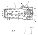
- Fig. 1 shows a hairdryer 1, which is designed as a hand-held device.
- This preferably has a plastic housing 2 and a handle 3.
- the housing 2 is approximately tubular formed and with an air inlet side 4 and a e.g. opposite air outlet side or air outlet opening 5 provided.
- air inlet side 4 and a e.g. opposite air outlet side or air outlet opening 5 provided.
- air outlet side is a guard 7 or another Protective cover attachable.
- the protective grid is preferably not made of plastic but Metallic, because a plastic protective grid more susceptible to electrical charges and electrical interference is.
- the housing 2 forms an air channel 8, in which a warm air stream for drying the hair flows.
- the ionization device comprises an electrode 12 with an electrode tip.
- the ionization device further consists of a high voltage source 11 - in particular a transformer - to form a preferably negative high voltage of preferably at least 2 kV and less than 6 kV, in particular less than 5 kV (per measured with gigaohm of the measuring instrument at the electrode tip).
- a measured Voltage of about 2.6 to 3.8 kV at the electrode tip is very advantageous, wherein the meter has a resistance of 1 Gigaohm.
- the transformer module becomes preferably fed with mains frequency.
- the open circuit voltage is below of 7 kV.
- a high-voltage generator which has a cascade connection, a piezo element or another generating element. At least the tension is but 1000V, which is already referred to as high voltage. To be favoured negative ions used to unload the hair.
- the internal resistance of the high voltage source is relatively high and is in particular about 5 to 20 megohms, especially about 10 megohms, so that a short circuit current of at most about 1.4 mA (e.g., 7kV / 5 megohms), preferably about 0.3 to 0.4 mA (e.g., 3 kV / 10 megohms) would be possible.
- This electricity is safe for people, so even in direct contact with the electrode 12 no danger.
- the generator can also be in the handle 3 in a bulge of the housing top, above or be integrated outside the Schuzzistromes or another location. Preferably But he is housed in an unheated area.
- the electrode 12 for ion ejection is via a cable 13, in particular a high-voltage cable, directly connected to the high voltage source.
- a cable 13 in particular a high-voltage cable, directly connected to the high voltage source.
- At the electrode 12 forms an electric field due to the high voltage.
- At a sharp area 18 takes place an increase in the electric field or an increase in the field strength (field concentration) instead of.
- the high voltage source 11 is, if necessary, switched on via a switch 13.
- the Voltage form is pulsed or as DC or AC voltage, e.g. as sinusoidal Voltage provided at 50 Hz.
- the cable 13 comprises at least one electrical insulation 14 and at least one electrical conductor 15 which is stripped at a free end, preferably 5 to 15 mm stripped.
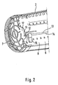
- the ionization electrode 12 is made in one piece from the electrical conductor 15 formed, as Fig. 2 and Fig. 4 illustrates.
- the free, stripped end of the cable is So the electrode 12 itself.
- the electrode 12 is directly and preferably only from the cable 13 held.
- the cable 13 is fixed exactly centric to slightly eccentric to the axis of the air duct. At most, the electrode 12 is spaced about 10 to 15 mm from the axis. Essentially she is still centric. The cable 13 is arranged axially to the air flow and leaves this alignment only in the vicinity of the handle 3, as shown in FIGS. 1 and 2 show.
- the cable 13 is on a guide and / or fastener, preferably attached from electrical insulation material.
- the cable 13 is at one Heating element carrier, in particular on one of a plurality of carrier plates 6, in particular a Mikanitnches or another Mikanitan extract, preferably with two or four or three or six plates 6, as shown in FIG. 3, attached.
- the heating element carrier enters or a plurality of heating elements, preferably consisting of helical heating wire 10, as Fig. 3 shows.
- the cable 13 is within the heating arrangement.
- the e.g. six plates 6 are preferably arranged in a star shape about the longitudinal axis.
- the cable 13 is further attached via at least one holding element 16, which in the vicinity of Electrode 12 and in the insulated conductor region is arranged.
- a second Retaining element 16 is present, which, however, is arranged closer to the handle 3.
- the plates 6 are recessed in the vicinity of the electrode 12 and thus form near the electrode a free space 17, wherein the electrode 12 is exposed in this space 17.
- the summit the electrode 12 is stored in the micanite cross or other micanite arrangement. Between the electrode tip and the carrier plates 6 or another carrier element is a distance of at least 5 mm, preferably at least 10mm available.
- the heating elements and the housing 2 form a heating tube.
- the conductor 15 is cut off at an angle, so that a tip 18 of preferably about 20 ° to 60 °, preferably formed about 30 ° to 45 ° becomes.
- the conductor 15 can also be cut off several times from several sides at an angle so that the tip 18 is in the middle of the conductor.
- the cut Tip arranged in a blow-out area of the hair dryer 1 and in particular in Heating channel integrated.
- the conductor cross section of the electrode 12 is stripped off, preferably about 0.8 to 2 mm.
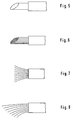
- the conductor 15 or the electrode 12 may comprise a single wire, as shown in FIG. 5 or consist of stranded wire with multiple wires, as Fig. 6 illustrates. It can also be used for education the electrode 12 is a multi-core cable with several insulated conductors or even a multi-wire stranded cable can be used (see Fig. 6-9).
- the conductor end may be spread radially outwards, as shown in FIG. 7 or e.g. cut obliquely and bent in a preferred direction, as shown in FIG. 8.
- the individual wire ends preferably made of strand, then lie one behind the other and next to each other. It is advantageous that a plurality of pointed areas 18a, 18b, 18c, etc. are present. Preferably the tips are essentially in the direction of action to the hair or air outlet of the Hair dryer directed and arranged in the blow-out area.
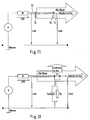
- the internal resistance Ri of the high voltage source hardly has Influence on the voltage at the Emittierstelle the electrode 12.
- the voltage Uah corresponds about the voltage Uaw, as shown in FIG. 11.
- parallel impedances or parallel capacitances Cp and resistors Rp which reduce the voltage Uaw by voltage division and thus worsening the ionization effect.
- This effect is especially at a high internal resistance of the generator Ri noticeable and is also of the voltage shape dependent.
- the capacitance Cp acts as a short circuit, whereby no ion emission in the air flow is possible.
- the electrode provided here can be a low-power generator with low voltage and / or lower power Electricity can be used.
- the tip formed by ultrasonic welding or by spark erosion is formed.
- the conductor end or the electrode can be squeezed, pulled or are formed from a predetermined breaking point, so that field concentration points arise.
Landscapes
- Cleaning And Drying Hair (AREA)
- Devices For Medical Bathing And Washing (AREA)
- Hair Curling (AREA)
Abstract
Description
- Fig. 1
- eine schematische Darstellung eines Haartrockners mit einer erfindungsgemäßen lonisationsvorrichtung,
- Fig. 2
- eine vergrößerte Darstellung eines Luftaustrittsbereiches des Haartrockners, in dem eine Elektrode vorhanden ist,
- Fig. 3
- einen Darstellung von Heizträgerplatten mit der Elektrode von einer Stirnseite aus gesehen,
- Fig. 4
- einen Darstellung der Elektrode,
- Fig. 5-9
- Varianten der Elektrode,
- Fig. 10
- einen Darstellung eines Schnittbereiches der Elektrode,
- Fig. 11
- ein Schaltbild der lonisationsvorrichtung, wobei ein großer horizontaler Pfeil den Gesamtluftfluss und ein kleiner Pfeil den effektiven lonenfluss darstellt, und
- Fig. 12
- ein weiteres Schaltbild der lonisationsvorrichtung mit einer parallelen Kapazität und einem parallelen Widerstand, wobei zusätzlich ein uneffektiver lonenfluss (nach oben gerichteter Pfeil) dargestellt ist.
Claims (24)
- Haarpflegegerät mit einer lonisationsvorrichtung zur Erzeugung einer Luftionisierung, mit einer Hochspannungsquelle (11), einem mit der Hochspannungsquelle (11) verbindbaren Kabel (13), der einen isolierten elektrischen Leiter (15) umfasst, wobei eine lonisationselektrode (12) an einem freien Ende des Leiters (15) zur Bildung eines elektrischen Feldes angeordnet ist und einen spitzen Bereich (18) umfasst, damit eine Feldkonzentration stattfindet, dadurch gekennzeichnet, dass die lonisationselektrode (12) einstückig aus dem elektrischen Leiter (15) gebildet ist.
- Haarpflegegerät nach Anspruch 1, dadurch gekennzeichnet, dass der spitze Bereich (18) der lonisationselektrode (12) durch Bearbeiten, insbesondere durch Abschneiden des elektrischen Leiters (15) gebildet ist.
- Haarpflegegerät nach Anspruch 2, dadurch gekennzeichnet, dass der spitze Bereich (18) durch einen Schräganschnitt eines Leiterendes am freien Ende des Leiters (15) gebildet ist.
- Haarpflegegerät nach einem der vorhergehenden Ansprüche, dadurch gekennzeichnet, dass der spitze Bereich (18) durch wenigstens einen Grat (21) gebildet ist, insbesondere eines Schräganschnitts.
- Haarpflegegerät nach Anspruch 3 oder 4, dadurch gekennzeichnet, dass der Schräganschnitt unter einem Winkel von 30° bis 70°, vorzugsweise etwa 45° bis 60° zur Leiterrichtung erfolgt und/oder derart erfolgt so dass eine Spitze von vorzugsweise etwa 20° bis 60°, vorzugsweise etwa 30° bis 45° gebildet wird.
- Haarpflegegerät nach einem der vorhergehenden Ansprüche, dadurch gekennzeichnet, dass mehrere spitze Bereiche (18) vorhanden sind.
- Haarpflegegerät nach einem der vorhergehenden Ansprüche, dadurch gekennzeichnet, dass das Kabel (13) ein Litzekabel mit Litzeadern und/oder ein mehradriges Kabel ist, das mehrere spitze Bereiche (18a - c) bildet.
- Haarpflegegerät nach Anspruch 7, dadurch gekennzeichnet, dass die Litze- und oder Aderenden voneinander beabstandet sind.
- Haarpflegegerät nach Anspruch 8, dadurch gekennzeichnet, dass die Litze- und oder Aderenden auseinander gefächert sind.
- Haarpflegegerät nach einem der vorhergehenden Ansprüche, dadurch gekennzeichnet, dass die lonisationselektrode (12) in einem Luftkanal (8) zur Erzeugung eines ionisierten Luftstromes angeordnet ist.
- Haarpflegegerät nach einem der vorhergehenden Ansprüche, dadurch gekennzeichnet, dass die lonisationselektrode (12) in Richtung des Luftkanals (8) verläuft.
- Haarpflegegerät nach Anspruch 10 oder 11, dadurch gekennzeichnet, dass die lonisationselektrode (12) im Wesentlichen etwa zentrisch im Luftkanal (8) angeordnet ist.
- Haarpflegegerät nach einem der Ansprüche 10 bis 12, dadurch gekennzeichnet, dass die lonisationelektrode (12) in einem beheizten oder heizbaren Bereich des Luftkanals (8) angeordnet ist.
- Haarpflegegerät nach einem der Ansprüche 10 bis 13, dadurch gekennzeichnet, dass das Kabel (13) zumindest teilweise innerhalb des Luftkanals (8), vorzugsweise etwa zentrisch im Luftkanal (8), geführt wird.
- Haarpflegegerät nach einem der vorhergehenden Ansprüche, dadurch gekennzeichnet, dass die Ionisationselektrode (12), insbesondere ohne zusätzliche Halteelemente, frei liegt.
- Haarpflegegerät nach einem der vorhergehenden Ansprüche, dadurch gekennzeichnet, dass die lonisationelektrode (12) in der Nähe einer Luftaustrittsöffnung (5) angeordnet ist.
- Haarpflegegerät nach einem der vorhergehenden Ansprüche, dadurch gekennzeichnet, dass das Kabel (13) durch mindestens eine Heizträgerplatte (6), insbesondere einer Mikanitanordnung befestigt ist, und insbesondere durch mindestens ein Halteelement (16) gehalten ist.
- Haarpflegegerät nach einem der vorhergehenden Ansprüche, dadurch gekennzeichnet, dass die lonisationselektrode (12) in einem Heizkanal, vorzugsweise einem Heizrohr integriert ist.
- Haarpflegegerät nach einem der vorhergehenden Ansprüche, dadurch gekennzeichnet, dass die Hochspannungsquelle (13) eine Leerlaufspannung von 2 kV bis 7 kV aufweist, wobei ihr Innenwiderstand vorzugsweise 5 - 20 Megaohm, insbesondere 10 Megaohm beträgt.
- Haarpflegegerät nach einem der vorhergehenden Ansprüche, dadurch gekennzeichnet, daß die Hochspannungsquelle (13) die Elektrode und der elektrische Leiter derart ausgebildet sind, daß an der Elektrode eine negative Hochspannung von kleiner 5 kV, gemessen an 1 Gigaohm des Meßgerätes, anliegt.
- Haarpflegegerät nach einem der vorhergehenden Ansprüche, dadurch gekennzeichnet, dass die Hochspannungsquelle (13) ein Transformator auf Induktionsbasis ist.
- Haartrockner, insbesondere Handhaartrockner mit einer lonisationsvorrichtung nach einem der vorhergehenden Ansprüche, wobei im Gehäuse zum Luftaustritt ein metallisches Gitter vorgesehen ist.
- Warmluft-Lockenstab mit einer lonisationsvorrichtung nach einem der vorhergehenden Ansprüche.
- Haarbürste mit einer lonisationsvorrichtung nach einem der vorhergehenden Ansprüche, wobei die Hochspannungsquelle batteriegespeist ist.
Priority Applications (1)
| Application Number | Priority Date | Filing Date | Title |
|---|---|---|---|
| PL04023317T PL1527709T3 (pl) | 2003-10-31 | 2004-09-30 | Urządzenie do pielęgnacji włosów z jonizatorem |
Applications Claiming Priority (2)
| Application Number | Priority Date | Filing Date | Title |
|---|---|---|---|
| DE10351265 | 2003-10-31 | ||
| DE10351265A DE10351265A1 (de) | 2003-10-31 | 2003-10-31 | Haarpflegegerät |
Publications (2)
| Publication Number | Publication Date |
|---|---|
| EP1527709A1 true EP1527709A1 (de) | 2005-05-04 |
| EP1527709B1 EP1527709B1 (de) | 2008-03-19 |
Family
ID=34399660
Family Applications (1)
| Application Number | Title | Priority Date | Filing Date |
|---|---|---|---|
| EP04023317A Expired - Lifetime EP1527709B1 (de) | 2003-10-31 | 2004-09-30 | Haarpflegegerät mit Ionisationsvorrichtung |
Country Status (5)
| Country | Link |
|---|---|
| EP (1) | EP1527709B1 (de) |
| AT (1) | ATE389337T1 (de) |
| DE (2) | DE10351265A1 (de) |
| ES (1) | ES2301909T3 (de) |
| PL (1) | PL1527709T3 (de) |
Cited By (6)
| Publication number | Priority date | Publication date | Assignee | Title |
|---|---|---|---|---|
| GB2411832A (en) * | 2004-03-09 | 2005-09-14 | Wik Far East Ltd | Hair curling device with an ion emitter |
| EP2138065A1 (de) * | 2008-06-26 | 2009-12-30 | Gamma S.P.A. | Ionisierungsvorrichtung, insbesondere für Heizwiderstände in Haartrocknern und ähnlichen Maschinen |
| US9986810B2 (en) | 2015-10-21 | 2018-06-05 | Dyson Technology Limited | Hand held appliance |
| US10021951B2 (en) | 2015-10-21 | 2018-07-17 | Dyson Technology Limited | Hand held appliance |
| US10085538B2 (en) | 2015-10-21 | 2018-10-02 | Dyson Technology Limited | Hand held appliance |
| WO2023180641A1 (fr) * | 2022-03-22 | 2023-09-28 | Jean-Daniel Mondin | Procédé de soins capillaires et appareil pour sa mise en oeuvre |
Families Citing this family (2)
| Publication number | Priority date | Publication date | Assignee | Title |
|---|---|---|---|---|
| DE102006024319A1 (de) | 2006-05-24 | 2007-11-29 | Braun Gmbh | Haarpflegegerät mit Ionisationsvorrichtung |
| US9982942B2 (en) | 2014-02-10 | 2018-05-29 | World Dryer Corporation | Dryer with universal voltage controller |
Citations (4)
| Publication number | Priority date | Publication date | Assignee | Title |
|---|---|---|---|---|
| US3997817A (en) * | 1975-05-21 | 1976-12-14 | Philip Edward Secker | Device for neutralizing the charge on statically-charged surfaces |
| US4352143A (en) * | 1980-05-27 | 1982-09-28 | Kenkichi Uno | Device for discharging static electricity and method of producing the same |
| FR2766338A1 (fr) * | 1997-07-22 | 1999-01-29 | Seb Sa | Accessoire de seche-cheveux destine a la neutralisation des charges electrostatiques des cheveux |
| DE20316899U1 (de) * | 2003-10-31 | 2004-02-12 | Braun Gmbh | Haarpflegegerät |
Family Cites Families (8)
| Publication number | Priority date | Publication date | Assignee | Title |
|---|---|---|---|---|
| DE1948197A1 (de) * | 1969-09-24 | 1971-04-01 | Harald Schulze | Vorrichtung zur Ableitung statischer Aufladung mittels Spitzenionisation |
| DE8430251U1 (de) * | 1984-10-15 | 1984-12-06 | Christofidis, Theoktiste, Chadwell Heath, Essex | Ionisierungsvorrichtung |
| US5612849A (en) * | 1994-12-30 | 1997-03-18 | Conair Corporation | Static eliminator for hair dryers |
| DE19603336A1 (de) * | 1996-01-31 | 1997-08-07 | Braun Ag | Verfahren und Vorrichtung zur Befestigung eines Gitters in einem Gehäuse insbesondere eines Haartrockners |
| DE29711062U1 (de) * | 1996-12-17 | 1997-09-25 | Almandinger, Markus, 52525 Heinsberg | Inhalationsgerät |
| DE19748067A1 (de) * | 1997-10-31 | 1999-05-12 | Braun Gmbh | Haarformgerät und Verfahren zum Formen der Haare |
| US6191930B1 (en) * | 1999-08-20 | 2001-02-20 | Igia Direct, Inc. | Ionizing hair dryer |
| KR100446050B1 (ko) * | 2001-06-14 | 2004-08-30 | 마츠시다 덴코 가부시키가이샤 | 헤어드라이어 |
-
2003
- 2003-10-31 DE DE10351265A patent/DE10351265A1/de not_active Withdrawn
-
2004
- 2004-09-30 ES ES04023317T patent/ES2301909T3/es not_active Expired - Lifetime
- 2004-09-30 DE DE502004006560T patent/DE502004006560D1/de not_active Expired - Lifetime
- 2004-09-30 EP EP04023317A patent/EP1527709B1/de not_active Expired - Lifetime
- 2004-09-30 PL PL04023317T patent/PL1527709T3/pl unknown
- 2004-09-30 AT AT04023317T patent/ATE389337T1/de not_active IP Right Cessation
Patent Citations (4)
| Publication number | Priority date | Publication date | Assignee | Title |
|---|---|---|---|---|
| US3997817A (en) * | 1975-05-21 | 1976-12-14 | Philip Edward Secker | Device for neutralizing the charge on statically-charged surfaces |
| US4352143A (en) * | 1980-05-27 | 1982-09-28 | Kenkichi Uno | Device for discharging static electricity and method of producing the same |
| FR2766338A1 (fr) * | 1997-07-22 | 1999-01-29 | Seb Sa | Accessoire de seche-cheveux destine a la neutralisation des charges electrostatiques des cheveux |
| DE20316899U1 (de) * | 2003-10-31 | 2004-02-12 | Braun Gmbh | Haarpflegegerät |
Cited By (8)
| Publication number | Priority date | Publication date | Assignee | Title |
|---|---|---|---|---|
| GB2411832A (en) * | 2004-03-09 | 2005-09-14 | Wik Far East Ltd | Hair curling device with an ion emitter |
| GB2411832B (en) * | 2004-03-09 | 2007-06-13 | Wik Far East Ltd | Application handling device for rolling hair curlers |
| EP2138065A1 (de) * | 2008-06-26 | 2009-12-30 | Gamma S.P.A. | Ionisierungsvorrichtung, insbesondere für Heizwiderstände in Haartrocknern und ähnlichen Maschinen |
| US9986810B2 (en) | 2015-10-21 | 2018-06-05 | Dyson Technology Limited | Hand held appliance |
| US10021951B2 (en) | 2015-10-21 | 2018-07-17 | Dyson Technology Limited | Hand held appliance |
| US10085538B2 (en) | 2015-10-21 | 2018-10-02 | Dyson Technology Limited | Hand held appliance |
| WO2023180641A1 (fr) * | 2022-03-22 | 2023-09-28 | Jean-Daniel Mondin | Procédé de soins capillaires et appareil pour sa mise en oeuvre |
| FR3133762A1 (fr) * | 2022-03-22 | 2023-09-29 | Jean-Daniel Mondin | Procédé de soins capillaires et appareil pour sa mise en œuvre |
Also Published As
| Publication number | Publication date |
|---|---|
| EP1527709B1 (de) | 2008-03-19 |
| ES2301909T3 (es) | 2008-07-01 |
| ATE389337T1 (de) | 2008-04-15 |
| DE10351265A1 (de) | 2005-06-23 |
| PL1527709T3 (pl) | 2008-08-29 |
| DE502004006560D1 (de) | 2008-04-30 |
Similar Documents
| Publication | Publication Date | Title |
|---|---|---|
| EP0986319B1 (de) | Epilationsgerät und epilationsverfahren | |
| DE102009045498B4 (de) | Verfahren und Vorrichtung zum Abtöten von Parasiten und deren Vorformen an filamentösem Gut | |
| DE602004004610T2 (de) | Ionengenerator Komponente, Ionengenerator Einheit und Ionengenerator Vorrichtung | |
| DD143995A5 (de) | Vorrichtung zur neutralisierung von elektrostatischen ladungen | |
| DE3610238C2 (de) | ||
| DE60129093T2 (de) | Ionengenerator und Haarbürste unter Verwendung desselben | |
| WO2009015833A1 (de) | Haarpflegegerät mit optimierter ionenabgabe | |
| DE3148380A1 (de) | Ionengenerator zur erzeugung einer luftstroemung | |
| EP1527709B1 (de) | Haarpflegegerät mit Ionisationsvorrichtung | |
| EP2037770B1 (de) | Haarpflegegerät mit ionisationsvorrichtung | |
| EP0920265B1 (de) | Elektrisch betriebenes gerät zur haarbehandlung | |
| EP2713807B1 (de) | Vorrichtung zur erzeugung elektrischer entladungen geringer energie, insbesondere zur bekämpfung von haarläusen | |
| DE2658287A1 (de) | Ionisierungsvorrichtung | |
| DE20316899U1 (de) | Haarpflegegerät | |
| DE102015000800B3 (de) | Emissionsspitzen-Anordnung und Verfahren zu deren Betrieb | |
| DE19634420C2 (de) | Elektrische Heizeinrichtung und elektrischer Haartrockner | |
| DE2307992A1 (de) | Warmluftfrisiergeraet | |
| EP2335332B1 (de) | Verfahren zum erzeugen eines ionenstromes bei einem haarform- oder -pflegegerät | |
| DE102021128964B3 (de) | Verfahren und Vorrichtung zur Erzeugung von Plasmen mit erhöhter Pulsenergie durch dielektrisch behinderte elektrische Entladungen | |
| DE2708117A1 (de) | Geraet zur erzeugung eines warmluftstrahls | |
| DE102019122930A1 (de) | Vorrichtung zur Erzeugung einer Gasentladung | |
| DE112020005530T5 (de) | Haarpflegevorrichtung | |
| CH574176A5 (de) | ||
| DE2408424A1 (de) | Stromabnahmevorrichtung fuer kabelverteiler | |
| CH652259A5 (en) | High-voltage supply device for a domestic or cosmetic appliance |
Legal Events
| Date | Code | Title | Description |
|---|---|---|---|
| PUAI | Public reference made under article 153(3) epc to a published international application that has entered the european phase |
Free format text: ORIGINAL CODE: 0009012 |
|
| 17P | Request for examination filed |
Effective date: 20040930 |
|
| AK | Designated contracting states |
Kind code of ref document: A1 Designated state(s): AT BE BG CH CY CZ DE DK EE ES FI FR GB GR HU IE IT LI LU MC NL PL PT RO SE SI SK TR |
|
| AX | Request for extension of the european patent |
Extension state: AL HR LT LV MK |
|
| AKX | Designation fees paid |
Designated state(s): AT BE BG CH CY CZ DE DK EE ES FI FR GB GR HU IE IT LI LU MC NL PL PT RO SE SI SK TR |
|
| 17Q | First examination report despatched |
Effective date: 20070515 |
|
| GRAP | Despatch of communication of intention to grant a patent |
Free format text: ORIGINAL CODE: EPIDOSNIGR1 |
|
| RIN1 | Information on inventor provided before grant (corrected) |
Inventor name: BOERGER, GEORG Inventor name: SMETANA, NORBERT Inventor name: SENG, JUERGEN |
|
| GRAS | Grant fee paid |
Free format text: ORIGINAL CODE: EPIDOSNIGR3 |
|
| GRAA | (expected) grant |
Free format text: ORIGINAL CODE: 0009210 |
|
| AK | Designated contracting states |
Kind code of ref document: B1 Designated state(s): AT BE BG CH CY CZ DE DK EE ES FI FR GB GR HU IE IT LI LU MC NL PL PT RO SE SI SK TR |
|
| REG | Reference to a national code |
Ref country code: GB Ref legal event code: FG4D Free format text: NOT ENGLISH |
|
| REG | Reference to a national code |
Ref country code: CH Ref legal event code: EP |
|
| REF | Corresponds to: |
Ref document number: 502004006560 Country of ref document: DE Date of ref document: 20080430 Kind code of ref document: P |
|
| REG | Reference to a national code |
Ref country code: IE Ref legal event code: FG4D Free format text: LANGUAGE OF EP DOCUMENT: GERMAN |
|
| REG | Reference to a national code |
Ref country code: ES Ref legal event code: FG2A Ref document number: 2301909 Country of ref document: ES Kind code of ref document: T3 |
|
| PG25 | Lapsed in a contracting state [announced via postgrant information from national office to epo] |
Ref country code: FI Free format text: LAPSE BECAUSE OF FAILURE TO SUBMIT A TRANSLATION OF THE DESCRIPTION OR TO PAY THE FEE WITHIN THE PRESCRIBED TIME-LIMIT Effective date: 20080319 |
|
| REG | Reference to a national code |
Ref country code: PL Ref legal event code: T3 |
|
| ET | Fr: translation filed | ||
| PG25 | Lapsed in a contracting state [announced via postgrant information from national office to epo] |
Ref country code: SI Free format text: LAPSE BECAUSE OF FAILURE TO SUBMIT A TRANSLATION OF THE DESCRIPTION OR TO PAY THE FEE WITHIN THE PRESCRIBED TIME-LIMIT Effective date: 20080319 |
|
| REG | Reference to a national code |
Ref country code: IE Ref legal event code: FD4D |
|
| PG25 | Lapsed in a contracting state [announced via postgrant information from national office to epo] |
Ref country code: CZ Free format text: LAPSE BECAUSE OF FAILURE TO SUBMIT A TRANSLATION OF THE DESCRIPTION OR TO PAY THE FEE WITHIN THE PRESCRIBED TIME-LIMIT Effective date: 20080319 Ref country code: SK Free format text: LAPSE BECAUSE OF FAILURE TO SUBMIT A TRANSLATION OF THE DESCRIPTION OR TO PAY THE FEE WITHIN THE PRESCRIBED TIME-LIMIT Effective date: 20080319 Ref country code: PT Free format text: LAPSE BECAUSE OF FAILURE TO SUBMIT A TRANSLATION OF THE DESCRIPTION OR TO PAY THE FEE WITHIN THE PRESCRIBED TIME-LIMIT Effective date: 20080826 Ref country code: SE Free format text: LAPSE BECAUSE OF FAILURE TO SUBMIT A TRANSLATION OF THE DESCRIPTION OR TO PAY THE FEE WITHIN THE PRESCRIBED TIME-LIMIT Effective date: 20080619 |
|
| PG25 | Lapsed in a contracting state [announced via postgrant information from national office to epo] |
Ref country code: RO Free format text: LAPSE BECAUSE OF FAILURE TO SUBMIT A TRANSLATION OF THE DESCRIPTION OR TO PAY THE FEE WITHIN THE PRESCRIBED TIME-LIMIT Effective date: 20080319 |
|
| PLBE | No opposition filed within time limit |
Free format text: ORIGINAL CODE: 0009261 |
|
| STAA | Information on the status of an ep patent application or granted ep patent |
Free format text: STATUS: NO OPPOSITION FILED WITHIN TIME LIMIT |
|
| PG25 | Lapsed in a contracting state [announced via postgrant information from national office to epo] |
Ref country code: IE Free format text: LAPSE BECAUSE OF FAILURE TO SUBMIT A TRANSLATION OF THE DESCRIPTION OR TO PAY THE FEE WITHIN THE PRESCRIBED TIME-LIMIT Effective date: 20080319 Ref country code: DK Free format text: LAPSE BECAUSE OF FAILURE TO SUBMIT A TRANSLATION OF THE DESCRIPTION OR TO PAY THE FEE WITHIN THE PRESCRIBED TIME-LIMIT Effective date: 20080319 |
|
| 26N | No opposition filed |
Effective date: 20081222 |
|
| BERE | Be: lapsed |
Owner name: BRAUN G.M.B.H. Effective date: 20080930 |
|
| PG25 | Lapsed in a contracting state [announced via postgrant information from national office to epo] |
Ref country code: EE Free format text: LAPSE BECAUSE OF FAILURE TO SUBMIT A TRANSLATION OF THE DESCRIPTION OR TO PAY THE FEE WITHIN THE PRESCRIBED TIME-LIMIT Effective date: 20080319 Ref country code: MC Free format text: LAPSE BECAUSE OF NON-PAYMENT OF DUE FEES Effective date: 20080930 Ref country code: BG Free format text: LAPSE BECAUSE OF FAILURE TO SUBMIT A TRANSLATION OF THE DESCRIPTION OR TO PAY THE FEE WITHIN THE PRESCRIBED TIME-LIMIT Effective date: 20080619 |
|
| REG | Reference to a national code |
Ref country code: CH Ref legal event code: PL |
|
| PG25 | Lapsed in a contracting state [announced via postgrant information from national office to epo] |
Ref country code: BE Free format text: LAPSE BECAUSE OF NON-PAYMENT OF DUE FEES Effective date: 20080930 |
|
| PG25 | Lapsed in a contracting state [announced via postgrant information from national office to epo] |
Ref country code: CY Free format text: LAPSE BECAUSE OF FAILURE TO SUBMIT A TRANSLATION OF THE DESCRIPTION OR TO PAY THE FEE WITHIN THE PRESCRIBED TIME-LIMIT Effective date: 20080319 |
|
| PG25 | Lapsed in a contracting state [announced via postgrant information from national office to epo] |
Ref country code: CH Free format text: LAPSE BECAUSE OF NON-PAYMENT OF DUE FEES Effective date: 20080930 Ref country code: LI Free format text: LAPSE BECAUSE OF NON-PAYMENT OF DUE FEES Effective date: 20080930 Ref country code: AT Free format text: LAPSE BECAUSE OF NON-PAYMENT OF DUE FEES Effective date: 20080930 |
|
| PG25 | Lapsed in a contracting state [announced via postgrant information from national office to epo] |
Ref country code: LU Free format text: LAPSE BECAUSE OF NON-PAYMENT OF DUE FEES Effective date: 20080930 Ref country code: HU Free format text: LAPSE BECAUSE OF FAILURE TO SUBMIT A TRANSLATION OF THE DESCRIPTION OR TO PAY THE FEE WITHIN THE PRESCRIBED TIME-LIMIT Effective date: 20080920 |
|
| PG25 | Lapsed in a contracting state [announced via postgrant information from national office to epo] |
Ref country code: GR Free format text: LAPSE BECAUSE OF FAILURE TO SUBMIT A TRANSLATION OF THE DESCRIPTION OR TO PAY THE FEE WITHIN THE PRESCRIBED TIME-LIMIT Effective date: 20080620 |
|
| REG | Reference to a national code |
Ref country code: FR Ref legal event code: PLFP Year of fee payment: 12 |
|
| REG | Reference to a national code |
Ref country code: FR Ref legal event code: PLFP Year of fee payment: 13 |
|
| REG | Reference to a national code |
Ref country code: FR Ref legal event code: PLFP Year of fee payment: 14 |
|
| PGFP | Annual fee paid to national office [announced via postgrant information from national office to epo] |
Ref country code: TR Payment date: 20170921 Year of fee payment: 14 Ref country code: PL Payment date: 20170817 Year of fee payment: 14 |
|
| REG | Reference to a national code |
Ref country code: FR Ref legal event code: PLFP Year of fee payment: 15 |
|
| PG25 | Lapsed in a contracting state [announced via postgrant information from national office to epo] |
Ref country code: PL Free format text: LAPSE BECAUSE OF NON-PAYMENT OF DUE FEES Effective date: 20180930 |
|
| PG25 | Lapsed in a contracting state [announced via postgrant information from national office to epo] |
Ref country code: TR Free format text: LAPSE BECAUSE OF NON-PAYMENT OF DUE FEES Effective date: 20180930 |
|
| PGFP | Annual fee paid to national office [announced via postgrant information from national office to epo] |
Ref country code: NL Payment date: 20220819 Year of fee payment: 19 |
|
| PGFP | Annual fee paid to national office [announced via postgrant information from national office to epo] |
Ref country code: IT Payment date: 20220811 Year of fee payment: 19 Ref country code: GB Payment date: 20220811 Year of fee payment: 19 |
|
| PGFP | Annual fee paid to national office [announced via postgrant information from national office to epo] |
Ref country code: FR Payment date: 20220808 Year of fee payment: 19 |
|
| PGFP | Annual fee paid to national office [announced via postgrant information from national office to epo] |
Ref country code: ES Payment date: 20221005 Year of fee payment: 19 |
|
| P01 | Opt-out of the competence of the unified patent court (upc) registered |
Effective date: 20230430 |
|
| PGFP | Annual fee paid to national office [announced via postgrant information from national office to epo] |
Ref country code: DE Payment date: 20230808 Year of fee payment: 20 |
|
| REG | Reference to a national code |
Ref country code: NL Ref legal event code: MM Effective date: 20231001 |
|
| GBPC | Gb: european patent ceased through non-payment of renewal fee |
Effective date: 20230930 |
|
| PG25 | Lapsed in a contracting state [announced via postgrant information from national office to epo] |
Ref country code: NL Free format text: LAPSE BECAUSE OF NON-PAYMENT OF DUE FEES Effective date: 20231001 |
|
| PG25 | Lapsed in a contracting state [announced via postgrant information from national office to epo] |
Ref country code: NL Free format text: LAPSE BECAUSE OF NON-PAYMENT OF DUE FEES Effective date: 20231001 |
|
| PG25 | Lapsed in a contracting state [announced via postgrant information from national office to epo] |
Ref country code: GB Free format text: LAPSE BECAUSE OF NON-PAYMENT OF DUE FEES Effective date: 20230930 |
|
| PG25 | Lapsed in a contracting state [announced via postgrant information from national office to epo] |
Ref country code: GB Free format text: LAPSE BECAUSE OF NON-PAYMENT OF DUE FEES Effective date: 20230930 Ref country code: FR Free format text: LAPSE BECAUSE OF NON-PAYMENT OF DUE FEES Effective date: 20230930 |
|
| REG | Reference to a national code |
Ref country code: DE Ref legal event code: R071 Ref document number: 502004006560 Country of ref document: DE |
|
| REG | Reference to a national code |
Ref country code: ES Ref legal event code: FD2A Effective date: 20241105 |
|
| PG25 | Lapsed in a contracting state [announced via postgrant information from national office to epo] |
Ref country code: IT Free format text: LAPSE BECAUSE OF NON-PAYMENT OF DUE FEES Effective date: 20230930 |
|
| PG25 | Lapsed in a contracting state [announced via postgrant information from national office to epo] |
Ref country code: IT Free format text: LAPSE BECAUSE OF NON-PAYMENT OF DUE FEES Effective date: 20230930 |
|
| PG25 | Lapsed in a contracting state [announced via postgrant information from national office to epo] |
Ref country code: ES Free format text: LAPSE BECAUSE OF NON-PAYMENT OF DUE FEES Effective date: 20231001 |
|
| PG25 | Lapsed in a contracting state [announced via postgrant information from national office to epo] |
Ref country code: ES Free format text: LAPSE BECAUSE OF NON-PAYMENT OF DUE FEES Effective date: 20231001 |