EP1527316B1 - Rollbandmass - Google Patents
Rollbandmass Download PDFInfo
- Publication number
- EP1527316B1 EP1527316B1 EP02755117A EP02755117A EP1527316B1 EP 1527316 B1 EP1527316 B1 EP 1527316B1 EP 02755117 A EP02755117 A EP 02755117A EP 02755117 A EP02755117 A EP 02755117A EP 1527316 B1 EP1527316 B1 EP 1527316B1
- Authority
- EP
- European Patent Office
- Prior art keywords
- switch
- tape measure
- braking
- push
- cam
- Prior art date
- Legal status (The legal status is an assumption and is not a legal conclusion. Google has not performed a legal analysis and makes no representation as to the accuracy of the status listed.)
- Expired - Lifetime
Links
- 239000000463 material Substances 0.000 claims description 7
- 230000008859 change Effects 0.000 claims description 5
- 210000003813 thumb Anatomy 0.000 claims description 3
- 238000006073 displacement reaction Methods 0.000 claims description 2
- 210000003811 finger Anatomy 0.000 claims description 2
- 230000007246 mechanism Effects 0.000 description 27
- 230000008901 benefit Effects 0.000 description 5
- 238000005259 measurement Methods 0.000 description 5
- 229920000642 polymer Polymers 0.000 description 3
- 239000004677 Nylon Substances 0.000 description 2
- DHKHKXVYLBGOIT-UHFFFAOYSA-N acetaldehyde Diethyl Acetal Natural products CCOC(C)OCC DHKHKXVYLBGOIT-UHFFFAOYSA-N 0.000 description 2
- 125000002777 acetyl group Chemical class [H]C([H])([H])C(*)=O 0.000 description 2
- 230000001419 dependent effect Effects 0.000 description 2
- 229920001971 elastomer Polymers 0.000 description 2
- 238000012986 modification Methods 0.000 description 2
- 230000004048 modification Effects 0.000 description 2
- 229920001778 nylon Polymers 0.000 description 2
- 239000004033 plastic Substances 0.000 description 2
- 229920003023 plastic Polymers 0.000 description 2
- 239000005060 rubber Substances 0.000 description 2
- 239000002250 absorbent Substances 0.000 description 1
- 230000009471 action Effects 0.000 description 1
- 239000011162 core material Substances 0.000 description 1
- 230000000694 effects Effects 0.000 description 1
- 210000005224 forefinger Anatomy 0.000 description 1
- 239000002783 friction material Substances 0.000 description 1
- 238000002347 injection Methods 0.000 description 1
- 239000007924 injection Substances 0.000 description 1
- 238000012423 maintenance Methods 0.000 description 1
- 238000004519 manufacturing process Methods 0.000 description 1
- 239000002991 molded plastic Substances 0.000 description 1
- 238000000465 moulding Methods 0.000 description 1
- 230000008092 positive effect Effects 0.000 description 1
- 239000007787 solid Substances 0.000 description 1
- 230000002459 sustained effect Effects 0.000 description 1
- 229920002725 thermoplastic elastomer Polymers 0.000 description 1
Images

Classifications
-
- G—PHYSICS
- G01—MEASURING; TESTING
- G01B—MEASURING LENGTH, THICKNESS OR SIMILAR LINEAR DIMENSIONS; MEASURING ANGLES; MEASURING AREAS; MEASURING IRREGULARITIES OF SURFACES OR CONTOURS
- G01B3/00—Measuring instruments characterised by the use of mechanical techniques
- G01B3/10—Measuring tapes
- G01B3/1005—Means for controlling winding or unwinding of tapes
- G01B3/1007—Means for locking
- G01B2003/1015—Means for locking engaging the tape in a direction transversal to the tape itself
-
- G—PHYSICS
- G01—MEASURING; TESTING
- G01B—MEASURING LENGTH, THICKNESS OR SIMILAR LINEAR DIMENSIONS; MEASURING ANGLES; MEASURING AREAS; MEASURING IRREGULARITIES OF SURFACES OR CONTOURS
- G01B3/00—Measuring instruments characterised by the use of mechanical techniques
- G01B3/10—Measuring tapes
- G01B3/1005—Means for controlling winding or unwinding of tapes
- G01B2003/1033—Means for activating the locking, braking or releasing of the tape, e.g. buttons
- G01B2003/1035—Means for activating the locking, braking or releasing of the tape, e.g. buttons by pivotal operation
-
- G—PHYSICS
- G01—MEASURING; TESTING
- G01B—MEASURING LENGTH, THICKNESS OR SIMILAR LINEAR DIMENSIONS; MEASURING ANGLES; MEASURING AREAS; MEASURING IRREGULARITIES OF SURFACES OR CONTOURS
- G01B3/00—Measuring instruments characterised by the use of mechanical techniques
- G01B3/10—Measuring tapes
- G01B3/1041—Measuring tapes characterised by casings
- G01B3/1046—Details of external structure thereof, e.g. shapes for ensuring firmer hold
Definitions
- the present invention relates to tape measures, and in particular to tape measures having a spooled measuring blade.
- Known tape measures include tape measures having a metallic measuring blade which is spooled within a casing.
- the blade is extendable from the casing by pulling its free end. When released, the blade is automatically retracted back into the casing.
- this retraction is due to a spring within the casing, for example a spring connected between the casing and a reel on which the blade spools.
- a brake is provided which can be operated to prevent the blade from retracting or from extending further.
- the brake can act on the reel to prevent spooling and/or unspooling of the blade.
- the brake can act directly on the blade to prevent movement with respect to the casing. In either case, the brake must exert a considerable force since the blade is usually immobilised by friction. In the case where the brake acts directly on the blade, the brake can press the blade against a portion of the casing.
- a brake is engageable by operation of a button or the like on or in the casing.
- it may be engageable by operation of a slider. In either case, the user normally must exert considerable force to engage and/or disengage the brake since the brake itself must exert considerable force to brake the blade.
- US-A-3220112 describes a tape measure having a brake mechanism operated by a switch that extends along the full length of the base of the tape measure case.
- the switch is pivoted at its centre and is biased by a spring to its locking position.
- the present invention provides a tape measure as set forth in claim 1.
- a pivotable switch (as opposed to a slider switch, for example) facilitates the engagement and disengagement of the braking means.
- the switch is pivotable about an axis in the middle third of the switch, one end of the switch may be designated as a braking means engagement end and the other end as a braking means disengagement end.
- pivot axis of the switch preferably intersects the body of the switch itself.
- this feature there are certain switch embodiments which do not necessarily require this feature.
- the axis about which the switch is pivotable lies approximately half way along the length of the switch.
- the leverage provided to the user by each of the ends of the switch is approximately the same. This is particularly advantageous if the braking mechanism requires approximately equal force magnitudes for engagement and disengagement.
- the axis about which the switch is pivotable lies in a position between approximately one third and one half of the way along the length of the switch. Since the distances between the ends of the switch and the pivot axis are not the same, the leverage provided to the user by each of the ends of the switch is not the same. This is particularly advantageous if the braking mechanism requires unequal force magnitudes for engagement compared to disengagement.
- the pivot axis lies closer to the disengagement end of the switch than to the engagement end, e.g. in the case where the engagement of the braking means requires a higher force than the disengagement of the braking means.
- the switch length is greater than twice the radius of the fully spooled measuring blade.
- the length of the switch determines its effectiveness, along with the position of the pivot axis, in acting as a lever to engage or disengage the brake. This is explained further below.
- the brake usually acts against the force of a spring (which typically acts to urge the blade back into its spooled configuration). Therefore, the effectiveness of the braking means may be judged (at least in part) by how well the brake prevents re-spooling of the blade.
- the class or size of spring used is dependent on the size of the tape measure, which in turn is dependent on the overall length of the blade.
- the shape of the blade (including its overall length) determines the radius of the fully spooled blade.
- the radius of the fully spooled blade also has an impact on the dimensions of the case. Therefore preferable ranges for the switch length can be defined in terms of the dimensions of the case.
- the switch length is greater than half or three-quarters of the length of the case (measured in a direction parallel to the direction in which the blade is drawable from the case).
- the switch length may be more than half or three-quarters of the length of the "footprint" of the tape measure. More preferably, the switch length is greater than half or three quarters of the maximum linear dimension of the case.
- the brake acts directly on the blade, it is usually situated at or close to an opening in the casing through which the blade is extendable. Furthermore, the button/slider for operation of the brake is usually located close to the brake to allow a simple mechanical linkage between the two. This location is inconvenient for the user since, during use of the tape measure, no part of a user's hand is normally located close to the opening.
- the button and slider may be combined as a single part. Therefore, for engagement/disengagement of the brake, a user must normally change grip or move his hand in order to operate the button or slider to engage and/or disengage the brake. This can lead to unwanted movement of the blade or casing, and can cause unnecessary strain on the user's hand.
- EP-A-393892 discloses a tape measure with a locking mechanism which is activated by a button located directly above an opening through which the tape is extendable.
- the blade is extendable from the casing in a forward direction.
- the opening is at a lower corner of the casing.
- the button is located on a top surface of the casing in a forward position.
- the locking mechanism is activated and deactivated by a user's finger or thumb.
- considerable force is required to operate the button, particularly to deactivate the locking mechanism, it may nevertheless be necessary for a user to change grip to operate the button.
- the invention provides an ergonomic shape to the switch and case which allows engagement and disengagement of the braking means without a change of grip required on the part of the user's hand.
- the switch is located at the top, e.g. at the top surface, of the case. In normal use, it is this part of the tape measure which is held by the user's hand, and so this location of the switch is typically most convenient.
- the braking means is a particularly important part of the tape measure, since the braking means determines the force with which the extended measuring blade is held in the extended position. This in turn affects the usefulness of the tape measure since a firm brake can assist the user in, e.g., ensuring consistent measurement readings during a series of measurements.
- a firm brake can assist the user in, e.g., ensuring consistent measurement readings during a series of measurements.
- This may be the case, for example, where the blade is extended to a particular length during a measurement and this length of blade is used to carry out a different, subsequent measurement. Any movement of the blade into or, more likely, out of the case may affect the subsequent measurement. Such movement may, for example, be caused by the user hooking the free end of the blade over the object to be measured. This can cause the blade to drag from the case.
- Known tape measures use a brake which comprises a wedge-type brake foot which is driven onto the blade to trap the blade between the brake foot and an inner surface of the case (a brake pad).
- a brake foot wedges are typically operated using sliding switches.
- the slider and button are combined in one moulding, the slider having a brake foot at the opposite end to the button.
- the slider rotates in a track and the brake foot acts a wedge trapping the blade between the brake foot and the brake pad on the case.
- the brake button is separate and acts on a brake spring/foot/wedge/member that applies the force to the blade. This can be achieved by rotational or a rocking pivot action.
- wedge braking mechanisms tend not to be able to apply enough force to the blade to give a strong frictional grip on the blade. Using only a mild force, it is usually possible to drag the blade from the case further, even when such a brake is applied.
- cam braking system In a cam braking system, a cam (in this case, a frictional engagement member which is mounted so that it can rotate about a fixed post into a locking position, or equivalent means) is rotated onto the blade in order to press it against an opposing surface, e.g. an inner surface of the case (brake pad).
- cam brakes are more efficient than directly-driven wedge brakes since a firmer frictional grip on the blade can be obtained using the cam.
- the cam requires rotating into position, and this in general requires a large force.
- a known tape measure of the cam braking type is manufactured by Fisco and called the Uni-Matic tape measure (product code UM).
- This tape measure has a cam brake which is operated using a rotatable lever which is directly connected to the cam.
- the lever is located on the side of the case of the tape measure. This is necessitated by the nature of the force which must be applied to rotate the cam into and out of position. However, the lever can be awkward to operate due to its location.
- the braking means includes a cam brake which is pivotable about an axis fixed with respect to the case, wherein the cam brake has a rotatable joint with a first end of a push-pull member for rotation of the cam between braking and non-braking positions.
- the push-pull member may, for example, be a rod.
- the second end of the push-pull member is moveable by operation of a pivotable switch.
- the second end of the push-pull member may, for example, be connected (typically rotatably, e.g. by a hinge) to one end of the pivotable switch.
- the cam brake can be engaged by the user pressing one end of the pivotable switch, rather than requiring the user to rotate directly a lever through the same angle as the cam.
- the push-pull member performs a pushing operation.
- the push-pull member performs a pulling operation. This can be actuated by a user pressing the opposite end of the pivotable switch compared to the end with which the push-pull member is connected.
- the pivotable switch can be located in a convenient position, and can be of an ergonomic size, shape and position.
- the user-operated means to engage/disengage the brake in this case, the switch) need not be fixedly connected to the cam.
- the tape measure includes spring means to urge the cam towards the braking position and/or towards the non-braking position.
- spring means may be provided to assist the user in applying or disengaging the brake.
- the spring means e.g. one or more, preferably one
- the spring means are arranged to bias the cam towards the braking position or the non-braking position, depending on the instantaneous position of the cam.
- the braking mechanism is bistable. That is, the braking mechanism is stable in two positions. Typically, the braking mechanism will be stable in a cam disengagement position and in a cam engagement position. It is usually possible to define an intermediate position between these positions, as described below. Typically, the intermediate position is closer to the cam engagement position than to the cam disengagement position.
- the spring means typically urges the braking mechanism towards the non-braking position. If the braking mechanism (e.g. the cam) is in a position between the intermediate position and the braking position, then the spring means typically urges the braking mechanism towards the braking position.
- the spring means is connected to the push-pull member.
- the spring means may be a leaf spring, a first end of which is fixed to the push-pull member.
- the second end (free end) of the leaf spring may be slidably engageable with a retaining surface. Movement of the push-pull member would then require movement of the second end of the leaf spring against the retaining surface.
- the retaining surface and the spring are typically arranged so that the intermediate point between the braking and non-braking positions of the braking mechanism corresponds to the maximum force applied to the push-pull member by the spring.
- the spring applies its maximum urging to the push-pull member.
- this corresponds to the maximum bend (or displacement) between the spring and the push-pull member which is possible in the range of movement of the braking mechanism.
- the push-pull member can be urged away from the intermediate point towards either the braking or non-braking position.
- the cam is formed of nylon.
- the cam is rotatably mounted about a rotation axis with respect to the casing.
- this joint is made via a hinge in a lever which is formed, e.g., integrally with the cam.
- the push-pull member must be made of a different material to the cam, since otherwise undesirable friction and noise might result.
- the push-pull member is formed of acetal (POM) or another material which has resilient properties in the sense that it has low creep, i.e. it has the ability to return to its original shape after sustained deflection.
- the spring means and the push-pull member are formed in one piece from the same material.
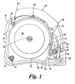
- the tape measure has a case 12 which is made from injection moulded plastics material, such as high impact ABS.
- the measure may also include outer features moulded into the case 12, such as shock-absorbent moulded pads 14,16, e.g. of rubber material (thermoelastic polymer).
- the case 12 may be manufactured in two parts (only one part being shown in Fig. 1 ), the tape measure being constructed by subsequently fitting the two parts together via connection points 18,20,22,36.
- the tape measure 10 includes a central mounting post 22. This post projects from a central region of the inner surface of the side wall 24 of the case.
- the spooled measuring blade (not shown) is rotatably mounted on post 22.
- Circle 26 provides an indication of the diameter of the fully spooled blade and an indication of the location of the spooled blade within the case.
- the blade In use, the blade is drawable from the tape measure via opening 28 in the case 12. Thus, the blade can be extended from the case in a direction roughly parallel to the lower surface 30 of the tape measure. The blade passes over blade engagement wall (brake pad) 32 on its way out of the case.
- Cam 34 Shown schematically in Fig. 1 is cam 34.
- Cam 34 is rotatably mounted on the casing at point 36, which is situated close to opening 28.
- cam 34 fits over a post projecting from the case at point 36 and is rotatable around and with respect to that post.
- Cam 34 also includes a frictional engagement surface 38 which rotates with the cam about point 36.
- the blade (not shown) can be gripped between the frictional engagement surface 38 and the blade engagement wall (brake pad) 32 when the cam is in the braking position (as shown in Fig. 1 ).
- the frictional engagement surface 38 is rotated up to about 90° clockwise about point 36 compared with the position shown in Fig. 1 .
- cam 34 has two frictional engagement surfaces, 38a and 38b. These are arranged so that each side of the measuring blade is gripped by the cam when the brake is engaged.
- Cam 34 also includes a lever arm 40 which projects from rotation centre 36.
- Lever arm 40 has a hole 42 (or a hole formed by opposing half-holes) for a hinge connection to a rigid push-pull member 44.
- a rigid push-pull member 44 For a hinge connection to a rigid push-pull member 44.
- Push-pull member 44 is attached at its other end, via a hinge 46, to a first end 48 of switch 50.
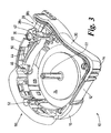
- Switch 50 is pivotable with respect to case 12 around pivot attachment 52, shown more clearly in Fig. 3 .
- the effect of a user pressing the second end 54 of the switch 50 downwards will be the upwards movement of the first end 48 of the switch, due to the pivoting nature of the switch. In turn, this upwards movement pulls up the push-pull member which rotates the cam in a clockwise direction, leading to the braking mechanism moving to the non-braking position.
- push-pull member 44 is not necessarily exactly straight. In particular, it can have a curvature in order to avoid interference with the spooled blade within the case, yet giving a compact tape measure design. However, it needs to be rigid enough not to deflect too much during use.
- the push-pull member 44 is cored out from both sides to remove some of the plastic material, to give it the form of an I-beam. This allows it to cool down quickly in the mould to reduce the production cycle time. If left solid, the plastic might be left semi-molten after ejection from the mould and the final dimensions therefore would be unpredictable.
- the switch 50 extends substantially full length along the upper face of the tape measure.
- the switch in particular gives the tape measure an ergonomic advantage because a user can apply the braking mechanism by pressing down the first end 48 of the switch using, e.g., his thumb or forefinger in normal use. Subsequently, the braking mechanism can be disengaged by pressing down the second end 54 of the switch.
- the second end 54 may be pressed using, e.g. the heel or palm of the user's hand. This is made possible by the length of the switch, and consequently the distance between the ends and the pivoting point 52.
- the usable area of the switch at each end to engage or disengage the brake is high.
- the arrangement of the switch at the top surface is more convenient for the user operating the tape measure.
- an advantage here over tape measures having the switch close to the opening in the case (here called opening 28) is that rapid re-spooling of the blade should not pose a safety threat to the hand operating the tape measure according to the preferred embodiment of the present invention.
- the switch is made from a rigid core material of ABS with a rubber or thermoplastic elastomer overmoulded covering to provide comfort and high impact resistance.
- the push-pull member and the spring (described below) are made from POM acetal.
- the cam is made from nylon.
- a spring 56 Formed integrally with the push-pull member 44 is a spring 56, connected to the push-pull member near the second end of the push-pull member, i.e. closer to the switch 50 than to the cam 34.
- the purpose of the spring is to assist the movement of the cam into the braking and non-braking positions.
- the spring biases the braking mechanism towards one of the extreme limits of travel possible for the braking mechanism with respect to the case 12.
- the free end 58 of the spring 56 is constrained to travel in a straight line by a surface of straight retaining wall 60. Therefore, when push-pull member 44 moves up or down, free end 58 of spring 56 slides against retaining wall 60.
- the hinge 42 connecting the first end of push-pull member 44 to the lever arm 40 must rotate with the lever arm when the push-pull member is moved up or down. Therefore the first end of the push-pull member must describe a similar path. This means that the first end of the push-pull member moves towards or away from the retaining wall 60 when the switch 50 is operated.
- the distance between the free end 58 of the spring 56 and the first end of the push-pull member varies with movement of the push-pull member.
- the spring exerts a non-zero force on the push-pull member, urging it in one direction or another.
- an intermediate point in the position of the braking mechanism at which the urging force exerted by the spring is a maximum. This is where the distance between the free end of the spring and the first end of the push-pull member is a maximum. This occurs when the line between points 42 and 36 makes a right angle with a line lying on the surface of the retaining wall 60.
- the push-pull member (and therefore the cam) is urged further on into the braking position.
- the push-pull member is urged back towards the non-braking position.
- the free end of the spring is typically rounded to facilitate an ejector in the mould tool. Ribs may be included on the retaining wall 60 to improve the feel and positive action of the brake.
- the provision of the spring assists the user in engaging and disengaging the brake. This improves the feel of the tape measure in giving a "click-on, click-off" feel to the braking mechanism. It can also help to avoid accidental engaging or disengaging of the brake since the spring provides a minimum resistance force which must be overcome to engage or disengage the brake.
Landscapes
- Physics & Mathematics (AREA)
- General Physics & Mathematics (AREA)
- Tape Measures (AREA)
- Investigating Or Analyzing Materials Using Thermal Means (AREA)
- Switches With Compound Operations (AREA)
- Materials For Medical Uses (AREA)
Claims (17)
- Rollbandmaß (10) mit einem Gehäuse (12), das ein aufgespultes Messblatt einfasst, Bremsmitteln (32, 34, 38) und einem Schwenkschalter (50), wobei das Blatt über eine Öffnung (28) aus dem Gehäuse (12) ausziehbar ist, wobei das Blatt bezüglich der Öffnung (28) über die Bremsmittel (32, 34, 38) bremsbar ist, die über den Schwenkschalter (50) zwischen Brems- und Nichtbremspositionen bistabil betriebsfähig sind, wobei der Schalter (50) eine Länge aufweist, die größer als das Zweifache des Radius des vollständig aufgespulten Messblatts ist, wobei der Schalter (50) derart angeordnet und bemessen ist, dass er im Gebrauch durch einen Benutzer zum Angreifen oder Lösen der Bremsmittel (32, 34, 38) mithilfe eines Daumens oder Fingers des Benutzers betriebsfähig ist und anschließend zum Lösen oder Angreifen der Bremsmittel (32, 34, 38) mithilfe des Handballens oder der Handfläche des Benutzers betriebsfähig ist, ohne den Griff zu ändern.
- Rollbandmaß (10) nach Anspruch 1, wobei der Schalter (50) um eine Achse im mittleren Drittel seiner Länge schwenkbar ist.
- Rollbandmaß (10) nach Anspruch 2, wobei die Achse, um die der Schalter (50) schwenkbar ist, ungefähr auf halbem Weg entlang der Länge des Schalters (50) liegt.
- Rollbandmaß (10) nach Anspruch 2, wobei die Achse, um die der Schalter (50) schwenkbar ist, in einer Position zwischen ungefähr einem Drittel und einer Hälfte des Wegs entlang der Länge des Schalters (50) liegt.
- Rollbandmaß (10) nach einem der Ansprüche 1 bis 4, wobei die Länge des Schalters (50) größer als die Hälfte oder drei Viertel der Länge des Gehäuses (12) ist.
- Rollbandmaß (10) nach einem der Ansprüche 1 bis 5, wobei die Länge des Schalters (50) mehr als die Hälfte oder drei Viertel der Länge der Standfläche des Rollbandmaßes (10) beträgt.
- Rollbandmaß (10) nach einem der Ansprüche 1 bis 6, wobei der Schalter (50) eine ergonomische Form aufweist, die das Angreifen und Lösen der Bremsmittel (32, 34, 38) ermöglicht, ohne eine Änderung des Handgriffs des Benutzers zu erfordern.
- Rollbandmaß (10) nach einem der Ansprüche 1 bis 7, wobei sich der Schalter (50) auf der Oberseite des Gehäuses (12) befindet.
- Rollbandmaß (10) nach einem der Ansprüche 1 bis 8, wobei die Bremsmittel (32, 34, 38) eine Nockenbremse (34) enthalten, die um eine Schwenkachse (36) eines Nockens (34) schwenkbar ist, der bezüglich des Gehäuses (12) befestigt ist, wobei die Nockenbremse (34) ein drehbares Gelenk mit einem ersten Ende eines Druck-Zug-Glieds (44) zum Drehen der Nockenbremse (34) zwischen Brems- und Nichtbremspositionen aufweist.
- Rollmaßband (10) nach Anspruch 9, wobei ein zweites Ende des Druck-Zug-Glieds (44) durch Betreiben des Schwenkschalters (50) verschiebbar ist.
- Rollmaßband (10) nach Anspruch 10, wobei das zweite Ende des Druck-Zug-Glieds (44) drehbar mit einem Ende des Schwenkschalters (50) verbunden ist.
- Rollbandmaß (10) nach einem der Ansprüche 9 bis 11, ferner enthaltend Federmittel (56) zum Drängen des Nockens (34) zur Bremsposition und/oder zur Nichtbremsposition hin.
- Rollmaßband (10) nach Anspruch 12, wobei das Federmittel (56) zum Vorspannen des Nockens (34) zur Bremsposition oder zur Nichtbremsposition hin, abhängig von der momentanen Position des Nockens (34), angeordnet ist.
- Rollmaßband (10) nach einem der Ansprüche 12 oder 13, wobei das Federmittel (56) mit dem Druck-Zug-Glied (44) verbunden ist.
- Rollmaßband (10) nach Anspruch 14, wobei das Federmittel (56) eine Blattfeder (56) ist, wobei ein erstes Ende davon an dem Druck-Zug-Glied (44) befestigt ist.
- Rollmaßband (10) nach Anspruch 15, wobei ein zweites, freies Ende der Blattfeder (56) zum Verändern der Verschiebung zwischen dem zweiten Ende der Feder (56) und dem Druck-Zug-Glied (44) gleitbar mit einer Rückhaltefläche (60) in Eingriff bringbar ist.
- Rollmaßband (10) nach einem der vorhergehenden Ansprüche 13 bis 15, wobei das Federmittel (56) und das Druck-Zug-Glied (44) einstückig aus demselben Material ausgebildet sind.
Applications Claiming Priority (1)
| Application Number | Priority Date | Filing Date | Title |
|---|---|---|---|
| PCT/GB2002/003529 WO2004013569A1 (en) | 2002-08-01 | 2002-08-01 | Tape measures |
Publications (2)
| Publication Number | Publication Date |
|---|---|
| EP1527316A1 EP1527316A1 (de) | 2005-05-04 |
| EP1527316B1 true EP1527316B1 (de) | 2011-02-16 |
Family
ID=31198369
Family Applications (1)
| Application Number | Title | Priority Date | Filing Date |
|---|---|---|---|
| EP02755117A Expired - Lifetime EP1527316B1 (de) | 2002-08-01 | 2002-08-01 | Rollbandmass |
Country Status (8)
| Country | Link |
|---|---|
| US (1) | US6854197B2 (de) |
| EP (1) | EP1527316B1 (de) |
| CN (1) | CN100380093C (de) |
| AT (1) | ATE498818T1 (de) |
| AU (1) | AU2002321415A1 (de) |
| DE (1) | DE60239230D1 (de) |
| ES (1) | ES2364129T3 (de) |
| WO (1) | WO2004013569A1 (de) |
Families Citing this family (18)
| Publication number | Priority date | Publication date | Assignee | Title |
|---|---|---|---|---|
| EP1527315B1 (de) * | 2002-08-01 | 2015-01-28 | Hultafors Group AB | Rollbandmasse mit schutzmitteln gegen stoss |
| US7024791B2 (en) * | 2004-01-12 | 2006-04-11 | Black & Decker Inc. | Tape measure with laser beam |
| JP4464908B2 (ja) * | 2005-11-17 | 2010-05-19 | 原度器株式会社 | 巻尺 |
| US20090064526A1 (en) * | 2007-09-06 | 2009-03-12 | Stuart David Farnworth | Tape measure |
| US8861185B2 (en) * | 2009-08-05 | 2014-10-14 | XIX Hendrik David Gideonse | Media player and peripheral devices therefore |
| CA2784047C (en) | 2011-07-29 | 2015-08-11 | Milwaukee Electric Tool Corporation | Tape measure |
| US9080849B2 (en) | 2011-07-29 | 2015-07-14 | Milwaukee Electric Tool Corporation | Tape measure |
| US8863399B2 (en) | 2011-08-26 | 2014-10-21 | Milwaukee Electric Tool Corporation | Tape measure |
| US9267778B2 (en) | 2012-01-19 | 2016-02-23 | Milwaukee Electric Tool Corporation | Tape measure |
| USD733597S1 (en) | 2012-07-30 | 2015-07-07 | Milwaukee Electric Tool Corporation | Tape measure |
| USD785475S1 (en) | 2015-12-10 | 2017-05-02 | Milwaukee Electric Tool Corporation | Tape measure |
| USD785476S1 (en) | 2015-12-10 | 2017-05-02 | Milwaukee Electric Tool Corporation | Tape measure |
| USD783429S1 (en) | 2016-01-07 | 2017-04-11 | Milwaukee Electric Tool Corporation | Tape measure |
| USD787347S1 (en) | 2016-01-07 | 2017-05-23 | Milwaukee Electric Tool Corporation | Tape measure |
| USD783430S1 (en) | 2016-01-07 | 2017-04-11 | Milwaukee Electric Tool Corporation | Tape measure |
| USD788611S1 (en) | 2016-06-01 | 2017-06-06 | Milwaukee Electric Tool Corporation | Tape measure |
| WO2020014578A1 (en) * | 2018-07-12 | 2020-01-16 | Apex Brands Inc. | Measuring tape with improved case durability |
| WO2023212195A1 (en) * | 2022-04-29 | 2023-11-02 | Stanley Black & Decker, Inc. | Tape measure housing with extended mouth and finger brake opening |
Family Cites Families (12)
| Publication number | Priority date | Publication date | Assignee | Title |
|---|---|---|---|---|
| DE1145803B (de) * | 1960-11-16 | 1963-03-21 | Erich Beck | Rollbandmass mit Rueckholfeder |
| FR81897E (fr) * | 1962-06-26 | 1963-11-22 | Quenot & Cie Ets | Appareil de mesure linéaire à ruban métallique |
| US3812588A (en) * | 1973-04-05 | 1974-05-28 | Waterbury Lock & Specialty Co | Tape measuring unit and locking and releasing device therefor |
| US4131244A (en) * | 1976-03-29 | 1978-12-26 | Stanley-Mabo S.A. | Tape measure brake |
| US4153996A (en) * | 1977-12-14 | 1979-05-15 | The Stanley Works | Coilable rule with combination blade lock and shock absorber mechanism |
| SE447678B (sv) * | 1985-04-16 | 1986-12-01 | Ljungberg Patent Ab T A | Anordning for lasning av foretredesvis for metning och merkning avsett langstreckt, i sin tverriktning kupat band i instellt lege |
| US4976048A (en) * | 1988-06-28 | 1990-12-11 | Cooper Industries, Inc. | Tape measure lock |
| US4927092A (en) * | 1988-06-30 | 1990-05-22 | Cooper Industries, Inc. | Tape measure locking system |
| US4938430A (en) * | 1988-08-24 | 1990-07-03 | Cooper Industries, Inc. | Tape measure lock |
| CA2014113A1 (en) * | 1989-04-17 | 1990-10-17 | David S. Chapin | Ergonomic tape measure housing |
| US6349482B1 (en) * | 2000-03-13 | 2002-02-26 | Cooper Brands, Inc. | Three position locking mechanism for a tape measure |
| CN2454754Y (zh) * | 2000-12-27 | 2001-10-17 | 宁波蓝达工量具有限公司 | 一种卷尺的制动装置 |
-
2002
- 2002-08-01 WO PCT/GB2002/003529 patent/WO2004013569A1/en not_active Ceased
- 2002-08-01 AT AT02755117T patent/ATE498818T1/de not_active IP Right Cessation
- 2002-08-01 DE DE60239230T patent/DE60239230D1/de not_active Expired - Lifetime
- 2002-08-01 EP EP02755117A patent/EP1527316B1/de not_active Expired - Lifetime
- 2002-08-01 ES ES02755117T patent/ES2364129T3/es not_active Expired - Lifetime
- 2002-08-01 AU AU2002321415A patent/AU2002321415A1/en not_active Abandoned
- 2002-08-01 CN CNB028294009A patent/CN100380093C/zh not_active Expired - Lifetime
-
2003
- 2003-07-25 US US10/626,606 patent/US6854197B2/en not_active Expired - Fee Related
Also Published As
| Publication number | Publication date |
|---|---|
| US20040163272A1 (en) | 2004-08-26 |
| WO2004013569A1 (en) | 2004-02-12 |
| ES2364129T3 (es) | 2011-08-25 |
| US6854197B2 (en) | 2005-02-15 |
| AU2002321415A1 (en) | 2004-02-23 |
| EP1527316A1 (de) | 2005-05-04 |
| ATE498818T1 (de) | 2011-03-15 |
| CN1639537A (zh) | 2005-07-13 |
| DE60239230D1 (de) | 2011-03-31 |
| CN100380093C (zh) | 2008-04-09 |
Similar Documents
| Publication | Publication Date | Title |
|---|---|---|
| EP1527316B1 (de) | Rollbandmass | |
| CA2796657C (en) | Tape measure with finger drag brake | |
| CA1193856A (en) | Power returnable coilable rule with improved blade locking assembly | |
| US5493781A (en) | Cutter | |
| US7421877B2 (en) | Electrohydraulic pressing device and method for operating the same | |
| US7703216B2 (en) | Automatic locking mechanism for a measuring tape device | |
| US6091035A (en) | Lockout mechanism for power tool | |
| US20170292821A1 (en) | Tape measure with flexible finger brake and related method | |
| EP1974177B1 (de) | Massbänder | |
| US10338626B2 (en) | Rolling hinge assembly | |
| US11604519B2 (en) | Input device | |
| US6032380A (en) | Tape measure structure with improved brake device | |
| CA1279338C (en) | Footwear scraper | |
| US20100299948A1 (en) | Tape measure | |
| US6256901B1 (en) | Measuring tape | |
| US5012057A (en) | Trigger switch | |
| US20070000347A1 (en) | Kickdown mechanism for pedal assembly | |
| WO2008053237A1 (en) | Brake mechanism for tape measures | |
| KR100911212B1 (ko) | 줄자 | |
| US20020026717A1 (en) | Electrical power tool with a rotatable working tool | |
| CN219265148U (zh) | 一种卷尺 | |
| CN221925173U (zh) | 一种便携式卡口传感器 | |
| CA2076453C (en) | Cutter | |
| KR20100040199A (ko) | 줄자 | |
| JPH03184501A (ja) | スポーツシューズ、特にモトクロス用のブーツのための締付装置、及び該締付装置を備えているブーツ |
Legal Events
| Date | Code | Title | Description |
|---|---|---|---|
| PUAI | Public reference made under article 153(3) epc to a published international application that has entered the european phase |
Free format text: ORIGINAL CODE: 0009012 |
|
| 17P | Request for examination filed |
Effective date: 20050224 |
|
| AK | Designated contracting states |
Kind code of ref document: A1 Designated state(s): AT BE BG CH CY CZ DE DK EE ES FI FR GB GR IE IT LI LU MC NL PT SE SK TR |
|
| AX | Request for extension of the european patent |
Extension state: AL LT LV MK RO SI |
|
| DAX | Request for extension of the european patent (deleted) | ||
| 17Q | First examination report despatched |
Effective date: 20060828 |
|
| GRAP | Despatch of communication of intention to grant a patent |
Free format text: ORIGINAL CODE: EPIDOSNIGR1 |
|
| GRAS | Grant fee paid |
Free format text: ORIGINAL CODE: EPIDOSNIGR3 |
|
| GRAA | (expected) grant |
Free format text: ORIGINAL CODE: 0009210 |
|
| AK | Designated contracting states |
Kind code of ref document: B1 Designated state(s): AT BE BG CH CY CZ DE DK EE ES FI FR GB GR IE IT LI LU MC NL PT SE SK TR |
|
| REG | Reference to a national code |
Ref country code: GB Ref legal event code: FG4D |
|
| REG | Reference to a national code |
Ref country code: CH Ref legal event code: EP |
|
| REG | Reference to a national code |
Ref country code: IE Ref legal event code: FG4D |
|
| REF | Corresponds to: |
Ref document number: 60239230 Country of ref document: DE Date of ref document: 20110331 Kind code of ref document: P |
|
| REG | Reference to a national code |
Ref country code: DE Ref legal event code: R096 Ref document number: 60239230 Country of ref document: DE Effective date: 20110331 |
|
| REG | Reference to a national code |
Ref country code: SE Ref legal event code: TRGR |
|
| REG | Reference to a national code |
Ref country code: NL Ref legal event code: VDEP Effective date: 20110216 |
|
| PG25 | Lapsed in a contracting state [announced via postgrant information from national office to epo] |
Ref country code: PT Free format text: LAPSE BECAUSE OF FAILURE TO SUBMIT A TRANSLATION OF THE DESCRIPTION OR TO PAY THE FEE WITHIN THE PRESCRIBED TIME-LIMIT Effective date: 20110616 Ref country code: GR Free format text: LAPSE BECAUSE OF FAILURE TO SUBMIT A TRANSLATION OF THE DESCRIPTION OR TO PAY THE FEE WITHIN THE PRESCRIBED TIME-LIMIT Effective date: 20110517 |
|
| REG | Reference to a national code |
Ref country code: ES Ref legal event code: FG2A Ref document number: 2364129 Country of ref document: ES Kind code of ref document: T3 Effective date: 20110825 |
|
| PG25 | Lapsed in a contracting state [announced via postgrant information from national office to epo] |
Ref country code: FI Free format text: LAPSE BECAUSE OF FAILURE TO SUBMIT A TRANSLATION OF THE DESCRIPTION OR TO PAY THE FEE WITHIN THE PRESCRIBED TIME-LIMIT Effective date: 20110216 Ref country code: BE Free format text: LAPSE BECAUSE OF FAILURE TO SUBMIT A TRANSLATION OF THE DESCRIPTION OR TO PAY THE FEE WITHIN THE PRESCRIBED TIME-LIMIT Effective date: 20110216 Ref country code: BG Free format text: LAPSE BECAUSE OF FAILURE TO SUBMIT A TRANSLATION OF THE DESCRIPTION OR TO PAY THE FEE WITHIN THE PRESCRIBED TIME-LIMIT Effective date: 20110516 Ref country code: NL Free format text: LAPSE BECAUSE OF FAILURE TO SUBMIT A TRANSLATION OF THE DESCRIPTION OR TO PAY THE FEE WITHIN THE PRESCRIBED TIME-LIMIT Effective date: 20110216 Ref country code: CY Free format text: LAPSE BECAUSE OF FAILURE TO SUBMIT A TRANSLATION OF THE DESCRIPTION OR TO PAY THE FEE WITHIN THE PRESCRIBED TIME-LIMIT Effective date: 20110216 Ref country code: AT Free format text: LAPSE BECAUSE OF FAILURE TO SUBMIT A TRANSLATION OF THE DESCRIPTION OR TO PAY THE FEE WITHIN THE PRESCRIBED TIME-LIMIT Effective date: 20110216 |
|
| PG25 | Lapsed in a contracting state [announced via postgrant information from national office to epo] |
Ref country code: EE Free format text: LAPSE BECAUSE OF FAILURE TO SUBMIT A TRANSLATION OF THE DESCRIPTION OR TO PAY THE FEE WITHIN THE PRESCRIBED TIME-LIMIT Effective date: 20110216 Ref country code: DK Free format text: LAPSE BECAUSE OF FAILURE TO SUBMIT A TRANSLATION OF THE DESCRIPTION OR TO PAY THE FEE WITHIN THE PRESCRIBED TIME-LIMIT Effective date: 20110216 |
|
| PG25 | Lapsed in a contracting state [announced via postgrant information from national office to epo] |
Ref country code: CZ Free format text: LAPSE BECAUSE OF FAILURE TO SUBMIT A TRANSLATION OF THE DESCRIPTION OR TO PAY THE FEE WITHIN THE PRESCRIBED TIME-LIMIT Effective date: 20110216 Ref country code: SK Free format text: LAPSE BECAUSE OF FAILURE TO SUBMIT A TRANSLATION OF THE DESCRIPTION OR TO PAY THE FEE WITHIN THE PRESCRIBED TIME-LIMIT Effective date: 20110216 |
|
| PLBE | No opposition filed within time limit |
Free format text: ORIGINAL CODE: 0009261 |
|
| STAA | Information on the status of an ep patent application or granted ep patent |
Free format text: STATUS: NO OPPOSITION FILED WITHIN TIME LIMIT |
|
| 26N | No opposition filed |
Effective date: 20111117 |
|
| REG | Reference to a national code |
Ref country code: DE Ref legal event code: R097 Ref document number: 60239230 Country of ref document: DE Effective date: 20111117 |
|
| PG25 | Lapsed in a contracting state [announced via postgrant information from national office to epo] |
Ref country code: MC Free format text: LAPSE BECAUSE OF NON-PAYMENT OF DUE FEES Effective date: 20110831 |
|
| REG | Reference to a national code |
Ref country code: CH Ref legal event code: PL |
|
| PG25 | Lapsed in a contracting state [announced via postgrant information from national office to epo] |
Ref country code: CH Free format text: LAPSE BECAUSE OF NON-PAYMENT OF DUE FEES Effective date: 20110831 Ref country code: LI Free format text: LAPSE BECAUSE OF NON-PAYMENT OF DUE FEES Effective date: 20110831 |
|
| REG | Reference to a national code |
Ref country code: FR Ref legal event code: ST Effective date: 20120430 |
|
| REG | Reference to a national code |
Ref country code: IE Ref legal event code: MM4A |
|
| PG25 | Lapsed in a contracting state [announced via postgrant information from national office to epo] |
Ref country code: IT Free format text: LAPSE BECAUSE OF FAILURE TO SUBMIT A TRANSLATION OF THE DESCRIPTION OR TO PAY THE FEE WITHIN THE PRESCRIBED TIME-LIMIT Effective date: 20110216 |
|
| PG25 | Lapsed in a contracting state [announced via postgrant information from national office to epo] |
Ref country code: IE Free format text: LAPSE BECAUSE OF NON-PAYMENT OF DUE FEES Effective date: 20110801 |
|
| PG25 | Lapsed in a contracting state [announced via postgrant information from national office to epo] |
Ref country code: FR Free format text: LAPSE BECAUSE OF NON-PAYMENT OF DUE FEES Effective date: 20110831 |
|
| PG25 | Lapsed in a contracting state [announced via postgrant information from national office to epo] |
Ref country code: LU Free format text: LAPSE BECAUSE OF NON-PAYMENT OF DUE FEES Effective date: 20110801 |
|
| PG25 | Lapsed in a contracting state [announced via postgrant information from national office to epo] |
Ref country code: TR Free format text: LAPSE BECAUSE OF FAILURE TO SUBMIT A TRANSLATION OF THE DESCRIPTION OR TO PAY THE FEE WITHIN THE PRESCRIBED TIME-LIMIT Effective date: 20110216 |
|
| PGFP | Annual fee paid to national office [announced via postgrant information from national office to epo] |
Ref country code: SE Payment date: 20210714 Year of fee payment: 20 Ref country code: DE Payment date: 20210715 Year of fee payment: 20 Ref country code: ES Payment date: 20210901 Year of fee payment: 20 Ref country code: GB Payment date: 20210716 Year of fee payment: 20 |
|
| REG | Reference to a national code |
Ref country code: DE Ref legal event code: R071 Ref document number: 60239230 Country of ref document: DE |
|
| REG | Reference to a national code |
Ref country code: GB Ref legal event code: PE20 Expiry date: 20220731 |
|
| REG | Reference to a national code |
Ref country code: ES Ref legal event code: FD2A Effective date: 20220826 |
|
| REG | Reference to a national code |
Ref country code: SE Ref legal event code: EUG |
|
| PG25 | Lapsed in a contracting state [announced via postgrant information from national office to epo] |
Ref country code: GB Free format text: LAPSE BECAUSE OF EXPIRATION OF PROTECTION Effective date: 20220731 Ref country code: ES Free format text: LAPSE BECAUSE OF EXPIRATION OF PROTECTION Effective date: 20220802 |