EP1527315B1 - Rollbandmasse mit schutzmitteln gegen stoss - Google Patents
Rollbandmasse mit schutzmitteln gegen stoss Download PDFInfo
- Publication number
- EP1527315B1 EP1527315B1 EP02747606.8A EP02747606A EP1527315B1 EP 1527315 B1 EP1527315 B1 EP 1527315B1 EP 02747606 A EP02747606 A EP 02747606A EP 1527315 B1 EP1527315 B1 EP 1527315B1
- Authority
- EP
- European Patent Office
- Prior art keywords
- tape measure
- blade
- case
- spooling device
- resilient
- Prior art date
- Legal status (The legal status is an assumption and is not a legal conclusion. Google has not performed a legal analysis and makes no representation as to the accuracy of the status listed.)
- Expired - Lifetime
Links
- 239000012858 resilient material Substances 0.000 claims description 12
- 238000006073 displacement reaction Methods 0.000 claims description 8
- 239000011359 shock absorbing material Substances 0.000 claims description 2
- 239000000463 material Substances 0.000 description 15
- 230000035939 shock Effects 0.000 description 7
- 239000004033 plastic Substances 0.000 description 6
- 229920003023 plastic Polymers 0.000 description 6
- 238000005452 bending Methods 0.000 description 5
- 238000010276 construction Methods 0.000 description 5
- 230000000694 effects Effects 0.000 description 5
- 238000001746 injection moulding Methods 0.000 description 4
- 230000003014 reinforcing effect Effects 0.000 description 4
- 238000000034 method Methods 0.000 description 3
- 238000000465 moulding Methods 0.000 description 3
- 238000010521 absorption reaction Methods 0.000 description 2
- 230000015572 biosynthetic process Effects 0.000 description 2
- 238000005336 cracking Methods 0.000 description 2
- 238000012986 modification Methods 0.000 description 2
- 230000004048 modification Effects 0.000 description 2
- 239000002991 molded plastic Substances 0.000 description 2
- 238000002835 absorbance Methods 0.000 description 1
- 230000002411 adverse Effects 0.000 description 1
- 230000000295 complement effect Effects 0.000 description 1
- 230000006835 compression Effects 0.000 description 1
- 238000007906 compression Methods 0.000 description 1
- 238000013016 damping Methods 0.000 description 1
- 238000013461 design Methods 0.000 description 1
- 230000001771 impaired effect Effects 0.000 description 1
- 238000010348 incorporation Methods 0.000 description 1
- 238000002347 injection Methods 0.000 description 1
- 239000007924 injection Substances 0.000 description 1
- 238000012423 maintenance Methods 0.000 description 1
- 238000004519 manufacturing process Methods 0.000 description 1
- 239000002184 metal Substances 0.000 description 1
- 239000007769 metal material Substances 0.000 description 1
- 230000002265 prevention Effects 0.000 description 1
- 238000007493 shaping process Methods 0.000 description 1
Images


Classifications
-
- G—PHYSICS
- G01—MEASURING; TESTING
- G01B—MEASURING LENGTH, THICKNESS OR SIMILAR LINEAR DIMENSIONS; MEASURING ANGLES; MEASURING AREAS; MEASURING IRREGULARITIES OF SURFACES OR CONTOURS
- G01B3/00—Measuring instruments characterised by the use of mechanical techniques
- G01B3/10—Measuring tapes
- G01B3/1005—Means for controlling winding or unwinding of tapes
-
- B—PERFORMING OPERATIONS; TRANSPORTING
- B29—WORKING OF PLASTICS; WORKING OF SUBSTANCES IN A PLASTIC STATE IN GENERAL
- B29C—SHAPING OR JOINING OF PLASTICS; SHAPING OF MATERIAL IN A PLASTIC STATE, NOT OTHERWISE PROVIDED FOR; AFTER-TREATMENT OF THE SHAPED PRODUCTS, e.g. REPAIRING
- B29C45/00—Injection moulding, i.e. forcing the required volume of moulding material through a nozzle into a closed mould; Apparatus therefor
- B29C45/16—Making multilayered or multicoloured articles
-
- G—PHYSICS
- G01—MEASURING; TESTING
- G01B—MEASURING LENGTH, THICKNESS OR SIMILAR LINEAR DIMENSIONS; MEASURING ANGLES; MEASURING AREAS; MEASURING IRREGULARITIES OF SURFACES OR CONTOURS
- G01B3/00—Measuring instruments characterised by the use of mechanical techniques
- G01B3/10—Measuring tapes
- G01B3/1041—Measuring tapes characterised by casings
- G01B3/1043—Details of internal structure thereof, e.g. means for coupling separately moulded casing halves
Definitions
- the present invention relates to tape measures, and in particular to tape measures having a spooled measuring blade.
- Known tape measures include tape measures having a measuring blade which is spooled within a casing.
- the blade is extendable from the casing by pulling its free end. When released, the blade is automatically retracted back into the casing.
- this retraction is due to a spring within the casing, for example a spring connected between the casing and a reel on which the blade spools.
- the casing is typically made from moulded plastics material. This allows the casing to be relatively lightweight and easy to handle.
- the moulding operation also allows the incorporation of detailed functional shapes into the casing in a single forming step.
- the blade of the measure is metallic.
- the blade must be strong and inextensible.
- it should also be stiff. This is particularly the case where the blade should be able to extend from the blade and hold itself in an approximately straight configuration without support at its distal end (the end furthest from the casing).
- this desirable feature is achieved using a relatively thin blade which, when pulled longitudinally straight from the casing, has a transversely curved character. It is this transverse curvature which acts to maintain the blade in an approximately straight longitudinal configuration.
- the spring which acts to recoil the blade back into the casing after the blade has been extended from the casing.
- the spring is usually made from metal and so is dense and therefore heavy.
- the blade is usually spooled, within the casing, on a spool or other rotatable mounting.
- the blade is therefore rotatably mounted within the casing, for example a reel or spool may be rotatably mounted on a post within the casing in order to define an axis of rotation for the reel or spool.
- the spring is attached between the post and the blade, so that when the blade is unspooled, the spring is tightened to provide a return force on the blade.
- Tape measures are often subjected to rough handling.
- tape measures are often dropped, e.g. from ladders. Drops onto relatively hard surfaces can be catastrophic for the tape measure. This is usually due to a combination of the plastics casing and the heavy blade. Since most of the mass of the whole tape measure is concentrated in the blade, during an impact on the casing, the blade is likely to move relative to the casing. Often, the result of this is damage to the case. More specifically, the post on which the blade is rotatably mounted usually either breaks or breaks away from the casing. This renders the tape measure inoperative or seriously impaired.
- US-A-34115461 , US-A-3437281 and US-A-3114515 all described tape measures with blades spooled on a drum and include a spring between the spooled blade and the case of the tape measure for braking movement of the drum.
- the present invention provides: a tape measure as set forth in claim 1.
- the resilient means can provide impact shock protection to the tape measure by, to some extent, mechanically insulating the mass of the blade from the casing.
- the resilient means preferably does not adversely affect the rotation of the spooled blade, i.e. it preferably does not affect the way in which the blade is extended from the casing for use.
- "displacement" means linear (as opposed to rotational) movement of the whole spooled blade.
- the whole blade can be considered to have two parts at any particular time: the part which is spooled within the casing (the spooled blade) and the part (if any) which is extended from the casing (the extended blade). In the present case, it is the spooled blade which is of concern, since it is the inertia of this part which can lead to damage of the tape measure.
- the resilient means can be placed in two distinct locations.
- the spooled blade may be rotatable with respect to the resilient means.
- the resilient means may be fixed with respect to the casing.
- the resilient means may be located between the casing and an axle element, for example.
- the axle element may be a mounting element on which the spooled blade is rotatable.
- it may be a post, pin, lug or plurality of lugs about which the spooled blade (or, more usually, the means on which the blade is spooled) is rotatable.
- the axle element does not rotate with respect to the casing. It is the axle element which is usually prone to breakage during an impact, so the resilient means acts to cushion the shock transferred to the axle element by the combination of the impact on the casing and the inertia of the spooled blade.
- the resilient member may be a bush or cup holding one end of the axle element with respect to a casing wall. There may be a corresponding resilient member located at the other end of the axle element with respect to an opposing casing wall.
- the resilient member may be formed by injection moulding of, e.g. rubber.
- the injection moulding of this or similar resilient material may be performed within the same tool as the injection moulding of the material for the casing.
- the resilient member may be formed in one piece with another resilient part attached to the casing, such as an external pad formed on the outer surface of the casing. This is discussed in more detail below with respect to a method of forming the tape measure.
- the resilient member can be the axle element itself, or part of the axle element. This eliminates the need for a separate axle element about which the spooled blade is to be rotatable.
- the axle element must be relatively stiff to provide a firm rotatable mounting position for the spooled blade. It should also be resilient and/or tough enough to withstand impact on the casing.
- the mounting means for the spooled blade is the means by which the axle element is attached to the casing, e.g. by a complementary shape in the casing allowing a friction fit.
- the resilient means may be rotatable with the spooled blade with respect to the casing.
- the resilient means when the casing has an axle element (or axle elements) about which the spooled blade is rotatable, the resilient means is also rotatable with respect to the axle element.
- the mounting means preferably includes a spooling device.
- This may be a rotatable frame on which or within which the blade can be spooled.
- the spooling device may be a reel or a drum.
- the spooling device may include side members which act to guide the blade during spooling and unspooling. The side members rotate with the spooled blade and can act to prevent the blade from abrading or touching the inner surface of the casing.
- the side members need not be connected to each other. They may each rotate about the axle element or elements. This construction is advantageous since the absence of a connection between the side members allows the spring to be attached easily between the blade and an anchor point fixed with respect to the casing (e.g. the axle element or post). This construction may also allow the spring more freedom of movement, i.e. allow fuller coiling and partial uncoiling of the spring.
- the spooled blade is typically located on an outer portion of the spooling device.
- the spring is typically located at an inner porting of the spooling device. Since the greater proportion the mass of the tape measure is due to the blade, the spooled blade on the spooling device has significant inertia which must be managed during an impact on the casing.
- the resilient member may be formed in the spooling device. Preferably, it is located between the outer portion of the spooling device and the axle element.
- the resilient means may be formed at the inner portion of one or both of the side members.
- Each disc typically has a bearing surface for bearing on the axle element(s) for rotation of the side member and hence rotation of the spooled blade.
- the resilient member should be located between the bearing surface and the outer portion of the spooling device or disc.
- the resilient member may be of a resilient material such as rubber.
- the resilient member may owe its resilience more to its structure than to its material.
- the resilient member is a connecting element which connects the outer portion of the spooling device to the bearing surface of the spooling device.
- the connecting element is typically shaped so that at least a part has a transverse component of force acting to bend it under a force acting radially between the bearing surface and the outer portion.
- "Radial" implies that the spooling device has circular symmetry, which is often true.
- a radial force is usually one which acts in a plane containing the outer portion of the spooling device and the bearing surface and which is substantially directed to intersect the axis of rotation of the spooling device.
- the resilient member is a series of connecting elements disposed around the bearing surface.
- the resilient member may be a spoke or a series of spokes arranged between the outer portion and the bearing surface of the disc or spooling device.
- the resilient member may be a strut, series of struts or a network of struts arranged between the outer portion and the bearing surface of the disc or spooling device. The resilience then comes from deformation (e.g. bending) of the spokes or struts.
- the resilient member should allow the bearing surface of the spooling device to move relative to the outer portion of the spooling device, but urge against such movement.
- Particularly preferred embodiments use non-linear struts or spokes, e.g. curved struts or spokes which can deform more easily than straight struts or spokes.
- the struts or spokes should not extend in a straight line the whole distance from the bearing surface to the outer portion of the spooling device. Therefore, any straight-line force acting between the bearing surface and the outer portion of the spooling device should act to bend at least a part of the spokes or struts (e.g. that part which does not coincide with the straight-line force).
- the connection path from the outer portion to the bearing surface via the spokes or struts is preferably non-linear.
- the shape of the spokes or struts can be selected according to the resilience required from the arrangement.
- the spokes or struts can form a spiral shape from the outer portion towards the bearing surface. They can be of S-shape, Z-shape, W-shape, V-shape, U-shape, C-shape, L-shape, dog-leg shape, concertina-shape, or combinations thereof.
- the resilient means may include a combination of spokes and struts arranged so that a path from the outer portion of the spooling device form a dog-leg along at least one spoke and at least one strut. Preferably, this arrangement is repeated for the whole resilient means.
- a "spoke” can be a connection element which is arranged generally radially (but not necessarily in a straight line) from the outer portion of the spooling device towards the bearing surface.
- a “strut” can be a connection element which is arranged generally circumferentially (but not necessarily along the arc of a circle or in a straight line) between the outer portion of the spooling device and the bearing surface.
- the gaps between adjacent spokes/struts may be filled with a resilient or shock-absorbing material, e.g. rubber. This can be used to tune the spring-back properties of the spooling device.
- the tape measure may include a spooling device on which the blade is mounted, the spooled measuring blade and the spooling device being rotatable with respect to the case about a rotation axis; and stop means located to abut against cooperating means on the spooling device on displacement of the spooling device with respect to the case.
- the stop means is located to abut against an outer surface of the spooling device.
- the spooling device is rotatably mounted within the casing via one or more axle elements, as described with respect to the first aspect.
- the stop means is preferably located so that the displacement of the spooling device (and hence substantially the displacement of the spooled blade) with respect to the casing is stopped or urged against at a displacement less than that required to cause failure or damage to the axle element.
- the stop means may be a step, protrusion or recess formed in the inner surface of a side wall of the casing.
- the step or protrusion may extend substantially all the way (e.g. circumferentially) around the casing.
- a corresponding step, protrusion or recess may be formed on the inner surface of an opposing side wall of the casing, this corresponding stop means being provided to abut against another, corresponding part of the spooling device.
- the stop member is an annular stop ring connected to the casing and extending adjacent to the spooling device.
- the stop member is an annular stop ring connected to the casing and extending around an outer abutment surface of the spooling device.
- the contact is preferably low-friction. This can be assisted by making the contacting surfaces of dissimilar materials.
- the stop member may be of a resilient material. This helps shock-absorption and can avoid damage to the spooling device and/or the casing.
- the stop member may be formed of a relatively non-resilient material, e.g. it may be formed of the same material as the casing (typically relatively hard-wearing plastics material).
- the invention deals mainly with the reduction or prevention of damage to the inner components of the tape measure, in particular the spooling device and the rotational assembly (e.g. axle element).
- the inventors have also investigated the damage which an impact can impart to the casing of a tape measure.
- the casings of modern tape measures are usually made from plastics materials due to the ease of formation of the complex shapes required for the casing by, e.g. injection moulding techniques.
- the casing must be relatively stiff to retain its overall shape and to avoid interference with the blade. A consequence of this is that the casing is often quite brittle and prone to breakage during impact.
- tape measures which have overjackets formed of resilient material. That is, a jacket is formed around the tape measure after the tape measure has been assembled, or the tape measure is inserted into a jacket after assembly of the tape measure.
- the jackets are typically provided for the purpose of improving the grip provided to a user. If made from resilient material, they have a further effect which is a shock-protection effect.
- overjackets provided by these known tape measures are bulky, In particular, since they are fitted to the tape measure, they must have lateral walls to grip the tape measure. These lateral walls make the whole object relatively thick and bulky to handle.
- Some embodiments of the present invention address the shock protection of the casing by providing resilient means, e.g. pads, at selected impact-vulnerable locations in the casing.
- a resilient pad or means allows the casing to be protected from impact at a vulnerable place, but allows the whole tape measure to retain the overall outward shape of the casing, and can reduce the overall thickness of the tape measure with respect to a corresponding tape measure held in an overjacket.
- Particularly vulnerable locations on the outer surface of the casing are the tape mouth (the opening in the casing from which the measuring blade is drawable), the switch (typically for engaging and disengaging a brake for controlling the blade) and the corners of the case.
- the resilient means may be formed by moulding-in resilient material into corresponding recesses formed in the casing. In the case of resilient pads, these may be anchored into the casing by suitable shaping of the recesses.
- Moulding-in of resilient pads in this way allows intimate connection of the resilient pads to the casing. This makes the pads secure and removes the need for an overjacket to provide shock protection.
- the resilient means in the case where the resilient means does not rotate with respect to the casing, it can be formed by moulding-in during casing formation.
- the resilient means may be formed as one piece with a resilient moulding (e.g. a pad) formed on the outer surface of the case. In that case, an interconnection between the pad and the resilient means is provided through the casing.
- the pad may be provided as a label-carrying surface of the casing.
- the invention provides a tape measure which can withstand an impact without significantly affecting its performance, e.g. without cracking or denting the casing and/or without cracking or permanently deforming the spooling device or the axle element(s).
- a tape measure according to the invention can withstand a drop of 3, 5 or even 10 metres onto a hard surface such as concrete.
- Fig. 1 shows a known spooling disc 10.
- the disc has an outer portion 12 with an outer surface 14.
- the measuring blade of a tape measure (not shown) is held between two opposing spooling discs 10 (only one is shown in Fig. 1 ).
- the tape measure is supported on a step (not shown) on each spooling disc, the step defining the interface between the outer portion of the disc and the inner portion 16 of the disc.
- the step is on the opposite face to the face illustrated.
- the inner portion 16 terminates towards the centre of the disc at a bearing surface 18. In use, bearing surface 18 rotates with respect to an axle (not shown) in the tape measure (not shown).
- inner portion 16 is of thin-walled parts 20 and reinforcing spokes 22 and reinforcing rings 24. This construction is aimed at giving a strong and stiff inner portion with little or no excess material used, for economy of material and weight.
- the spring is located between the inner portions of adjacent spooling discs.
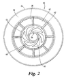
- Fig. 2 shows a spooling disc 30 according to an embodiment of the invention.
- Disc 30 has an outer portion 32 with an outer surface 34 and an inner portion 36.
- the central part of the inner portion 36 terminates in a bearing surface 38 for rotatably moving against an axle (not shown) of a tape measure (not shown).
- the inner portion 36 has spokes 42 extending in straight, radial lines towards the centre of the disc. Between the spokes 42 are thin walls 40. The spokes 42 extend from the outer portion 32 and terminate at reinforcing ring 44. Between the reinforcing ring 44 and bearing surface 38 are curved spokes 46. In this embodiment, curved spokes 46 together form a spiral pattern centred on the centre of the disc 30. Between the curved spokes 46 are gaps 48 which are empty. However, in other embodiments, these gaps may be filled with resilient material such as rubber, in order to tune the resilience of the inner portion of the disc as a whole.
- the curved spokes form a resilient means between the bearing surface and the outer portion of the disc. Therefore, the outer portion can move, to some extent, with respect to the bearing surface. Since the outer portion bears the weight (and inertia) of the spooled blade, this movement can distribute the effect of an impact to the tape measure over time. This can have the effect of damping the movement of the bearing surface with respect to the case, and therefore avoiding damage to the axle of the tape measure.
- a curved spoke flexes since the force of the impact has at least a component which is transverse to the direction of the curved spoke. It is this flexing which allows the outer portion 32 of the disc to move with respect to the bearing surface 38.
- the inner portion design shown in Fig. 2 is relatively stiff, since for each spoke which bends, other spokes must also deform in order to allow the outer portion 32 to move with respect to the bearing surface 38. In particular, those spokes which are roughly parallel to the direction of the force are urged to compress or extend by the force. Since the spokes are quite resistant to compression or extension, these spokes tend to make the disc relatively stiff.
- Fig. 2 The disc of Fig. 2 is also shown in perspective in Fig. 4.
- Fig. 4 shows the opposing side of the disc to that shown in Fig. 3 .
- Fig. 4 shows that the gaps 40 between adjacent spokes in Figs. 2 and 3 are filled by thin walls.
- the surface 52 shown in Fig. 4 faces the spring in the spooling device. Therefore, the spring (not shown) is located between opposing surfaces 52 of opposing discs.
- step 50 which defines the interface between the inner and outer portions of the disc. In use, the spooled blade is supported by this step, between opposing discs in the spooling device.
- Fig. 5 shows another embodiment of a disc for a spooling device.
- the spokes 60,62 are S-shaped.
- the spokes can be considered to be individual spring elements. Each is able to extend, compress or flex. Therefore, if a radial (with respect to the disc) force acts to compress spoke 60, that same force acts to shear spoke 62.
- the S-shape of spokes 60 and 62 allow the spokes to accommodate either type of deformation. Therefore, the presence of spoke 62 will not severely impair the ability of spoke 60 to compress or extend, and vice versa.
- This construction of the inner portion generally makes the disc more resilient (i.e. less stiff) than the disc shown in Figs. 2 to 4 .
- Fig. 6 shows another embodiment of a disc for a spooling device. Again, features similar to the embodiment shown in Figs. 2 to 4 will not be described again.
- a series of concentric ring members 80,82,84 is formed in the inner portion of the disc. Between the first ring 80 and the second ring 82 are formed straight spokes 86,88,90,92,94. Between the second ring and the third ring are formed straight spokes 96,98,100,102,104. None of the spokes 96-104 are colinear with any of spokes 86-94. That is, in drawing a line of connection between the first ring 80 and the third ring 84, the line is not straight.
- such lines of connection are all dog-legs, involving some travel along the second ring 82.
- the force bends the second ring in the region between its connection between spokes 100 and 102. It is this bending which allows the inner portion of the disc to absorb resiliently the impact.
- the movement of the third ring 84 relative to the outer portion of the disc is accommodated by bending of the spokes 90,104 and, to some extent, 102.
- a similar (and slightly less stiff) configuration can be made using interconnecting struts between spokes 86-94 and spokes 96-104.
- the interconnecting struts replace the second ring 82, and the shape change of the ring can be accommodated by bending of the struts in the same way as the bending of the second ring 82 accommodates the shape change in Fig. 6 .
- Fig. 7 shows another embodiment of the invention.
- the case 100 is formed from injection moulded plastics material.
- One disc 102 of a spooling device is mounted within the case 100 on a centre post 124.
- the centre post acts as an axle about which the spooling disc 102 (and the remainder of the spooling device which is not shown) is rotatable.
- the centre post has a split configuration with a mouth 106 for receiving one end of a spring of the spooling device.
- the centre post 124 has a resilient (e.g. rubber) bush 108 interposed between itself and the disc 102.
- the bush 108 allows the disc 102 to move with respect to the centre post 124.
- the disc 102 (which carries the spooled blade on step 110) is subjected to the inertia of the spooled blade. Movement of the disc without damage to the blade is accommodated by deformation of the resilient bush 108.
- the bush 108 may be formed by mounding-in of rubber material during moulding of the casing.
- the case 100 has, at its outer surface, resilient pads 112,114 which are moulded into vulnerable locations in the case. Furthermore, the rocker switch 116 of the tape measure case has at least one moulded in resilient pad 118 on its outer surface. These pads 112,114,116 provide shock absorption to the tape measure during an impact. Other parts of the tape measure may be protected by similar resilient mould-ins, e.g. the tape mouth area 120.
- Fig. 8 shows another tape measure (not covered by the claims).
- a cross-section of a tape measure is illustrated, taken though the centre of the tape measure and showing the centre post 124 and side walls 130 and 132.
- Fig. 8 does not show the spring or the spooled blade. However, it does show two opposed spooling discs 134,136.
- Spooling disc 136 is rotatably mounted on the root 138 of the centre post 124. Centre post 124 and root 138 are formed in one piece with side wall 132. Centre post 124 is received by locating collar 140 which is formed in one piece with side wall 130.
- Spooling disc 134 is rotatably mounted on locating collar 140.
- Spooling disc 134 had an annular groove 142 formed in its outer surface (i.e. the surface facing away from the opposing spooling disc). Annular groove 142 cooperates with annular retaining ring 144 which projects inwardly from the inner surface of the side wall 130. In use, i.e. on rotation of spooling disc 134, annular groove 142 moves along the annular retaining ring 144. Displacement of the spooling disc 134 in relation to the collar 140 is prevented by the retaining ring 144, i.e. by abutment of the surface of the groove 142 with the surface of the retaining ring 144.
- Spooling disc 136 has a similar arrangement.
- the retaining ring could also be located at a greater radius from the axis of rotation of the spooling disc 134, e.g. instead of the retaining ring cooperating with an annular groove in the disc, it could cooperate with the end surface 146 of the disc.
- the retaining ring 144 can be formed of a resilient material, allowing it to absorb shock from the impact.
- This resilient ring can be formed by moulding-in, as described above.
Landscapes
- Physics & Mathematics (AREA)
- General Physics & Mathematics (AREA)
- Engineering & Computer Science (AREA)
- Manufacturing & Machinery (AREA)
- Mechanical Engineering (AREA)
- Tape Measures (AREA)
Claims (15)
- Maßband, aufweisend:ein aufgespultes Messblatt, das über Anbringungsmittel (30, 102) innerhalb eines Gehäuses (100) angebracht ist, wobei das aufgespulte Messblatt bezüglich des Gehäuses (100) um eine Drehachse drehbar ist; undein elastisches Mittel (46, 60, 62, 86 - 104, 108), das im Anbringungsmittel (30, 102) zwischen dem aufgespulten Blatt und dem Gehäuse (100) eingelegt ist, wobei das elastische Mittel (46, 60, 62, 86 - 104, 108) Verschiebung des aufgespulten Blatts bezüglich des Gehäuses (100) in einer radial zur Drehachse verlaufenden Richtung ermöglicht, jedoch dagegen drängt.
- Maßband nach Anspruch 1, wobei das aufgespulte Blatt bezüglich des elastischen Mittels (46, 60, 62, 86 - 104, 108) drehbar ist.
- Maßband nach Anspruch 2, wobei das elastische Mittel (46, 60, 62, 86 - 104, 108) zwischen dem Gehäuse (100) und einem Achsenelement (124) eingelegt ist, das bezüglich des Gehäuses (100) starr ist.
- Maßband nach einem der Ansprüche 2 oder 3, wobei das elastische Mittel eine Buchse oder Pfanne (108) ist.
- Maßband nach Anspruch 1, wobei das Anbringungsmittel (30, 102) eine Spulvorrichtung (30) enthält und das elastische Mittel (46, 60, 62, 86 - 104) mit der Spulvorrichtung (30) bezüglich des Gehäuses (100) drehbar ist.
- Maßband nach Anspruch 5, wobei die Spulvorrichtung ein Seitenglied (30) aufweist, das zum Führen des Blatts während des Aufspulens und Abspulens wirkt, wobei das elastische Mittel (46, 60, 62, 86 - 104) im Seitenglied (30) ausgebildet ist.
- Maßband nach einem der Ansprüche 5 oder 6, wobei sich das aufgespulte Blatt an einem äußeren Abschnitt (32) der Spulvorrichtung befindet.
- Maßband nach Anspruch 7, wobei das elastische Mittel (46, 60, 62, 86 - 104) in der Spulvorrichtung ausgebildet ist und sich zwischen dem äußeren Abschnitt (32) der Spulvorrichtung und einer Lagerfläche (38) der Spulvorrichtung befindet.
- Maßband nach Anspruch 8, wobei das elastische Mittel (46, 60, 62, 86 - 104) ein Verbindungselement (36) ist, das den äußeren Abschnitt (32) der Spulvorrichtung mit der Lagerfläche (38) der Spulvorrichtung verbindet, wobei das Verbindungselement (36) derart geformt ist, dass zumindest ein Teil eine quer verlaufende Kraftkomponente aufweist, die zum Biegen desselben unter einer Kraft wirkt, welche radial zwischen der Lagerfläche (38) und dem äußeren Abschnitt (32) wirkt.
- Maßband nach Anspruch 9, wobei das elastische Mittel eine Reihe von Verbindungselementen (46, 60, 62, 86 - 104) ist, die um die Lagerfläche (38) herum angeordnet sind.
- Maßband nach Anspruch 10, wobei die Verbindungselemente (46, 60, 62, 86 - 104) eine Spiralform vom äußeren Abschnitt (32) zur Lagerfläche (38) hin ausbilden oder aus S-Form, Z-Form, W-Form, V-Form, U-Form, C-Form, L-Form, Gegenlaufform, Ziehharmonikaform oder Kombinationen davon ausgewählt sind.
- Maßband nach einem der Ansprüche 10 oder 11, wobei Spalte zwischen benachbarten Verbindungselementen (46, 60, 62, 86 - 104) mit einem elastischen oder stoßdämpfenden Material gefüllt sind.
- Maßband nach einem der Ansprüche 1 bis 12 mit einer Spulvorrichtung (134, 136), auf der das Blatt angebracht ist, und einem Anschlagmittel (144), das zum Anstoßen an Zusammenwirkungsmittel (142) an der Spulvorrichtung (134) bei Verschiebung der Spulvorrichtung (134) bezüglich des Gehäuses (100) in einer radial zur Drehachse verlaufenden Richtung angeordnet ist, wobei das Anschlagmittel (144) eine Stufe, ein Vorsprung oder eine Aussparung ist, die/der in der Innenfläche einer Seitenwand des Gehäuses (100) ausgebildet ist, welche im Wesentlichen ganz um das Gehäuse (100) herum verläuft, und das entsprechende Zusammenwirkungsmittel (142) an der Spulvorrichtung jeweils eine Stufe, eine Aussparung bzw. ein Vorsprung ist.
- Maßband nach Anspruch 13, wobei das Anschlagglied ein kranzförmiger Anschlagring (142) ist, der mit dem Gehäuse (100) verbunden oder darin ausgebildet ist und der Spulvorrichtung (134) benachbart verläuft.
- Maßband nach einem der Ansprüche 1 bis 14 mit elastischen Polstern (112, 114), die wahlweise an der Außenfläche des Gehäuses (100) angeordnet sind, wobei der Standort oder die Standorte der elastischen Polster (112, 114) gemäß Stoßanfälligkeit des Standorts oder der Standorte ausgewählt sind, wobei die elastischen Polster (112, 114) durch Einformen von elastischem Material in entsprechende Aussparungen ausgebildet sind, welche im Gehäuse (100) ausgebildet sind.
Applications Claiming Priority (1)
| Application Number | Priority Date | Filing Date | Title |
|---|---|---|---|
| PCT/GB2002/003557 WO2004013570A1 (en) | 2002-08-01 | 2002-08-01 | Tape measures with impact protection |
Publications (2)
| Publication Number | Publication Date |
|---|---|
| EP1527315A1 EP1527315A1 (de) | 2005-05-04 |
| EP1527315B1 true EP1527315B1 (de) | 2015-01-28 |
Family
ID=31198370
Family Applications (1)
| Application Number | Title | Priority Date | Filing Date |
|---|---|---|---|
| EP02747606.8A Expired - Lifetime EP1527315B1 (de) | 2002-08-01 | 2002-08-01 | Rollbandmasse mit schutzmitteln gegen stoss |
Country Status (5)
| Country | Link |
|---|---|
| US (1) | US7100300B2 (de) |
| EP (1) | EP1527315B1 (de) |
| CN (1) | CN1310009C (de) |
| AU (1) | AU2002317994A1 (de) |
| WO (1) | WO2004013570A1 (de) |
Families Citing this family (5)
| Publication number | Priority date | Publication date | Assignee | Title |
|---|---|---|---|---|
| GB0422760D0 (en) * | 2004-10-13 | 2004-11-17 | Fisco Tools Ltd | Tape measure housing |
| USD553027S1 (en) * | 2005-10-07 | 2007-10-16 | Actuant Corporation | Winder |
| US8476567B2 (en) * | 2008-09-22 | 2013-07-02 | Semiconductor Components Industries, Llc | Active pixel with precharging circuit |
| US8793890B2 (en) | 2011-04-13 | 2014-08-05 | Stanley Black & Decker, Inc. | Tape rule housing |
| CN103434078A (zh) * | 2013-08-09 | 2013-12-11 | 杭州万峰实业有限公司 | 一种工具外壳及其制造方法 |
Family Cites Families (16)
| Publication number | Priority date | Publication date | Assignee | Title |
|---|---|---|---|---|
| US1465067A (en) * | 1922-08-10 | 1923-08-14 | William S Tothill | Amusement apparatus |
| US3114515A (en) * | 1962-09-28 | 1963-12-17 | Porter Co H K | Flexible tape rule |
| FR90857E (fr) * | 1966-07-11 | 1968-03-01 | Quenot & Cie Sarl | Perfectionnements aux instruments de mesure linéaire |
| US3415461A (en) * | 1965-10-23 | 1968-12-10 | Cooper Ind Inc | Measuring tape construction |
| US3443316A (en) * | 1966-12-19 | 1969-05-13 | Porter Co Inc H K | Tape rule lock |
| US4286387A (en) * | 1979-03-02 | 1981-09-01 | The Stanley Works | Coilable rule casing |
| EP0074007A3 (de) * | 1981-08-27 | 1984-01-18 | Howard Wall Limited | Federbelastetes Rollbandmass |
| KR890005501Y1 (ko) * | 1986-12-23 | 1989-08-21 | 주식회사 한국도량 | 권척의 줄자 정지장치 |
| JPH0383974U (de) * | 1989-12-19 | 1991-08-26 | ||
| US5791581A (en) * | 1996-11-27 | 1998-08-11 | The Stanley Works | Tape rule blade hook shock absorbers |
| US6182916B1 (en) * | 1999-11-12 | 2001-02-06 | Index Measuring Tape Co., Ltd. | Measuring tape dispenser with an impact buffer housing and tentative tape halting means |
| JP3774617B2 (ja) * | 2000-07-17 | 2006-05-17 | 株式会社ケイディエス | 巻尺 |
| US6470590B1 (en) * | 2000-09-13 | 2002-10-29 | Shih-Lin Lee | Brake device for a tape rule |
| US6581296B2 (en) * | 2000-10-19 | 2003-06-24 | Felix C. Ponce | Tape measure with laser beam |
| US20030233762A1 (en) * | 2002-06-19 | 2003-12-25 | Blackman William C. | Tape measure housing with grip element |
| AU2002321415A1 (en) * | 2002-08-01 | 2004-02-23 | Fisco Tools Limited | Tape measures |
-
2002
- 2002-08-01 AU AU2002317994A patent/AU2002317994A1/en not_active Abandoned
- 2002-08-01 EP EP02747606.8A patent/EP1527315B1/de not_active Expired - Lifetime
- 2002-08-01 US US10/522,685 patent/US7100300B2/en not_active Expired - Lifetime
- 2002-08-01 CN CNB028295366A patent/CN1310009C/zh not_active Expired - Lifetime
- 2002-08-01 WO PCT/GB2002/003557 patent/WO2004013570A1/en not_active Ceased
Also Published As
| Publication number | Publication date |
|---|---|
| CN1662787A (zh) | 2005-08-31 |
| EP1527315A1 (de) | 2005-05-04 |
| CN1310009C (zh) | 2007-04-11 |
| US7100300B2 (en) | 2006-09-05 |
| WO2004013570A1 (en) | 2004-02-12 |
| US20050235515A1 (en) | 2005-10-27 |
| AU2002317994A1 (en) | 2004-02-23 |
Similar Documents
| Publication | Publication Date | Title |
|---|---|---|
| CA2503257C (en) | Disc brake pad with friction elements particularly to be employed in the railway field | |
| EP1527315B1 (de) | Rollbandmasse mit schutzmitteln gegen stoss | |
| US12344346B2 (en) | Cycle suspension with travel indicator | |
| CA1257181A (en) | Integrally molded hammer with separated head and handle cores | |
| JP4502221B2 (ja) | 球面と弾性部材を用いた車輪及びその車輪を備えたキャスタ | |
| JPS62251530A (ja) | 棒状部品のダストカバー | |
| FI77604B (fi) | Faergbandskassett med svaengbar styrning i ett stycke. | |
| US6373157B1 (en) | Stator | |
| US4055314A (en) | Wire pay-off cap assembly for wire spools | |
| EP3899306B1 (de) | Anordnung aus mindestens zwei bremsbelägen und mindestens einer feder | |
| EP2063325B1 (de) | Mechanisches Uhrwerk | |
| CA2123306C (en) | A friction rock stabilizer | |
| US6170328B1 (en) | Lever gauge with hinged arms | |
| GB2137165A (en) | Magnetic tape cassette | |
| US4574922A (en) | Pin assembly for a caliper disc brake | |
| JPH04502804A (ja) | スポット型ディスクブレーキ及び関連のハウジング及びブレーキシュー用の押えばね | |
| CN222991827U (zh) | 一种具有防护结构的液压油缸 | |
| KR20230148170A (ko) | 상쇄적 토션 스프링 힘을 이용한 고-이격도 벨트 텐셔너 | |
| US3985162A (en) | Knotting gear | |
| EP0561280B1 (de) | Schnurwickelmechanismus | |
| JP2869026B2 (ja) | 架空線用テンションバランサ | |
| JPH0921440A (ja) | 横変形防止用コイルバネ | |
| JPH1137308A (ja) | バタフライバルブの弁体 | |
| CN220608238U (zh) | 清洁机器人 | |
| CN214946007U (zh) | 一种铸造流水线上的缓冲装置 |
Legal Events
| Date | Code | Title | Description |
|---|---|---|---|
| PUAI | Public reference made under article 153(3) epc to a published international application that has entered the european phase |
Free format text: ORIGINAL CODE: 0009012 |
|
| 17P | Request for examination filed |
Effective date: 20050224 |
|
| AK | Designated contracting states |
Kind code of ref document: A1 Designated state(s): AT BE BG CH CY CZ DE DK EE ES FI FR GB GR IE IT LI LU MC NL PT SE SK TR |
|
| AX | Request for extension of the european patent |
Extension state: AL LT LV MK RO SI |
|
| DAX | Request for extension of the european patent (deleted) | ||
| 17Q | First examination report despatched |
Effective date: 20060828 |
|
| GRAP | Despatch of communication of intention to grant a patent |
Free format text: ORIGINAL CODE: EPIDOSNIGR1 |
|
| INTG | Intention to grant announced |
Effective date: 20140820 |
|
| RIN1 | Information on inventor provided before grant (corrected) |
Inventor name: LEE, BARRY, HOWARD Inventor name: KNIGHT, J. A. M. |
|
| GRAS | Grant fee paid |
Free format text: ORIGINAL CODE: EPIDOSNIGR3 |
|
| GRAA | (expected) grant |
Free format text: ORIGINAL CODE: 0009210 |
|
| RAP1 | Party data changed (applicant data changed or rights of an application transferred) |
Owner name: HULTAFORS GROUP AB |
|
| AK | Designated contracting states |
Kind code of ref document: B1 Designated state(s): AT BE BG CH CY CZ DE DK EE ES FI FR GB GR IE IT LI LU MC NL PT SE SK TR |
|
| REG | Reference to a national code |
Ref country code: GB Ref legal event code: FG4D |
|
| REG | Reference to a national code |
Ref country code: CH Ref legal event code: EP |
|
| REG | Reference to a national code |
Ref country code: IE Ref legal event code: FG4D |
|
| REG | Reference to a national code |
Ref country code: DE Ref legal event code: R096 Ref document number: 60246947 Country of ref document: DE Effective date: 20150312 |
|
| REG | Reference to a national code |
Ref country code: AT Ref legal event code: REF Ref document number: 708412 Country of ref document: AT Kind code of ref document: T Effective date: 20150315 |
|
| REG | Reference to a national code |
Ref country code: SE Ref legal event code: TRGR |
|
| REG | Reference to a national code |
Ref country code: AT Ref legal event code: MK05 Ref document number: 708412 Country of ref document: AT Kind code of ref document: T Effective date: 20150128 |
|
| REG | Reference to a national code |
Ref country code: NL Ref legal event code: VDEP Effective date: 20150128 |
|
| PG25 | Lapsed in a contracting state [announced via postgrant information from national office to epo] |
Ref country code: BG Free format text: LAPSE BECAUSE OF FAILURE TO SUBMIT A TRANSLATION OF THE DESCRIPTION OR TO PAY THE FEE WITHIN THE PRESCRIBED TIME-LIMIT Effective date: 20150428 Ref country code: ES Free format text: LAPSE BECAUSE OF FAILURE TO SUBMIT A TRANSLATION OF THE DESCRIPTION OR TO PAY THE FEE WITHIN THE PRESCRIBED TIME-LIMIT Effective date: 20150128 Ref country code: FI Free format text: LAPSE BECAUSE OF FAILURE TO SUBMIT A TRANSLATION OF THE DESCRIPTION OR TO PAY THE FEE WITHIN THE PRESCRIBED TIME-LIMIT Effective date: 20150128 |
|
| PG25 | Lapsed in a contracting state [announced via postgrant information from national office to epo] |
Ref country code: GR Free format text: LAPSE BECAUSE OF FAILURE TO SUBMIT A TRANSLATION OF THE DESCRIPTION OR TO PAY THE FEE WITHIN THE PRESCRIBED TIME-LIMIT Effective date: 20150429 Ref country code: AT Free format text: LAPSE BECAUSE OF FAILURE TO SUBMIT A TRANSLATION OF THE DESCRIPTION OR TO PAY THE FEE WITHIN THE PRESCRIBED TIME-LIMIT Effective date: 20150128 Ref country code: NL Free format text: LAPSE BECAUSE OF FAILURE TO SUBMIT A TRANSLATION OF THE DESCRIPTION OR TO PAY THE FEE WITHIN THE PRESCRIBED TIME-LIMIT Effective date: 20150128 |
|
| REG | Reference to a national code |
Ref country code: DE Ref legal event code: R097 Ref document number: 60246947 Country of ref document: DE |
|
| PG25 | Lapsed in a contracting state [announced via postgrant information from national office to epo] |
Ref country code: SK Free format text: LAPSE BECAUSE OF FAILURE TO SUBMIT A TRANSLATION OF THE DESCRIPTION OR TO PAY THE FEE WITHIN THE PRESCRIBED TIME-LIMIT Effective date: 20150128 Ref country code: CZ Free format text: LAPSE BECAUSE OF FAILURE TO SUBMIT A TRANSLATION OF THE DESCRIPTION OR TO PAY THE FEE WITHIN THE PRESCRIBED TIME-LIMIT Effective date: 20150128 Ref country code: DK Free format text: LAPSE BECAUSE OF FAILURE TO SUBMIT A TRANSLATION OF THE DESCRIPTION OR TO PAY THE FEE WITHIN THE PRESCRIBED TIME-LIMIT Effective date: 20150128 Ref country code: EE Free format text: LAPSE BECAUSE OF FAILURE TO SUBMIT A TRANSLATION OF THE DESCRIPTION OR TO PAY THE FEE WITHIN THE PRESCRIBED TIME-LIMIT Effective date: 20150128 |
|
| PLBE | No opposition filed within time limit |
Free format text: ORIGINAL CODE: 0009261 |
|
| STAA | Information on the status of an ep patent application or granted ep patent |
Free format text: STATUS: NO OPPOSITION FILED WITHIN TIME LIMIT |
|
| PG25 | Lapsed in a contracting state [announced via postgrant information from national office to epo] |
Ref country code: IT Free format text: LAPSE BECAUSE OF FAILURE TO SUBMIT A TRANSLATION OF THE DESCRIPTION OR TO PAY THE FEE WITHIN THE PRESCRIBED TIME-LIMIT Effective date: 20150128 |
|
| 26N | No opposition filed |
Effective date: 20151029 |
|
| PG25 | Lapsed in a contracting state [announced via postgrant information from national office to epo] |
Ref country code: LU Free format text: LAPSE BECAUSE OF FAILURE TO SUBMIT A TRANSLATION OF THE DESCRIPTION OR TO PAY THE FEE WITHIN THE PRESCRIBED TIME-LIMIT Effective date: 20150801 Ref country code: MC Free format text: LAPSE BECAUSE OF FAILURE TO SUBMIT A TRANSLATION OF THE DESCRIPTION OR TO PAY THE FEE WITHIN THE PRESCRIBED TIME-LIMIT Effective date: 20150128 |
|
| REG | Reference to a national code |
Ref country code: CH Ref legal event code: PL |
|
| PG25 | Lapsed in a contracting state [announced via postgrant information from national office to epo] |
Ref country code: CH Free format text: LAPSE BECAUSE OF NON-PAYMENT OF DUE FEES Effective date: 20150831 Ref country code: LI Free format text: LAPSE BECAUSE OF NON-PAYMENT OF DUE FEES Effective date: 20150831 |
|
| PG25 | Lapsed in a contracting state [announced via postgrant information from national office to epo] |
Ref country code: BE Free format text: LAPSE BECAUSE OF FAILURE TO SUBMIT A TRANSLATION OF THE DESCRIPTION OR TO PAY THE FEE WITHIN THE PRESCRIBED TIME-LIMIT Effective date: 20150128 |
|
| REG | Reference to a national code |
Ref country code: IE Ref legal event code: MM4A |
|
| REG | Reference to a national code |
Ref country code: FR Ref legal event code: ST Effective date: 20160429 |
|
| PG25 | Lapsed in a contracting state [announced via postgrant information from national office to epo] |
Ref country code: IE Free format text: LAPSE BECAUSE OF NON-PAYMENT OF DUE FEES Effective date: 20150801 |
|
| PG25 | Lapsed in a contracting state [announced via postgrant information from national office to epo] |
Ref country code: FR Free format text: LAPSE BECAUSE OF NON-PAYMENT OF DUE FEES Effective date: 20150831 |
|
| PG25 | Lapsed in a contracting state [announced via postgrant information from national office to epo] |
Ref country code: CY Free format text: LAPSE BECAUSE OF FAILURE TO SUBMIT A TRANSLATION OF THE DESCRIPTION OR TO PAY THE FEE WITHIN THE PRESCRIBED TIME-LIMIT Effective date: 20150128 |
|
| PG25 | Lapsed in a contracting state [announced via postgrant information from national office to epo] |
Ref country code: TR Free format text: LAPSE BECAUSE OF FAILURE TO SUBMIT A TRANSLATION OF THE DESCRIPTION OR TO PAY THE FEE WITHIN THE PRESCRIBED TIME-LIMIT Effective date: 20150128 |
|
| PG25 | Lapsed in a contracting state [announced via postgrant information from national office to epo] |
Ref country code: PT Free format text: LAPSE BECAUSE OF FAILURE TO SUBMIT A TRANSLATION OF THE DESCRIPTION OR TO PAY THE FEE WITHIN THE PRESCRIBED TIME-LIMIT Effective date: 20150128 |
|
| PGFP | Annual fee paid to national office [announced via postgrant information from national office to epo] |
Ref country code: GB Payment date: 20210716 Year of fee payment: 20 Ref country code: SE Payment date: 20210714 Year of fee payment: 20 Ref country code: DE Payment date: 20210715 Year of fee payment: 20 |
|
| REG | Reference to a national code |
Ref country code: DE Ref legal event code: R071 Ref document number: 60246947 Country of ref document: DE |
|
| REG | Reference to a national code |
Ref country code: GB Ref legal event code: PE20 Expiry date: 20220731 |
|
| REG | Reference to a national code |
Ref country code: SE Ref legal event code: EUG |
|
| PG25 | Lapsed in a contracting state [announced via postgrant information from national office to epo] |
Ref country code: GB Free format text: LAPSE BECAUSE OF EXPIRATION OF PROTECTION Effective date: 20220731 |