EP1527232B1 - Partie de séchage - Google Patents
Partie de séchage Download PDFInfo
- Publication number
- EP1527232B1 EP1527232B1 EP03771111.6A EP03771111A EP1527232B1 EP 1527232 B1 EP1527232 B1 EP 1527232B1 EP 03771111 A EP03771111 A EP 03771111A EP 1527232 B1 EP1527232 B1 EP 1527232B1
- Authority
- EP
- European Patent Office
- Prior art keywords
- dryer section
- fibrous web
- section according
- moisturizing
- web
- Prior art date
- Legal status (The legal status is an assumption and is not a legal conclusion. Google has not performed a legal analysis and makes no representation as to the accuracy of the status listed.)
- Expired - Lifetime
Links
Images
Classifications
-
- D—TEXTILES; PAPER
- D21—PAPER-MAKING; PRODUCTION OF CELLULOSE
- D21G—CALENDERS; ACCESSORIES FOR PAPER-MAKING MACHINES
- D21G7/00—Damping devices
-
- D—TEXTILES; PAPER
- D21—PAPER-MAKING; PRODUCTION OF CELLULOSE
- D21F—PAPER-MAKING MACHINES; METHODS OF PRODUCING PAPER THEREON
- D21F5/00—Dryer section of machines for making continuous webs of paper
- D21F5/02—Drying on cylinders
- D21F5/04—Drying on cylinders on two or more drying cylinders
-
- Y—GENERAL TAGGING OF NEW TECHNOLOGICAL DEVELOPMENTS; GENERAL TAGGING OF CROSS-SECTIONAL TECHNOLOGIES SPANNING OVER SEVERAL SECTIONS OF THE IPC; TECHNICAL SUBJECTS COVERED BY FORMER USPC CROSS-REFERENCE ART COLLECTIONS [XRACs] AND DIGESTS
- Y10—TECHNICAL SUBJECTS COVERED BY FORMER USPC
- Y10S—TECHNICAL SUBJECTS COVERED BY FORMER USPC CROSS-REFERENCE ART COLLECTIONS [XRACs] AND DIGESTS
- Y10S162/00—Paper making and fiber liberation
- Y10S162/06—Moisture and basic weight
Definitions
- the invention relates to a drying section for drying a paper, board, tissue or another fibrous web in a machine for producing and / or finishing the fibrous web, in which the fibrous web is guided by at least one drying wire supported over a plurality of heated drying cylinders and guide rolls.
- Such dryer sections have long been in various forms in use. This often leads to the buildup of tension in the fibrous web, which leads to an increased tendency to curl. In addition, the wet transverse profile of the fibrous web is generally not satisfactory, since it comes especially at the edges to over-drying.
- Moistening facilities in calander are from the publications EP 1 199 404 A and US 5 065 873 previously known.
- a method and an apparatus for producing surface-treated printing paper is known from the document WO 00/03087 with moistening of the fibrous web prior to treatment in a calender at different points of the fibrous web previously known.
- the object of the invention is to improve the moisture profile and the curl tendency of the fibrous web by simple means.
- several, preferably two, moistening devices are arranged at different positions relative to the fibrous web within the dryer section, wherein the amount of liquid applied to the fibrous web is separately adjustable in zones transverse to the web running direction, at least in the case of a moistening device.
- At least one, preferably all moistening devices have a plurality of nozzles arranged transversely to the web running direction. It is advantageous if the nozzles are at least partially formed as pneumatic atomizer nozzles.
- the moistening devices apply a total of different amounts of liquid to the fibrous web.
- the moistening provide the liquid with different droplet size, the average droplet diameter remains below a limit, preferably not exceeding 100 microns to Sauter.
- the moistening devices In coordination with the quantity of liquid to be applied, the droplet size and the type of parameter to be influenced, the moistening devices should in turn have different nozzle types and / or different spray angles with respect to the fibrous web.
- the number of zones of a humidifier should be selected. In particular, for influencing the curl one or a few zones suffice.
- the zones of the moistening devices have different widths.
- the moisture profiles to be expected depend, in addition to the type of fibrous web, i. the basis weight, the thickness, the width also on the type of dryer section.
- the number of zones should be limited to the degree required in each case. As a result, the humidifiers have a different number of zones.
- a low-zone moistening device for example for influencing the curling tendency of the fibrous web, between 1 and 25 zones are often sufficient.
- the multi-zone humidifiers have zones with a width between 20 and 150 mm, preferably between 20 and 50 mm.
- the first moistening device in the web running direction should be arranged in a region of the dryer section in which the dry content of the fibrous web is at least 60% but at least 2% below the dry content at the end of the fibrous web the drying section has.
- the last moistening device in the web running direction should be in an area of the dryer section be arranged in which the dry content of the fibrous web is at least 80%.
- the fibrous web is guided between the drying cylinders of a drying group of the drying section via evacuated guide rolls, the drying wire lying between the guide roll and the fibrous web.
- at least one, preferably all moistening devices are arranged in the region of an evacuated guide roller.
- the first moistening device in the web running direction is used essentially, preferably exclusively for correcting the moisture transverse profile of the fibrous web and adjusted accordingly.
- the last moistening device in the web running direction allows the last moistening device in the web running direction to be used essentially, preferably exclusively for correcting the curl of the fibrous web and adjusted accordingly. Because of the improved correction options in this area of the dryer section, in particular with regard to the moisture cross profile, the first moistening device in the web running direction should have more zones than the last one Moistening.
- the last moistening device in the web running direction should have more zones than the first moistening device in order to better influence the parameters of the fibrous web.
- humidifiers in dryer sections which lead to increased curl of the fibrous web.
- dryer sections which lead to increased curl of the fibrous web.
- These include drying sections in which only one side of the fibrous web comes into contact with the drying cylinders in all dryer groups and dryer sections where in the, preferably one or two last drying groups of the dryer section both sides and before at least predominantly only one side of the fibrous web with the drying cylinders comes into contact.
- the arrangement of humidifiers in such dryer sections is also relatively unproblematic.
- humidifiers are also advantageous in multi-ply fibrous webs or fibrous webs, which are treated on one side with the surface properties influencing substances.
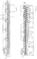
- the fibrous web 1 passes through for dewatering together with a press felt formed by two press rolls press nip 9. Subsequently enters the fibrous web 1 in the dryer section, in which the fibrous web 1 is heated by the direct contact with heated drying cylinders 2 and dried.
- the drying sections consist of several drying groups, each drying group being formed by one or two rows of drying cylinders 2 arranged one above the other.
- each drying cylinder 3 is assigned to each row of drying cylinders 2 for supporting the fibrous web 1.
- Drying takes place on one side at least in the first part of the dryer section, since only the lower side of the fibrous web 1 comes into contact with the drying cylinders 2 arranged in a row here. Between the drying cylinders 2, the fibrous web 1, together with the corresponding drying wire 3, wraps around an evacuated guide roll 4, wherein the drying wire 3 lies between the guide roll 4 and the fibrous web 1.
- the evacuated guide rolls 4 have a perforated roll shell whose interior is connected to a vacuum source.
- the negative pressure ensures that the fibrous web 1 is sucked during the wrapping of the guide roller 4 for drying wire 3 out.
- moistening 5.6 located in the dryer section two moistening 5.6 in the form of transverse to the web direction 10 nozzle moisteners having a plurality of transversely to the web running direction 10 juxtaposed pneumatic atomizer nozzles.
- These moistening devices 5, 6 are arranged opposite to the fibrous web 1 and with respect to the amount of liquid applied to the fibrous web 1 in zones transversely to the web running direction 10 separately controllable.
- the adjustment of the degree of emanating from the zones humidification is carried out in dependence on the measured moisture profile of the fibrous web 1 in the form of a scheme.
- a second moistening device 6 is assigned to the last evacuated guide roller 4. This has only one zone here.
- the dry content of the fibrous web is more than 80%.
- Each of the first 4 drying groups consists of a row of drying cylinders 2 and the last two are each made up of two rows arranged one above the other.
- a first moistening device 5 in the web running direction 10 is possible in the looped area of an evacuated guide roll 4, since there is a sufficiently large dry content of more than 60%.
- this moistening device 5 serves to correct the moisture transverse profile of the fibrous web 1.
- a second moistening device 6 can be attached to a suctioned guide roller 4.
- the dry content of the fibrous web 1 is more than 80%.
- This moistening device 6 is used to correct the moisture cross profile and to influence the curl of the fibrous web 1 and therefore has more zones than the first moistening device 5.
Landscapes
- Paper (AREA)
- Treatment Of Fiber Materials (AREA)
- Drying Of Solid Materials (AREA)
Claims (21)
- Partie de séchage pour le séchage d'une bande de papier, de carton, d'essuie-tout ou d'une autre matière fibreuse (1) dans une machine de fabrication et/ou de traitement de la bande de matière fibreuse (1), dans laquelle la partie de séchage se compose de plusieurs groupes de séchage, dans lesquels la bande de matière fibreuse (1) supportée par une toile de séchage (3) est respectivement guidée sur plusieurs cylindres de séchage chauffés (2), dans laquelle plusieurs de préférence deux dispositifs d'humidification (5, 6) sont disposés à l'intérieur de la partie de séchage à différentes positions par rapport à la bande de matière fibreuse (1), dans laquelle au moins un, de préférence tous les dispositif(s) d'humidification (5, 6) possède(nt) plusieurs buses disposées l'une à côté de l'autre transversalement à la direction de défilement (10) de la bande, dans laquelle, au moins dans un dispositif d'humidification (5, 6), la quantité de liquide apportée sur la bande de matière fibreuse (1) est réglable séparément dans des zones transversalement à la direction de défilement (10) de la bande, caractérisée en ce que la bande de matière fibreuse (1) est guidée sur des cylindres de déviation aspirants (4) entre les cylindres de séchage (2) d'un groupe de séchage de la partie de séchage, dans laquelle la toile de séchage (3) est située entre le cylindre de déviation (4) et la bande de matière fibreuse (1), en ce qu'au moins un, de préférence tous les dispositif(s) d'humidification (5, 6) est/sont disposé(s) dans la région d'un cylindre de déviation aspirant (4) et en ce que les dispositifs d'humidification (5, 6) possèdent un nombre différent de zones.
- Partie de séchage selon la revendication 1, caractérisée en ce que les buses sont constituées au moins en partie par des buses de pulvérisation pneumatiques.
- Partie de séchage selon l'une quelconque des revendications précédentes, caractérisée en ce que les dispositifs d'humidification (5, 6) apportent des quantités de liquide différentes sur la bande de matière fibreuse (1).
- Partie de séchage selon l'une quelconque des revendications précédentes, caractérisée en ce que les dispositifs d'humidification (5, 6) délivrent le liquide chaque fois avec des diamètres de gouttelettes moyens différents, dans laquelle le diamètre de gouttelette moyen selon Sauter ne dépasse pas une limite supérieure de préférence de 100 %m.
- Partie de séchage selon l'une quelconque des revendications précédentes, caractérisée en ce que les dispositifs d'humidification (5, 6) comprennent différents types de buse et/ou différents angles de pulvérisation par rapport à la bande de matière fibreuse (1).
- Partie de séchage selon l'une quelconque des revendications précédentes, caractérisée en ce que les zones des dispositifs d'humidification (5, 6) sont de largeur différente.
- Partie de séchage selon l'une quelconque des revendications 1 à 6, caractérisée en ce que le dispositif d'humidification (5, 6) avec un petit nombre de zones possède de 1 à 25 zones.
- Partie de séchage selon l'une quelconque des revendications 1 à 7, caractérisée en ce que le dispositif d'humidification (5, 6) avec un grand nombre de zones comporte des zones d'une largeur comprise entre 20 et 150 mm, de préférence entre 20 et 50 mm.
- Partie de séchage selon l'une quelconque des revendications précédentes, caractérisée en ce que le premier dispositif d'humidification (5) dans la direction de défilement (10) de la bande est disposé dans une région de la partie de séchage, dans laquelle la siccité de la bande de matière fibreuse (1) vaut au moins 60 %, mais est située au moins 2 % en dessous de la siccité que la bande de matière fibreuse (1) présente à la fin de la partie de séchage.
- Partie de séchage selon l'une quelconque des revendications précédentes, caractérisée en ce que le dernier dispositif d'humidification (6) dans la direction de défilement (10) de la bande est disposé dans une région de la partie de séchage, dans laquelle la siccité de la bande de matière fibreuse (1) vaut au moins 80 %.
- Partie de séchage selon l'une quelconque des revendications précédentes, caractérisée en ce que les dispositifs d'humidification (5, 6) sont utilisés dans des groupes de séchage de la partie de séchage, dans lesquels seul un côté de la bande de matière fibreuse (1) vient en contact avec les cylindres de séchage (2).
- Partie de séchage selon l'une quelconque des revendications 1 à 11, caractérisée en ce que le dernier dispositif d'humidification (6) dans la direction de défilement (10) de la bande est disposé dans la région du dernier cylindre de déviation aspirant (4) de la partie de séchage.
- Partie de séchage selon l'une quelconque des revendications 1 à 12, caractérisée en ce que le premier dispositif d'humidification (5) dans la direction de défilement (10) de la bande est disposé dans la région du dernier cylindre de déviation aspirant (4) de l'avant-dernier groupe de séchage de la partie de séchage.
- Partie de séchage selon l'une quelconque des revendications précédentes, caractérisée en ce que le premier dispositif d'humidification (5) dans la direction de défilement (10) de la bande est utilisé essentiellement, de préférence exclusivement pour la correction du profil d'humidité transversal de la bande de matière fibreuse (1) et est réglé en conséquence.
- Partie de séchage selon l'une quelconque des revendications précédentes, caractérisée en ce que le dernier dispositif d'humidification (6) dans la direction de défilement (10) de la bande est utilisé essentiellement, de préférence exclusivement pour la correction de la tendance à l'enroulement de la bande de matière fibreuse (1) et est réglé en conséquence.
- Partie de séchage selon l'une quelconque des revendications précédentes, caractérisée en ce que le premier dispositif d'humidification (5) dans la direction de défilement (10) de la bande possède plus de zones que le dernier dispositif d'humidification (6).
- Partie de séchage selon l'une quelconque des revendications 1 à 14, caractérisée en ce que le dernier dispositif d'humidification (6) dans la direction de défilement (10) de la bande est utilisé pour la correction du profil d'humidité transversal et de la tendance à l'enroulement de la bande de matière fibreuse (1) et est réglé en conséquence.
- Partie de séchage selon la revendication 17, caractérisée en ce que le dernier dispositif d'humidification (6) dans la direction de défilement (10) de la bande présente plus de zones que le premier dispositif d'humidification (5).
- Partie de séchage selon l'une quelconque des revendications précédentes, caractérisée en ce que seul un côté de la bande de matière fibreuse (1) vient chaque fois en contact avec les cylindres de séchage (2) dans tous les groupes de séchage de la partie de séchage.
- Partie de séchage selon l'une quelconque des revendications 1 à 18, caractérisée en ce que de préférence dans le ou les deux dernier(s) groupe(s) de refroidissement de la partie de séchage, les deux côtés et avant cela seul chaque fois un côté de la bande de matière fibreuse (1) viennent/vient en contact avec les cylindres de séchage (2).
- Utilisation de la partie de séchage selon l'une quelconque des revendications précédentes pour des bandes de matière fibreuse (1) à plusieurs couches ou pour des bandes de matière fibreuse (1) qui sont traitées sur un côté avec des substances influençant les propriétés de surface.
Applications Claiming Priority (3)
| Application Number | Priority Date | Filing Date | Title |
|---|---|---|---|
| DE10233795A DE10233795A1 (de) | 2002-07-25 | 2002-07-25 | Trockenpartie |
| DE10233795 | 2002-07-25 | ||
| PCT/EP2003/050291 WO2004011722A1 (fr) | 2002-07-25 | 2003-07-08 | Train de sechage |
Publications (2)
| Publication Number | Publication Date |
|---|---|
| EP1527232A1 EP1527232A1 (fr) | 2005-05-04 |
| EP1527232B1 true EP1527232B1 (fr) | 2017-03-22 |
Family
ID=30128360
Family Applications (1)
| Application Number | Title | Priority Date | Filing Date |
|---|---|---|---|
| EP03771111.6A Expired - Lifetime EP1527232B1 (fr) | 2002-07-25 | 2003-07-08 | Partie de séchage |
Country Status (7)
| Country | Link |
|---|---|
| US (1) | US7459062B2 (fr) |
| EP (1) | EP1527232B1 (fr) |
| JP (1) | JP4528618B2 (fr) |
| CN (1) | CN100352999C (fr) |
| AU (1) | AU2003254501A1 (fr) |
| DE (1) | DE10233795A1 (fr) |
| WO (1) | WO2004011722A1 (fr) |
Families Citing this family (6)
| Publication number | Priority date | Publication date | Assignee | Title |
|---|---|---|---|---|
| DE102004017809A1 (de) * | 2004-04-13 | 2005-10-27 | Voith Paper Patent Gmbh | Trockenanordnung |
| DE102008000288A1 (de) | 2008-02-13 | 2009-08-20 | Voith Patent Gmbh | Verfahren und Vorrichtung zur Steuerung und/oder Regelung der Feuchte einer Materialbahn und Maschine zur Herstellung einer Materialbahn mit einer derartigen Vorrichtung |
| US9481777B2 (en) | 2012-03-30 | 2016-11-01 | The Procter & Gamble Company | Method of dewatering in a continuous high internal phase emulsion foam forming process |
| US9670616B2 (en) | 2014-12-11 | 2017-06-06 | Georgia-Pacific Consumer Products Lp | Active web spreading and stabilization shower |
| DE102020102731A1 (de) * | 2020-02-04 | 2021-08-05 | Voith Patent Gmbh | Verfahren zur Herstellung einer Deckenpapierbahn |
| DE102021103519A1 (de) * | 2021-02-15 | 2022-08-18 | Koehler Innovation & Technology Gmbh | Verfahren zur Herstellung einer Faserstoffbahn |
Family Cites Families (19)
| Publication number | Priority date | Publication date | Assignee | Title |
|---|---|---|---|---|
| SE429771B (sv) * | 1978-09-25 | 1983-09-26 | Nordiskafilt Ab | Sett att reglera fuktprofilen hos en fiberbana |
| FI72552C (fi) * | 1984-02-08 | 1987-06-08 | Waertsilae Oy Ab | Foerfarande och anordning foer behandling av bana. |
| US5065673A (en) * | 1989-09-19 | 1991-11-19 | Measurex Corporation | Cross-directional moisture control system and method |
| FI91900C (fi) * | 1990-12-17 | 1994-08-25 | Valmet Paper Machinery Inc | Menetelmä paperikoneen kuivatusosalla paperin käyristymistaipumuksen vähentämiseksi ja menetelmän toteuttamiseen tarkoitettu kuivatusosa |
| FI103820B1 (fi) | 1993-11-30 | 1999-09-30 | Valmet Paper Machinery Inc | Menetelmät paperirainan kuivatuksessa sekä paperikoneen kuivatusosat |
| US5632101A (en) * | 1994-09-16 | 1997-05-27 | Voith Sulzer Papiermaschinen Gmbh | All top-felted single-tier drying section with post drying section curl control |
| DE9414963U1 (de) * | 1994-09-16 | 1994-11-03 | J.M. Voith Gmbh, 89522 Heidenheim | Trockenpartie |
| US5771603A (en) * | 1994-09-16 | 1998-06-30 | Voith Sulzer Papiermashinen Gmbh | Dryer section |
| US5592751A (en) * | 1994-11-23 | 1997-01-14 | Voith Sulzer Papiermaschinen Gmbh | Dryer section having combination of single and double tier dryer groups |
| DE19627669C2 (de) * | 1996-07-10 | 2001-03-01 | Stora Enso Publication Paper A | Verfahren zur Verbesserung von Druckpapieren |
| US6001421A (en) * | 1996-12-03 | 1999-12-14 | Valmet Corporation | Method for drying paper and a dry end of a paper machine |
| FI981594L (fi) | 1998-07-10 | 2000-01-11 | Valmet Corp | Menetelmä ja laitteisto rainan kostutuksessa |
| ES2217781T3 (es) | 1998-07-10 | 2004-11-01 | Metso Paper, Inc. | Metodo de fabricacion de papel calandrado. |
| EP1097269B1 (fr) | 1998-07-10 | 2004-03-24 | Metso Paper, Inc. | Procede et appareil servant a fabriquer un papier pour impression traite en surface |
| DE19901400A1 (de) * | 1999-01-15 | 2000-07-20 | Voith Sulzer Papiertech Patent | Trocknungs- und Glättungseinheit für Faserstoffbahnen |
| DE19921592A1 (de) | 1999-05-07 | 2000-11-09 | Voith Sulzer Papiertech Patent | Applikationsvorrichtung und -verfahren für eine Papiermaschine |
| DE10052187B4 (de) | 2000-10-20 | 2013-12-24 | Voith Patent Gmbh | Verfahren zum Glätten einer Materialbahn sowie Kalander zur Durchführung des Verfahrens |
| FI109213B (fi) * | 2000-11-24 | 2002-06-14 | Metso Paper Inc | Menetelmä ja laite paperirainan kosteus- tai päällystemääräprofiilin hallitsemiseksi |
| US6699365B2 (en) * | 2001-10-22 | 2004-03-02 | Abb Inc. | Method of wetting webs of paper or other hygroscopic material |
-
2002
- 2002-07-25 DE DE10233795A patent/DE10233795A1/de not_active Withdrawn
-
2003
- 2003-07-08 CN CNB038178869A patent/CN100352999C/zh not_active Expired - Lifetime
- 2003-07-08 JP JP2004523808A patent/JP4528618B2/ja not_active Expired - Fee Related
- 2003-07-08 AU AU2003254501A patent/AU2003254501A1/en not_active Abandoned
- 2003-07-08 EP EP03771111.6A patent/EP1527232B1/fr not_active Expired - Lifetime
- 2003-07-08 WO PCT/EP2003/050291 patent/WO2004011722A1/fr not_active Ceased
-
2005
- 2005-01-24 US US11/040,032 patent/US7459062B2/en not_active Expired - Fee Related
Non-Patent Citations (1)
| Title |
|---|
| None * |
Also Published As
| Publication number | Publication date |
|---|---|
| US7459062B2 (en) | 2008-12-02 |
| AU2003254501A1 (en) | 2004-02-16 |
| JP2005533938A (ja) | 2005-11-10 |
| WO2004011722A1 (fr) | 2004-02-05 |
| CN100352999C (zh) | 2007-12-05 |
| US20050138837A1 (en) | 2005-06-30 |
| EP1527232A1 (fr) | 2005-05-04 |
| JP4528618B2 (ja) | 2010-08-18 |
| DE10233795A1 (de) | 2004-02-12 |
| CN1671922A (zh) | 2005-09-21 |
Similar Documents
| Publication | Publication Date | Title |
|---|---|---|
| EP1770209B1 (fr) | Procédé et dispositif pour la production d'une bande de papier tissu | |
| EP1072721B1 (fr) | Machine à papier | |
| EP1020559B1 (fr) | Dispositif pour secher et lisser des bandes fibreuses | |
| DE29815847U1 (de) | Vorrichtung zur Online-Herstellung von Papier | |
| EP1225270B1 (fr) | Procédé pour le conditionnement d' une bande en mouvement | |
| EP1697584A1 (fr) | Machine a papier | |
| AT507747B1 (de) | Verfahren und vorrichtung zum beschichten einer bahn eines fasermaterials mit wenigstens zwei schichten einer beschichtung | |
| DE10116840A1 (de) | Verfahren und Vorrichtung zum Glätten einer Materialbahn | |
| WO2004011722A1 (fr) | Train de sechage | |
| DE102004017810A1 (de) | Trockenanordnung | |
| EP1540078B1 (fr) | Dispositif et procede de production et/ou traitement d'une bande de matiere fibreuse | |
| DE10052187B4 (de) | Verfahren zum Glätten einer Materialbahn sowie Kalander zur Durchführung des Verfahrens | |
| EP3601666B1 (fr) | Traitement de bande | |
| EP1746203B1 (fr) | Section de séchage | |
| DE102006011853A1 (de) | Verfahren und Vorrichtung zum Befeuchten einer Faserstoffbahn | |
| DE10025240A1 (de) | Verfahren und Vorrichtung zur Feuchtequerprofil-Korrektur | |
| EP1702106A1 (fr) | Machine papier | |
| DE10056138A1 (de) | Pressenpartie | |
| DE102006051537A1 (de) | Vorrichtung zum Bearbeiten einer Bahn aus Papier oder Karton | |
| WO2023025463A1 (fr) | Machine de production et/ou de traitement d'une bande de fibres | |
| EP1305472A1 (fr) | Bande sans fin | |
| DE102021121837A1 (de) | Maschine zur Herstellung und/oder Behandlung einer Faserstoffbahn | |
| EP1826317A1 (fr) | Machine pour fabriquer une bande fibreuse | |
| DE102004043375A1 (de) | Bahnbefeuchtung | |
| DE102006059544A1 (de) | Verfahren und Vorrichtung zur Beschichtung und Glättung |
Legal Events
| Date | Code | Title | Description |
|---|---|---|---|
| PUAI | Public reference made under article 153(3) epc to a published international application that has entered the european phase |
Free format text: ORIGINAL CODE: 0009012 |
|
| 17P | Request for examination filed |
Effective date: 20050225 |
|
| AK | Designated contracting states |
Kind code of ref document: A1 Designated state(s): AT BE BG CH CY CZ DE DK EE ES FI FR GB GR HU IE IT LI LU MC NL PT RO SE SI SK TR |
|
| AX | Request for extension of the european patent |
Extension state: AL LT LV MK |
|
| DAX | Request for extension of the european patent (deleted) | ||
| RAP1 | Party data changed (applicant data changed or rights of an application transferred) |
Owner name: VOITH PATENT GMBH |
|
| RIN1 | Information on inventor provided before grant (corrected) |
Inventor name: WEGEHAUPT, FRANK Inventor name: MAYER, ROLAND Inventor name: OECHSLE, MARKUS Inventor name: STEIN, ANTJE |
|
| 17Q | First examination report despatched |
Effective date: 20110513 |
|
| REG | Reference to a national code |
Ref country code: DE Ref legal event code: R079 Ref document number: 50315636 Country of ref document: DE Free format text: PREVIOUS MAIN CLASS: D21F0007000000 Ipc: D21F0005040000 |
|
| GRAP | Despatch of communication of intention to grant a patent |
Free format text: ORIGINAL CODE: EPIDOSNIGR1 |
|
| INTG | Intention to grant announced |
Effective date: 20161020 |
|
| RIC1 | Information provided on ipc code assigned before grant |
Ipc: D21G 7/00 20060101ALI20161007BHEP Ipc: D21F 5/04 20060101AFI20161007BHEP |
|
| GRAS | Grant fee paid |
Free format text: ORIGINAL CODE: EPIDOSNIGR3 |
|
| GRAA | (expected) grant |
Free format text: ORIGINAL CODE: 0009210 |
|
| RIN1 | Information on inventor provided before grant (corrected) |
Inventor name: WEGEHAUPT, FRANK Inventor name: STEIN, ANTJE Inventor name: OECHSLE, MARKUS Inventor name: MAYER, ROLAND |
|
| AK | Designated contracting states |
Kind code of ref document: B1 Designated state(s): AT BE BG CH CY CZ DE DK EE ES FI FR GB GR HU IE IT LI LU MC NL PT RO SE SI SK TR |
|
| REG | Reference to a national code |
Ref country code: DE Ref legal event code: R081 Ref document number: 50315636 Country of ref document: DE Owner name: VOITH PATENT GMBH, DE Free format text: FORMER OWNER: VOITH PAPER PATENT GMBH, 89522 HEIDENHEIM, DE Ref country code: GB Ref legal event code: FG4D Free format text: NOT ENGLISH |
|
| REG | Reference to a national code |
Ref country code: CH Ref legal event code: EP |
|
| REG | Reference to a national code |
Ref country code: AT Ref legal event code: REF Ref document number: 877913 Country of ref document: AT Kind code of ref document: T Effective date: 20170415 |
|
| REG | Reference to a national code |
Ref country code: IE Ref legal event code: FG4D Free format text: LANGUAGE OF EP DOCUMENT: GERMAN |
|
| REG | Reference to a national code |
Ref country code: DE Ref legal event code: R096 Ref document number: 50315636 Country of ref document: DE |
|
| REG | Reference to a national code |
Ref country code: NL Ref legal event code: MP Effective date: 20170322 |
|
| PG25 | Lapsed in a contracting state [announced via postgrant information from national office to epo] |
Ref country code: GR Free format text: LAPSE BECAUSE OF FAILURE TO SUBMIT A TRANSLATION OF THE DESCRIPTION OR TO PAY THE FEE WITHIN THE PRESCRIBED TIME-LIMIT Effective date: 20170623 |
|
| PG25 | Lapsed in a contracting state [announced via postgrant information from national office to epo] |
Ref country code: BG Free format text: LAPSE BECAUSE OF FAILURE TO SUBMIT A TRANSLATION OF THE DESCRIPTION OR TO PAY THE FEE WITHIN THE PRESCRIBED TIME-LIMIT Effective date: 20170622 Ref country code: SE Free format text: LAPSE BECAUSE OF FAILURE TO SUBMIT A TRANSLATION OF THE DESCRIPTION OR TO PAY THE FEE WITHIN THE PRESCRIBED TIME-LIMIT Effective date: 20170322 |
|
| PG25 | Lapsed in a contracting state [announced via postgrant information from national office to epo] |
Ref country code: NL Free format text: LAPSE BECAUSE OF FAILURE TO SUBMIT A TRANSLATION OF THE DESCRIPTION OR TO PAY THE FEE WITHIN THE PRESCRIBED TIME-LIMIT Effective date: 20170322 |
|
| PG25 | Lapsed in a contracting state [announced via postgrant information from national office to epo] |
Ref country code: ES Free format text: LAPSE BECAUSE OF FAILURE TO SUBMIT A TRANSLATION OF THE DESCRIPTION OR TO PAY THE FEE WITHIN THE PRESCRIBED TIME-LIMIT Effective date: 20170322 Ref country code: EE Free format text: LAPSE BECAUSE OF FAILURE TO SUBMIT A TRANSLATION OF THE DESCRIPTION OR TO PAY THE FEE WITHIN THE PRESCRIBED TIME-LIMIT Effective date: 20170322 Ref country code: RO Free format text: LAPSE BECAUSE OF FAILURE TO SUBMIT A TRANSLATION OF THE DESCRIPTION OR TO PAY THE FEE WITHIN THE PRESCRIBED TIME-LIMIT Effective date: 20170322 Ref country code: CZ Free format text: LAPSE BECAUSE OF FAILURE TO SUBMIT A TRANSLATION OF THE DESCRIPTION OR TO PAY THE FEE WITHIN THE PRESCRIBED TIME-LIMIT Effective date: 20170322 Ref country code: SK Free format text: LAPSE BECAUSE OF FAILURE TO SUBMIT A TRANSLATION OF THE DESCRIPTION OR TO PAY THE FEE WITHIN THE PRESCRIBED TIME-LIMIT Effective date: 20170322 Ref country code: IT Free format text: LAPSE BECAUSE OF FAILURE TO SUBMIT A TRANSLATION OF THE DESCRIPTION OR TO PAY THE FEE WITHIN THE PRESCRIBED TIME-LIMIT Effective date: 20170322 |
|
| PG25 | Lapsed in a contracting state [announced via postgrant information from national office to epo] |
Ref country code: PT Free format text: LAPSE BECAUSE OF FAILURE TO SUBMIT A TRANSLATION OF THE DESCRIPTION OR TO PAY THE FEE WITHIN THE PRESCRIBED TIME-LIMIT Effective date: 20170724 |
|
| REG | Reference to a national code |
Ref country code: DE Ref legal event code: R097 Ref document number: 50315636 Country of ref document: DE |
|
| PLBE | No opposition filed within time limit |
Free format text: ORIGINAL CODE: 0009261 |
|
| STAA | Information on the status of an ep patent application or granted ep patent |
Free format text: STATUS: NO OPPOSITION FILED WITHIN TIME LIMIT |
|
| PG25 | Lapsed in a contracting state [announced via postgrant information from national office to epo] |
Ref country code: DK Free format text: LAPSE BECAUSE OF FAILURE TO SUBMIT A TRANSLATION OF THE DESCRIPTION OR TO PAY THE FEE WITHIN THE PRESCRIBED TIME-LIMIT Effective date: 20170322 |
|
| 26N | No opposition filed |
Effective date: 20180102 |
|
| PG25 | Lapsed in a contracting state [announced via postgrant information from national office to epo] |
Ref country code: SI Free format text: LAPSE BECAUSE OF FAILURE TO SUBMIT A TRANSLATION OF THE DESCRIPTION OR TO PAY THE FEE WITHIN THE PRESCRIBED TIME-LIMIT Effective date: 20170322 |
|
| REG | Reference to a national code |
Ref country code: CH Ref legal event code: PL |
|
| GBPC | Gb: european patent ceased through non-payment of renewal fee |
Effective date: 20170708 |
|
| REG | Reference to a national code |
Ref country code: IE Ref legal event code: MM4A |
|
| REG | Reference to a national code |
Ref country code: FR Ref legal event code: ST Effective date: 20180330 |
|
| PG25 | Lapsed in a contracting state [announced via postgrant information from national office to epo] |
Ref country code: GB Free format text: LAPSE BECAUSE OF NON-PAYMENT OF DUE FEES Effective date: 20170708 Ref country code: IE Free format text: LAPSE BECAUSE OF NON-PAYMENT OF DUE FEES Effective date: 20170708 Ref country code: CH Free format text: LAPSE BECAUSE OF NON-PAYMENT OF DUE FEES Effective date: 20170731 Ref country code: LI Free format text: LAPSE BECAUSE OF NON-PAYMENT OF DUE FEES Effective date: 20170731 |
|
| PG25 | Lapsed in a contracting state [announced via postgrant information from national office to epo] |
Ref country code: FR Free format text: LAPSE BECAUSE OF NON-PAYMENT OF DUE FEES Effective date: 20170731 |
|
| REG | Reference to a national code |
Ref country code: BE Ref legal event code: MM Effective date: 20170731 |
|
| PG25 | Lapsed in a contracting state [announced via postgrant information from national office to epo] |
Ref country code: LU Free format text: LAPSE BECAUSE OF NON-PAYMENT OF DUE FEES Effective date: 20170708 |
|
| PG25 | Lapsed in a contracting state [announced via postgrant information from national office to epo] |
Ref country code: BE Free format text: LAPSE BECAUSE OF NON-PAYMENT OF DUE FEES Effective date: 20170731 |
|
| PG25 | Lapsed in a contracting state [announced via postgrant information from national office to epo] |
Ref country code: HU Free format text: LAPSE BECAUSE OF FAILURE TO SUBMIT A TRANSLATION OF THE DESCRIPTION OR TO PAY THE FEE WITHIN THE PRESCRIBED TIME-LIMIT; INVALID AB INITIO Effective date: 20030708 Ref country code: MC Free format text: LAPSE BECAUSE OF FAILURE TO SUBMIT A TRANSLATION OF THE DESCRIPTION OR TO PAY THE FEE WITHIN THE PRESCRIBED TIME-LIMIT Effective date: 20170322 |
|
| PG25 | Lapsed in a contracting state [announced via postgrant information from national office to epo] |
Ref country code: CY Free format text: LAPSE BECAUSE OF NON-PAYMENT OF DUE FEES Effective date: 20170322 |
|
| PG25 | Lapsed in a contracting state [announced via postgrant information from national office to epo] |
Ref country code: TR Free format text: LAPSE BECAUSE OF FAILURE TO SUBMIT A TRANSLATION OF THE DESCRIPTION OR TO PAY THE FEE WITHIN THE PRESCRIBED TIME-LIMIT Effective date: 20170322 |
|
| PGFP | Annual fee paid to national office [announced via postgrant information from national office to epo] |
Ref country code: FI Payment date: 20220721 Year of fee payment: 20 Ref country code: DE Payment date: 20220620 Year of fee payment: 20 Ref country code: AT Payment date: 20220721 Year of fee payment: 20 |
|
| REG | Reference to a national code |
Ref country code: DE Ref legal event code: R071 Ref document number: 50315636 Country of ref document: DE |
|
| REG | Reference to a national code |
Ref country code: AT Ref legal event code: MK07 Ref document number: 877913 Country of ref document: AT Kind code of ref document: T Effective date: 20230708 |